US9503213B2 - Systems and methods for data rate optimization in a WCAN system with injection-locked clocking - Google Patents
Systems and methods for data rate optimization in a WCAN system with injection-locked clocking Download PDFInfo
- Publication number
- US9503213B2 US9503213B2 US13/997,499 US201213997499A US9503213B2 US 9503213 B2 US9503213 B2 US 9503213B2 US 201213997499 A US201213997499 A US 201213997499A US 9503213 B2 US9503213 B2 US 9503213B2
- Authority
- US
- United States
- Prior art keywords
- prp
- ber
- error rate
- bit error
- ilt
- Prior art date
- Legal status (The legal status is an assumption and is not a legal conclusion. Google has not performed a legal analysis and makes no representation as to the accuracy of the status listed.)
- Active
Links
Images


Classifications
-
- H—ELECTRICITY
- H04—ELECTRIC COMMUNICATION TECHNIQUE
- H04L—TRANSMISSION OF DIGITAL INFORMATION, e.g. TELEGRAPHIC COMMUNICATION
- H04L1/00—Arrangements for detecting or preventing errors in the information received
- H04L1/0001—Systems modifying transmission characteristics according to link quality, e.g. power backoff
- H04L1/0002—Systems modifying transmission characteristics according to link quality, e.g. power backoff by adapting the transmission rate
-
- G—PHYSICS
- G06—COMPUTING; CALCULATING OR COUNTING
- G06F—ELECTRIC DIGITAL DATA PROCESSING
- G06F1/00—Details not covered by groups G06F3/00 - G06F13/00 and G06F21/00
-
- H—ELECTRICITY
- H03—ELECTRONIC CIRCUITRY
- H03L—AUTOMATIC CONTROL, STARTING, SYNCHRONISATION, OR STABILISATION OF GENERATORS OF ELECTRONIC OSCILLATIONS OR PULSES
- H03L7/00—Automatic control of frequency or phase; Synchronisation
-
- H—ELECTRICITY
- H04—ELECTRIC COMMUNICATION TECHNIQUE
- H04B—TRANSMISSION
- H04B17/00—Monitoring; Testing
-
- H—ELECTRICITY
- H04—ELECTRIC COMMUNICATION TECHNIQUE
- H04B—TRANSMISSION
- H04B17/00—Monitoring; Testing
- H04B17/20—Monitoring; Testing of receivers
- H04B17/21—Monitoring; Testing of receivers for calibration; for correcting measurements
-
- H—ELECTRICITY
- H04—ELECTRIC COMMUNICATION TECHNIQUE
- H04J—MULTIPLEX COMMUNICATION
- H04J3/00—Time-division multiplex systems
-
- H—ELECTRICITY
- H04—ELECTRIC COMMUNICATION TECHNIQUE
- H04L—TRANSMISSION OF DIGITAL INFORMATION, e.g. TELEGRAPHIC COMMUNICATION
- H04L1/00—Arrangements for detecting or preventing errors in the information received
-
- H—ELECTRICITY
- H04—ELECTRIC COMMUNICATION TECHNIQUE
- H04L—TRANSMISSION OF DIGITAL INFORMATION, e.g. TELEGRAPHIC COMMUNICATION
- H04L7/00—Arrangements for synchronising receiver with transmitter
- H04L7/02—Speed or phase control by the received code signals, the signals containing no special synchronisation information
- H04L7/027—Speed or phase control by the received code signals, the signals containing no special synchronisation information extracting the synchronising or clock signal from the received signal spectrum, e.g. by using a resonant or bandpass circuit
- H04L7/0276—Self-sustaining, e.g. by tuned delay line and a feedback path to a logical gate
-
- H—ELECTRICITY
- H04—ELECTRIC COMMUNICATION TECHNIQUE
- H04W—WIRELESS COMMUNICATION NETWORKS
- H04W28/00—Network traffic management; Network resource management
- H04W28/02—Traffic management, e.g. flow control or congestion control
- H04W28/06—Optimizing the usage of the radio link, e.g. header compression, information sizing, discarding information
-
- H—ELECTRICITY
- H04—ELECTRIC COMMUNICATION TECHNIQUE
- H04W—WIRELESS COMMUNICATION NETWORKS
- H04W56/00—Synchronisation arrangements
-
- H—ELECTRICITY
- H04—ELECTRIC COMMUNICATION TECHNIQUE
- H04W—WIRELESS COMMUNICATION NETWORKS
- H04W56/00—Synchronisation arrangements
- H04W56/001—Synchronization between nodes
-
- H—ELECTRICITY
- H04—ELECTRIC COMMUNICATION TECHNIQUE
- H04L—TRANSMISSION OF DIGITAL INFORMATION, e.g. TELEGRAPHIC COMMUNICATION
- H04L1/00—Arrangements for detecting or preventing errors in the information received
- H04L1/20—Arrangements for detecting or preventing errors in the information received using signal quality detector
- H04L1/203—Details of error rate determination, e.g. BER, FER or WER
Definitions
- WCAN or wireless chip area networks may provide for the communication of various chips within a system without direct wiring.
- Wireless inter-chip communication systems using pulse injection-locking for receiver phase synchronization achieve a data rate of 500 Mbps (megabits per second), but exhibit severe multipath interference within a device chassis thereby severely degrading the receiver bit error rate BER at high data-rates due to the inter-symbol interference.
- FIGS. 1 a and 1 b show one embodiment of transmitter and receiver for use with an injection-locked pulse repetition period (ILPRP) optimized system;
- IPRP injection-locked pulse repetition period
- FIG. 2 shows an example of channel response within a computer chassis
- FIG. 3 shows an example of a bath-tub curve of bit error rate (BER) vs. possible phase positions
- FIG. 4 show a method of optimizing the pulse repetition period (PRP) in an ILPRP system
- FIG. 5 shows an example of measured receiver BER versus PRP
- FIG. 6 shows a conceptual drawing representative of channel response within a computer chassis
- FIG. 7 shows one embodiment of a system including multiple injection-locked pulse repetition period (ILPRP) optimized system.
- IPRP injection-locked pulse repetition period
- ILPRPO injection-locked pulse repetition period optimized system
- the Proposed method gives about 20% data rate gain compared with typical solutions.
- the ILPRPO system is primarily utilized on chips with WCAN transceivers using injection-locked clocking technique. In alternatives, it can be implemented into any system where the channel response is expected to be static. Systems with a static channel response are typically those where objects that cause interference with the transmission path are stationary.
- FIGS. 1 a and 1 b show one embodiment of a transceiver for use with an ILPRPO system.
- this system may be referred to as an ILT system (an injection-locked transmission system).
- the considered transceiver shown in FIGS. 1 a and 1 b includes a pulse-injection-locking receiver.
- the provision of a pulse-injection-locking receiver provides for an energy-efficient scheme of synchronization of the local oscillator with the received signal carrier and clock synchronization of the receiver with the transmitter. This is at least in part because oversampling of the signal is not necessary to avoid phase shifts of transmission signal and sampling.
- Transmitter 110 includes a data source 115 providing the data to be wirelessly transmitted.
- the transmitter 110 further includes a pseudo-random binary sequence transmitter 120 , a non-return to zero to return to zero data converter 125 , a variable pulse window 130 , an injection locked voltage control oscillator 135 , a frequency divider 140 , a combiner 145 , and an antenna 150 .
- the receiver 120 includes a receiver antenna 155 , a receiver pulse injection locking system 157 , including a low noise amplifier 160 , a variable amplifier 161 , and an injection locked voltage control oscillator 135 , a phase shifter 165 , a divider 140 and a five level flash analog to digital converter 170 .
- the result of reception, data 175 is returned to a microprocessor.
- Received pulse is amplified by a two-stage low-noise amplifier (LNA) 160 before being directly injected into both a five-level flash ADC (analog to digital converter) 170 and a 3.4 4.5 GHz, injection-locked VCO (IL-VCO or voltage controlled oscillator) On-off keying (OOK) modulation scheme is chosen due to its simplicity.
- LNA low-noise amplifier
- IL-VCO injection-locked VCO
- OLK On-off keying
- FIG. 2 shows channel response within a computer chassis.
- the y-axis 210 shows the amplitude of the signal.
- the x-axis 220 shows the time in nanoseconds of the PRP or pulse repetition period.
- pulse repetition period is usually chosen greater than channel response duration. This leads to a significant loss in data rate. For example, the rate drops from 500 Mbps to 125 Mbps (megabits per second) for the typical channel response within an example of a computer chassis given in FIG. 2 .
- FIG. 3 shows a bath-tub curve of bit error rate (BER) vs. possible phase positions.
- the y-axis 310 denotes the BER on a logarithmic scale.
- the x-axis 320 shows possible phase positions for the transmission.
- Line 330 denotes 500 Mbps
- line 340 denotes 153 Mbps (the optimal rate in this example)
- line 350 denotes 125 Mbps (the conservative default transmission rate that would be chosen in absence of analysis.
- the optimal phase position of the ADC (analog to digital) sampling clock can be set at startup by measuring the BER by building a bath-tub curve, sweeping through all possible phase positions (see FIG. 3 line 350 ).
- BER is chosen to fit the parameters of the transmission system.
- WCAN systems Due to the static nature of the environment that in which WCAN systems operate, i.e., those producing a static channel response, they may be configured to measure the channel response beforehand. Knowledge of the main reflectors locations can be used to assist in determining the channel response beforehand. In many configurations, it is possible to choose PRP less than channel impulse response duration so that multipath impact is negligible. Thus a gain of data rate can be achieved. Different systems and configurations will have different acceptable bit rate errors.
- the acceptable bit error rate is referred to as BERlimit herein.
- the bit error rate as a function of the pulse repetition period is referred to as BER(PRP) herein. For purposes of example, it is assumed that a BERlimit ⁇ 10-3 is needed. In such as case, the training method shown in FIG. 4 may be implemented.
- the PRP is set equal to impulse duration, the impulse duration being the length of the transmission pulse. This is a very short PRP, since if the PRP is made any shorter, the pulses will overlap.
- procedure 420 the system proceeds to pulse injection-locking to synchronize the receiver clock with transmitted data.
- procedure 430 a test sequence is passed.
- procedure 440 the BER is calculated as a function of the PRP. If BER(PRP)>BERlimit in direction 450 , then the PRP is increased in procedure 460 and the system returns to procedure 420 . If BER(PRP) ⁇ BERlimit in direction 470 . Then in procedure 480 the PRP is returned and the training is stopped.
- the algorithm may repeat multiple times so that the three or more PRPs are determined in consecutive order that have BERs less that the limit. Therefore, the procedure of increasing the PRP 460 may continue and the algorithm shall not proceed in direction 470 until BER(PRP) ⁇ BERlimit, BER(PRP+1 increment) ⁇ BERlimit, and BER(PRP+2 increments) ⁇ BERlimit.
- the PRPs may be averaged in procedure 480 .
- the PRP may be set to a high PRP known to have a low BER and then the PRP may be reduced accordingly.
- most PRP systems have essentially two primary areas of interference with a trough in between where the PRP is optimized.
- the initially proposed method above will identify the first stable PRP area that provides for the highest bit rate possible. This method works from a high bit rate to a low bit rate (or a low PRP to a high PRP) so the first area identified will have the highest bit rate possible within the BER.
- the first peak of high error rate must be passed in order to find the next trough having an acceptable area rate and higher speed or lower PRP.
- the algorithm needs to first store the PRP before the first BER increase and then continue to teach for another area of low BER that meets the requirement for the BER limit. If that area is found then the PRP for this area should be set to be the PRP for the system. If not, then the originally set PRP should be kept. In short, the procedure may be written as follows: if BER is less than the limit of BER, then set the optimal PRP to the corresponding PRP, if not, increment the PRP and test again. The testing continues until a minimum PRP is achieved.
- the initial PRP instead of setting the PRP to the impulse duration as in the previous method, the initial PRP must be set to a multiple of the impulse duration such as 5 or 10 times. This multiple of impulse duration may be greater or smaller, depending on predicted characteristics of the environment. Since for the examples described herein, 500 Mbps is known to be the maximum bit rate and 125 Mbps is known to be a safe bit rate it terms of meeting the BERlimit, a PRP of 10 ns will generally applicable. In some alternatives this may be set slightly lower. This is equivalent to 5 times the impulse duration. Therefore, the first proposed method is thought to be more optimal.
- FIG. 5 shows measured receiver BER (y-axis 510 ) versus PRP (x-axis 520 ). Notice that this function 525 looks like channel response shape. Also, this graph shows that the required BER is achieved if the PRP is about 6.5 ns.
- Flag 530 shows what is thought to be the optimum bit rate of 153 Mbps as compared to what would be the default bit rate of 125 Mbps, denoted by flag 540 .
- This aspect may be further integrated into the optimization scheme. Essentially, the process shown in FIG. 4 may only pass to procedure 480 if multiple PRPs clustered together can be determined. Essentially, the microprocessor will store the first PRP with a BER below the limit, again increase the PRP and check if the BER is below the limit for the second PRP. The PRP can be then increased again and it is determined whether the third PRP. If all three PRPs have BER that are below the limit, then the average (the second PRP) is selected as the optimal one.
- the above algorithm shown in FIG. 4 may be further refined in some alternatives. If a first possible PRP is determined by BER(PRP) ⁇ BERlimit, then that PRP may be stored and then again incremented. If the incremented PRP also meets BER(PRP) ⁇ BERlimit then the two may be averaged and the actual PRP set to the point between them. This ensures the PRP will fall into a trough where the all of the BERs for PRP surrounding the selected PRP are less than the limit. This procedure may be also modified to require three or more PRPs to have BER below the limit and then provide for an averaging or selection of the Median, since the PRP can only be a multiple of the carrier period.
- FIG. 6 shows a conceptual drawing representative of actual data that might be collected similar to FIG. 2 .
- the y-axis 610 relates to the amplitude and the x-axis 620 to the time (related to the PRP).
- the amplitudes essentially fall into two groups 630 , 640 .
- the BER would be acceptable; however the time or PRP would be very long.
- the optimal setting for the time is at point 650 , the trough between the two groups.
- the described methodologies make it possible to find this trough.
- Alternative, procedures will be apparent to those skilled in the art.
- a solution is to use Using Pulse Injection-Locking and determine the constant response of the channel.
- the constant response can be determined since the environment in which WCAN devices are deployed are typically static and the causes of interference, reflection, and delay of signals do not change.
- the determination of a constant response channel can be used to increase the data rate of inter-chip communication systems, WCAN, etc.
- a method for determining an optimal pulse repetition period (PRP) in a system including a wireless transmission device includes providing a first and second an injection-locked transmission system ( 110 , 120 ) (ILT system). The method further includes implementing an algorithm in a microprocessor ( 115 ) within the first ILT system.
- the algorithm includes:
- the method includes determining that a BER of PRPs slightly more that the optimal PRP and PRPs slightly less that the optimal PRP also have a BER less than the bit error rate limit, wherein the determining is occurs before the setting.
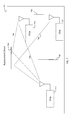
- FIG. 7 shows an embodiment of a system incorporating chips including WCAN transceivers.
- the chips 720 may be located in an enclosure 710 such as a computer chassis. Inside of the enclosure, various transmission barriers 730 may exist which limit the paths of travel for signals from one chip 720 to another. This may also cause direct signals 740 to be transmitted, as well as indirect or reflected signals 750 (also referred to as a multi-path).
- the various transmission barriers 730 and indirect signals 750 make the usage of pulse injection locking valuable. This is an example of a configuration in which the determination of the optimal transmission rate according to the method and systems herein may operate.
- a method for determining an optimal pulse repetition period (PRP) in a system including a wireless transmission device includes providing a first and second an injection-locked transmission system ( 110 , 120 ) (ILT system). The method further includes identifying an optimal PRP ( 650 ) for transmissions using an algorithm executed in a computing system where a bit error rate (BER) of the PRP is less than a bit error rate limit ( 470 ) and the PRP is between two areas of PRPs ( 630 , 640 ) having BERs less than the bit error rate limit, by sending signals from the first ILT system to the second ILT system.
- the identifying includes implementing the algorithm in a microprocessor ( 115 ) within the first ILT system.
- the algorithm includes the following procedures: synchronizing a receiver clock in the second ILT system with a clock of the first ILT system ( 420 ); setting the PRP equal to an impulse duration ( 410 ); increasing the PRP until the BER at the PRP is less than the bit error rate limit ( 470 ); based on the determining that the BER is less than the bit error rate limit, setting the PRP as the optimal PRP( 480 ).
- the method includes determining that a BER of PRPs slightly more that the optimal PRP and PRPs slightly less that the optimal PRP also have a BER less than the bit error rate limit, wherein the determining is occurs before the setting.
- the algorithm includes: synchronizing a receiver clock in the second ILT system with a clock of the first ILT system ( 410 ); setting the PRP equal to an impulse duration ( 420 ); increasing the PRP ( 460 ) until the BER at three consecutive PRPs is less than the bit error rate limit ( 470 ); and based on the determining that the BER is less than the bit error rate limit, setting an average of the three consecutive PRPs as the optimal PRP ( 480 ).
- the first ILT system includes a transmitter ( 110 ) and the transmitter includes a pseudo-random binary sequence transmitter ( 120 ), a non-return to zero to return to zero data converter ( 125 ), a variable pulse window ( 130 ), an injection locked voltage control oscillator ( 135 ), a frequency divider ( 140 ), a combiner ( 145 ), and an antenna ( 150 ).
- a pseudo-random binary sequence transmitter 120
- a non-return to zero to return to zero data converter 125
- a variable pulse window 130
- an injection locked voltage control oscillator 135
- a frequency divider 140
- a combiner 145
- an antenna 150
- the first ILT system includes a receiver ( 120 ) and the receiver includes a receiver antenna ( 155 ), a receiver pulse injection locking system ( 157 ), including a low noise amplifier ( 160 ), a variable amplifier ( 161 ), and an injection locked voltage control oscillator ( 135 ), a phase shifter ( 165 ), a divider ( 140 ) and analog to digital converter ( 170 ).
- the algorithm includes the following: synchronizing a receiver clock in the second ILT system with a clock of the first ILT system; setting the PRP equal to at least five times an impulse duration; decreasing a first time the PRP until the BER at the PRR is greater than the bit error rate limit; decreasing a second time the PRP until the BER at the PRR is less than the bit error rate limit; and based on the determining that the BER is less than the bit error rate limit after decreasing the PRP the first time, setting the PRP as the optimal PRP.
- the PRP is a multiple of a carrier period of the transmissions.
- a system including a microprocessor having a wireless transmission module the microprocessor designed to operate in a wide chip area network system (WCAN system) includes an injection-locked transmission system (ILT system) ( 110 , 120 ).
- the microprocessor includes an algorithm configured to identify a pulse repetition period (PRP) ( 650 ) for transmissions using the ILT system where a bit error rate (BER) of the PRP is less than a bit error rate limit and the PRP is between two areas of PRPs ( 630 , 640 ) having BERs less than the bit error rate limit, by sending signals from the ILT system to the a remote ILT system.
- PRP pulse repetition period
- the algorithm includes instructions for synchronizing a receiver clock in the remote ILT system with a clock of the ILT system ( 420 ); setting the PRP of the ILT system equal to an impulse duration ( 410 ); increasing the PRP ( 460 ) until the BER at the PRP is less than the bit error rate limit ( 470 ); and based on the determining that the BER is less than the bit error rate limit, setting the PRP as the optimal PRP ( 480 ).
- the algorithm includes instructions for determining that a BER of PRPs slightly more that the optimal PRP and PRPs slightly less that the optimal PRP also have a BER less than the bit error rate limit, wherein the determining is occurs before the setting.
- the algorithm includes instructions for synchronizing a receiver clock in the remote ILT system with a clock of the ILT system ( 420 ); setting the PRP of the ILT system equal to an impulse duration ( 410 ); increasing the PRP( 460 ) until the BER at three consecutive PRPs is less than the bit error rate limit ( 470 ); and based on the determining that the BER is less than the bit error rate limit, setting an average of the three consecutive PRPs as the optimal PRP ( 480 ).
- the algorithm includes instructions for synchronizing a receiver clock of the remote ILT system with a clock of the ILT system; setting the PRP equal to an impulse duration, the PRP being very long; decreasing a first time the PRP until the BER at the PRR is greater than the bit error rate limit; decreasing a second time the PRP until the BER at the PRR is less than the bit error rate limit; and based on the determining that the BER is less than the bit error rate limit after decreasing the PRP the first time, setting the PRP as the optimal PRP.
- the ILT system includes a transmitter ( 110 ) and the transmitter includes a pseudo-random binary sequence transmitter ( 120 ), a non-return to zero to return to zero data converter ( 125 ), a variable pulse window ( 130 ), an injection locked voltage control oscillator ( 135 ), a frequency divider ( 140 ), a combiner ( 145 ), and an antenna ( 150 ).
- the first ILT system includes a receiver ( 120 ) and the receiver includes a receiver antenna ( 155 ), a receiver pulse injection locking system ( 157 ), including a low noise amplifier ( 160 ), a variable amplifier ( 161 ), and an injection locked voltage control oscillator ( 135 ), a phase shifter ( 165 ), a divider ( 140 ) and analog to digital converter ( 170 ).
- the PRP is a multiple of a carrier period of transmissions.
Applications Claiming Priority (1)
| Application Number | Priority Date | Filing Date | Title |
|---|---|---|---|
| PCT/IB2012/003091 WO2014102566A1 (en) | 2012-12-24 | 2012-12-24 | Systems and methods for data rate optimization in a wcan system with injection-locked clocking |
Publications (2)
| Publication Number | Publication Date |
|---|---|
| US20140369323A1 US20140369323A1 (en) | 2014-12-18 |
| US9503213B2 true US9503213B2 (en) | 2016-11-22 |
Family
ID=51019955
Family Applications (1)
| Application Number | Title | Priority Date | Filing Date |
|---|---|---|---|
| US13/997,499 Active US9503213B2 (en) | 2012-12-24 | 2012-12-24 | Systems and methods for data rate optimization in a WCAN system with injection-locked clocking |
Country Status (4)
| Country | Link |
|---|---|
| US (1) | US9503213B2 (zh) |
| EP (1) | EP2936758A4 (zh) |
| CN (1) | CN104813628B (zh) |
| WO (1) | WO2014102566A1 (zh) |
Families Citing this family (4)
| Publication number | Priority date | Publication date | Assignee | Title |
|---|---|---|---|---|
| US10211528B2 (en) * | 2015-05-18 | 2019-02-19 | William Marsh Rice University | Fully programmable digital-to-impulse radiating array |
| US10594336B2 (en) * | 2015-10-07 | 2020-03-17 | University College Dublin | Injection locked time mode analog to digital converter |
| US10862423B2 (en) | 2018-01-25 | 2020-12-08 | University College Dublin | Multi-stage sub-THz frequency generator incorporating injection locking |
| CN112165372A (zh) * | 2020-08-12 | 2021-01-01 | 国网江西省电力有限公司经济技术研究院 | 一种配电mimo电力线通信传输方法 |
Citations (4)
| Publication number | Priority date | Publication date | Assignee | Title |
|---|---|---|---|---|
| SU802913A1 (ru) | 1978-05-10 | 1981-02-07 | Предприятие П/Я В-8751 | Способ определени периода повторени пРОизВОльНО МОдулиРОВАННОй иМпульСНОйпОСлЕдОВАТЕльНОСТи |
| US20100040168A1 (en) | 2005-03-29 | 2010-02-18 | Matsushita Electric Industrial Co., Ltd. | Transmitting apparatus, receiving apparatus and communication system |
| US20110169541A1 (en) | 2009-10-22 | 2011-07-14 | Gm Global Technology Operations, Inc. | Method for controlling a device by means of pulse duration modulation and control system |
| EP2360844A1 (en) | 2006-04-26 | 2011-08-24 | Qualcomm Incorporated | Wireless Device Communication with Multiple Peripherals |
-
2012
- 2012-12-24 CN CN201280077280.5A patent/CN104813628B/zh not_active Expired - Fee Related
- 2012-12-24 EP EP12891317.5A patent/EP2936758A4/en not_active Withdrawn
- 2012-12-24 US US13/997,499 patent/US9503213B2/en active Active
- 2012-12-24 WO PCT/IB2012/003091 patent/WO2014102566A1/en active Application Filing
Patent Citations (4)
| Publication number | Priority date | Publication date | Assignee | Title |
|---|---|---|---|---|
| SU802913A1 (ru) | 1978-05-10 | 1981-02-07 | Предприятие П/Я В-8751 | Способ определени периода повторени пРОизВОльНО МОдулиРОВАННОй иМпульСНОйпОСлЕдОВАТЕльНОСТи |
| US20100040168A1 (en) | 2005-03-29 | 2010-02-18 | Matsushita Electric Industrial Co., Ltd. | Transmitting apparatus, receiving apparatus and communication system |
| EP2360844A1 (en) | 2006-04-26 | 2011-08-24 | Qualcomm Incorporated | Wireless Device Communication with Multiple Peripherals |
| US20110169541A1 (en) | 2009-10-22 | 2011-07-14 | Gm Global Technology Operations, Inc. | Method for controlling a device by means of pulse duration modulation and control system |
Non-Patent Citations (3)
| Title |
|---|
| Changhui Hu, Lingli Xia and Patrick Chiang (2011). Transmitter Multi-Path Equalization and Receiver Pulse-Injection Locking Synchronization for Short-Range, Ultrawideband Impulse Radio Communications, Ultra Wideband Communications: Novel Trends-System, Architecture and Implementation, Dr. Mohammad Matin (Ed.), ISBN: 978-953-307-461-0, InTech. * |
| Extended European Search report received for European Patent Application No. 12891317.5, mailed on Jul. 8, 2016, 20 pages. |
| International Search Report and Written Opinion received for PCT Patent Application No. PCT/IB2012/003091, mailed on Sep. 19, 2013, 6 pages. |
Also Published As
| Publication number | Publication date |
|---|---|
| CN104813628A (zh) | 2015-07-29 |
| CN104813628B (zh) | 2018-03-30 |
| US20140369323A1 (en) | 2014-12-18 |
| EP2936758A1 (en) | 2015-10-28 |
| EP2936758A4 (en) | 2016-08-10 |
| WO2014102566A1 (en) | 2014-07-03 |
Similar Documents
| Publication | Publication Date | Title |
|---|---|---|
| US9503213B2 (en) | Systems and methods for data rate optimization in a WCAN system with injection-locked clocking | |
| US7612711B1 (en) | System and method for communicating low data rate information with a radar system | |
| JP5438196B2 (ja) | 遠隔通信装置の間の見通し線(los)距離を判定する方法 | |
| US7822152B2 (en) | Symbol timing detection method and apparatus, and preamble detection method and apparatus | |
| EP2053756B1 (en) | Method of and apparatus for synchronisation | |
| EP2974074B1 (en) | Precision array processing using semi-coherent transceivers | |
| US7403746B2 (en) | Adaptive frame durations for time-hopped impulse radio systems | |
| CN1497863B (zh) | 对超宽带宽电信系统的用户发射数据码元的方法 | |
| KR102342740B1 (ko) | 신호 송수신 방법 및 장치 | |
| RU2341895C2 (ru) | Использование псевдослучайной последовательности частот для снижения помех от пикосетей в многополосной сети ультраширокополосной связи | |
| US20050276319A1 (en) | Wireless communication apparatus and method,and computer program | |
| Klaue et al. | Competition: RedFixHop. | |
| US8155243B2 (en) | Method for the detection of symbols and associated receiver | |
| US7620369B2 (en) | Adaptive frame durations for time-hopped impulse radio systems | |
| US20050078735A1 (en) | Communications systems and methods | |
| Awano et al. | IR-UWB Study for Intra-Satellite Wireless Communication | |
| JP4904596B2 (ja) | ディジタル遅延線中のタップ位置の管理 | |
| US20030161273A1 (en) | Short range RF communication for jet engine control | |
| Xiaolai et al. | The design and performance analysis of inter-chip wireless communication system in instrument based on 60GHz | |
| US20180123775A1 (en) | Transmission device and signal processing method | |
| US20240014852A1 (en) | Reduced interpath interference for ultrawideband (uwb) wireless communication | |
| JP4281898B2 (ja) | ジェットエンジン制御のための近距離rf通信 | |
| RU2273954C1 (ru) | Способ передачи дискретной информации в радиолинии с псевдослучайной перестройкой рабочей частоты | |
| RU2555864C2 (ru) | Система связи с высокой скоростью передачи информации сверхширокополосными сигналами | |
| EP1458138A1 (en) | Short range RF communication for jet engine control |
Legal Events
| Date | Code | Title | Description |
|---|---|---|---|
| AS | Assignment |
Owner name: INTEL CORPORATION, CALIFORNIA Free format text: ASSIGNMENT OF ASSIGNORS INTEREST;ASSIGNORS:GRANKIN, MAKSIM;BAKIN, EUGINE;TURLIKOV, ANDREY;REEL/FRAME:033094/0596 Effective date: 20140516 |
|
| FEPP | Fee payment procedure |
Free format text: PAYOR NUMBER ASSIGNED (ORIGINAL EVENT CODE: ASPN); ENTITY STATUS OF PATENT OWNER: LARGE ENTITY |
|
| STCF | Information on status: patent grant |
Free format text: PATENTED CASE |
|
| MAFP | Maintenance fee payment |
Free format text: PAYMENT OF MAINTENANCE FEE, 4TH YEAR, LARGE ENTITY (ORIGINAL EVENT CODE: M1551); ENTITY STATUS OF PATENT OWNER: LARGE ENTITY Year of fee payment: 4 |