US9502850B2 - Gas laser device - Google Patents
Gas laser device Download PDFInfo
- Publication number
- US9502850B2 US9502850B2 US14/759,942 US201414759942A US9502850B2 US 9502850 B2 US9502850 B2 US 9502850B2 US 201414759942 A US201414759942 A US 201414759942A US 9502850 B2 US9502850 B2 US 9502850B2
- Authority
- US
- United States
- Prior art keywords
- partially cylindrical
- cylindrical member
- optical axis
- gas
- radius
- Prior art date
- Legal status (The legal status is an assumption and is not a legal conclusion. Google has not performed a legal analysis and makes no representation as to the accuracy of the status listed.)
- Expired - Fee Related
Links
Images


Classifications
-
- H—ELECTRICITY
- H01—ELECTRIC ELEMENTS
- H01S—DEVICES USING THE PROCESS OF LIGHT AMPLIFICATION BY STIMULATED EMISSION OF RADIATION [LASER] TO AMPLIFY OR GENERATE LIGHT; DEVICES USING STIMULATED EMISSION OF ELECTROMAGNETIC RADIATION IN WAVE RANGES OTHER THAN OPTICAL
- H01S3/00—Lasers, i.e. devices using stimulated emission of electromagnetic radiation in the infrared, visible or ultraviolet wave range
- H01S3/02—Constructional details
- H01S3/03—Constructional details of gas laser discharge tubes
- H01S3/036—Means for obtaining or maintaining the desired gas pressure within the tube, e.g. by gettering, replenishing; Means for circulating the gas, e.g. for equalising the pressure within the tube
-
- H—ELECTRICITY
- H01—ELECTRIC ELEMENTS
- H01S—DEVICES USING THE PROCESS OF LIGHT AMPLIFICATION BY STIMULATED EMISSION OF RADIATION [LASER] TO AMPLIFY OR GENERATE LIGHT; DEVICES USING STIMULATED EMISSION OF ELECTROMAGNETIC RADIATION IN WAVE RANGES OTHER THAN OPTICAL
- H01S3/00—Lasers, i.e. devices using stimulated emission of electromagnetic radiation in the infrared, visible or ultraviolet wave range
- H01S3/02—Constructional details
- H01S3/03—Constructional details of gas laser discharge tubes
- H01S3/038—Electrodes, e.g. special shape, configuration or composition
-
- H—ELECTRICITY
- H01—ELECTRIC ELEMENTS
- H01S—DEVICES USING THE PROCESS OF LIGHT AMPLIFICATION BY STIMULATED EMISSION OF RADIATION [LASER] TO AMPLIFY OR GENERATE LIGHT; DEVICES USING STIMULATED EMISSION OF ELECTROMAGNETIC RADIATION IN WAVE RANGES OTHER THAN OPTICAL
- H01S3/00—Lasers, i.e. devices using stimulated emission of electromagnetic radiation in the infrared, visible or ultraviolet wave range
- H01S3/14—Lasers, i.e. devices using stimulated emission of electromagnetic radiation in the infrared, visible or ultraviolet wave range characterised by the material used as the active medium
- H01S3/22—Gases
- H01S3/223—Gases the active gas being polyatomic, i.e. containing two or more atoms
- H01S3/2232—Carbon dioxide (CO2) or monoxide [CO]
-
- H—ELECTRICITY
- H01—ELECTRIC ELEMENTS
- H01S—DEVICES USING THE PROCESS OF LIGHT AMPLIFICATION BY STIMULATED EMISSION OF RADIATION [LASER] TO AMPLIFY OR GENERATE LIGHT; DEVICES USING STIMULATED EMISSION OF ELECTROMAGNETIC RADIATION IN WAVE RANGES OTHER THAN OPTICAL
- H01S3/00—Lasers, i.e. devices using stimulated emission of electromagnetic radiation in the infrared, visible or ultraviolet wave range
- H01S3/02—Constructional details
- H01S3/03—Constructional details of gas laser discharge tubes
- H01S3/038—Electrodes, e.g. special shape, configuration or composition
- H01S3/0385—Shape
Definitions
- the present invention relates to a gas laser device for performing laser oscillation or laser amplification with a laser medium gas enclosed in a housing having a sealed structure.
- a conventional orthogonal excitation gas laser device includes a housing having a hermetically sealed structure in which a laser medium gas, such as CO 2 gas, is enclosed.
- the housing is provided with discharging electrodes for discharge exciting the laser medium gas, a heat exchanger for cooling the laser medium gas, and a blower for circulating the laser medium gas.
- discharge excitation is commonly used for excitation caused by collision of electrons during discharge in order to excite (pump) gas molecules which can emit laser light up to an energy level required for stimulated emission.
- the internal space of the oscillator hosing is required to keep a vacuum state of 30 to 60 Torr. Therefore, the oscillator hosing of the laser oscillator is required to have a hermetic sealing performance capable of keeping the vacuum state.
- the housing is commonly provided with a wide opening and a detachable cover member is attached thereto to occlude this opening.
- the cover member of the gas laser device can withstand a load caused when the interior of the housing is kept in a vacuum state, and can hold a hermetic sealing performance capable of keeping the vacuum state, and can have a wide opening area for easy maintenance of components inside the housing.
- prior arts propose a plate-like one or a thin-walled structure having a cover member on which a curved surface expanding internally (See, e.g., Patent document 1) or externally (See, e.g., Patent documents 2 and 5) with respect to the housing is formed.
- gas laser devices which are mainly used for laser machining, have been developed to produce higher power for enhancing the machining performance.
- longer discharging electrodes, larger heat exchangers and larger gas ducts are introduced, thereby resulting in a lengthened housing especially along the optical axis and enlarged height and width of the housing.
- a high atmospheric pressure is applied to the housing and the cover member, hence, which are required to have a higher strength and rigidity.
- Patent Document 2 JP H06-035484 Y (FIG. 1)
- Patent Document 5 WO 2010-134166 A (FIG. 1)
- the large cover member is required to have a larger thickness of the wall for withstanding the atmospheric pressure. Consequently, material cost of the cover member is increased and workability of maintenance is worsened along with the increased weight.
- the present invention provides a gas laser device for generating laser light by exciting a laser gas, including a housing for enclosing the laser gas,
- the housing includes a main body having a frame-like structure with openings formed on both sides thereof, and a pair of cover members detachably attached to cover each of the openings, and
- the main body is provided with a pair of first frame members each extending along the optical axis of the laser light, and a pair of second frame members respectively connecting both ends of the first frame members, and
- each of the cover members includes a partially cylindrical member having an arc-like cross-sectional shape in a plane perpendicular to the optical axis and extending along the optical axis, and a pair of side wall members occluding both ends of the partially cylindrical member, and
- the partially cylindrical member has a bellows portion molded into a shape having peaks and valleys each alternating along the optical axis.
- the side wall member has a curved portion molded into an arc-like shape, and the partially cylindrical member is connected in a tangential direction of the curved portion.
- the side wall member is formed only of the curved portion.
- the radius of curvature of the curved portion varies along the circumferential direction of the partially cylindrical member.
- the radius of the end portion of the partially cylindrical member is larger than the radius of the valley of the bellows portion.
- the radius of the end portion of the partially cylindrical member is equal to the radius of the peak of the bellows portion.
- the cover member has a uniform thickness.
- the partially cylindrical member is provided with a bellows portion molded into a shape having peaks and valleys each alternating along the optical axis, so that buckling strength along the circumferential direction of the partially cylindrical member is improved, hence, a larger and thin-walled cover can be obtained. Consequently, workability is improved and material cost is reduced due to lightweight solution.
- the bellows portion can be elastically deformed along the optical axis, even if warpage occurs during manufacturing the cover member, it can follow a plane to be attached. Therefore, accuracy of dimension can be relaxed and even a larger cover member can be produced at lower cost.
- FIG. 1 is a perspective view of a gas laser device according to Embodiment 1 of the present invention, with one of cover members being detached.
- FIG. 2 is a cross sectional view taken by arrow A in FIG. 1 .
- FIG. 3 is a cross sectional view taken by arrow B in FIG. 1 .
- FIG. 4 is a perspective view showing a state where a flange plate is warped along an optical axis.
- FIG. 5 is a perspective view showing another structure of a cover member according to Embodiment 2 of the present invention.
- FIG. 6 is a cross sectional view taken by arrow C along X-Y plane passing through a center line of a partially cylindrical member.
- FIG. 7 is a perspective view showing yet another structure of a cover member according to Embodiment 3 of the present invention.
- FIG. 8A is a cross sectional view taken by arrow F along a plane passing through a center line of a partially cylindrical member
- FIG. 8B is a cross sectional view taken by arrow D along X-Y plane passing through the center line of the partially cylindrical member.
- FIG. 9 is a cross sectional view taken along X-Y plane passing through a center line of a partially cylindrical member, showing yet another structure of a cover member according to Embodiment 4 of the present invention.
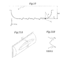
- FIG. 10 is a cross sectional view taken along X-Y plane passing through a center line of a partially cylindrical member, showing yet another structure of a cover member according to Embodiment 5 of the present invention.
- FIGS. 11A and 11B show a state where a partially cylindrical member is buckled.
- FIG. 11A is a perspective view and
- FIG. 11B is a cross sectional view taken by arrow G.
- FIG. 1 is a perspective view of a gas laser device according to Embodiment 1 of the present invention, with one of cover members being detached.
- FIG. 2 is a cross sectional view taken by arrow A in FIG. 1 .
- FIG. 3 is a cross sectional view taken by arrow B in FIG. 1 .
- an optical axis of laser light is defined as X direction
- a height direction perpendicular to the optical axis is defined as Z direction
- a height direction perpendicular to both X and Z directions is defined as Y direction.
- a housing of the gas laser device includes a main body 10 having a frame-like structure with openings formed on both sides thereof, and a pair of cover members 30 detachably attached to cover each of the openings.
- the former and latter are fixed to each other using a securing member, such as bolt 2 , for ensuring a hermetic internal space in which a laser gas is enclosed.
- the main body 10 is provided with an upper plate 12 and a lower plate 13 each extending along X direction, and a pair of side plates 11 respectively connecting both ends of the upper plate 12 and the lower plate 13 .
- These side plates 11 , upper plate 12 and lower plate 13 constitute a frame-like member.
- Each of the openings of this frame-like member is provided with flange plates 14 protruding outward in Z-X plane, respectively.
- On the flange plate 14 an O-ring groove 15 for attaching an O-ring is formed so as to surround the opening. Outside the O-ring groove 15 a plurality of screw holes 16 are formed for fastening the bolt 2 .
- This main body 10 can be fabricated using metal materials, such as steel, stainless steel, aluminum, by hermetically welding the upper plate 12 , the lower plate 13 , the side plates 11 and the flange plates 14 .
- the first excitation unit includes a pair of discharging electrodes 21 A for exciting the laser gas, a blower 23 A for circulating the laser gas, a heat exchanger (not shown) for cooling the laser gas, and a gas duct (not shown) for guiding the laser gas supplied by the blower 23 A toward the discharging electrodes 21 A.
- the laser gas is supplied in ⁇ Y direction and discharge occurs along Z direction and laser light amplified by the laser gas propagates along X direction, thereby constituting a triaxial orthogonal gas laser device.
- the second excitation unit includes a pair of discharging electrodes 21 B for exciting the laser gas, a blower 23 B for circulating the laser gas, a heat exchanger 22 B for cooling the laser gas, and a gas duct 24 B for guiding the laser gas supplied by the blower 23 B toward the discharging electrodes 21 B.
- the laser gas is supplied in Y direction and discharge occurs along Z direction and laser light amplified by the laser gas propagates along X direction, thereby constituting a triaxial orthogonal gas laser device.
- the optical axis of the laser light passing through the first excitation unit is aligned with the optical axis of the laser light passing through the second excitation unit, and the flow directions of the laser gas with respect to the optical axis are opposite to each other, thereby symmetrizing a total gain distribution which is obtained by superposing gain distributions of the excitation units. Consequently, symmetry of the emitted laser beam can be upgraded.
- a partially reflecting mirror 6 and an output window are located at a place where the optical axis of the laser light intersects with one of the side plates 11 , and a fully reflecting mirror (not shown) is located at a place where the optical axis of the laser light intersects with other of the side plates 11 , thereby realizing a laser oscillator which can generate laser light solely.
- transmission windows are located at places where the optical axis of the laser light intersects with both of the side plates 11 , thereby realizing a laser amplifier which can amplify laser light supplied from outside (See Patent Document 6).
- the opening plane of the main body 10 is set to be parallel to the optical axis.
- optical components such as mirror
- the optical components remain stationary. Therefore, work for redoing optical alignment can be omitted.
- the cover member 30 includes a partially cylindrical member 31 having an arc-like cross-sectional shape in Y-Z plane perpendicular to the optical axis and extending along the optical axis, and a pair of side wall members 32 occluding both ends of the partially cylindrical member.
- the partially cylindrical member 31 and the side wall members 32 constitute a semi-cylindrical container, an opening of which is provided with a flange plate 33 protruding outward in Z-X plane.
- the flange plate 33 has a shape suitable to make in contact with the flange plate 14 of the main body 10 , and is provided with a plurality of through holes 3 corresponding to the screw holes 16 of the flange plate 14 .
- This cover member 30 can be fabricated using metal materials, such as steel, stainless steel, aluminum, by hermetically welding the partially cylindrical member 31 , the side wall members 32 and the flange plate 33 .
- this embodiment employs a structure in which the cover member 30 expands externally.
- the interior of the externally expanded space can accommodate components protruding from the opening plane of the main body 10 , resulting in advantage of downsizing the housing correspondingly.
- the partially cylindrical member 31 as shown in FIG. 3 , has a bellows portion 4 molded into a shape having peaks and valleys each alternating along the optical axis.
- This bellows portion 4 can be molded integrally with the partially cylindrical member 31 by stamping.
- the cross section of the housing perpendicular to X direction has a shape in which arc portions each corresponding to the outer walls of the cover member 30 are connected to linear portions each corresponding to the upper plate 12 and the lower plate 13 .
- the cover member 30 can be separated from the main body 10 by releasing the securing member, such as bolt 2 , during maintenance.
- the radius of gyration r is defined as a value that is moment of inertia of area I by cross-sectional area A.
- the arc length of the cylindrical portion of the cover that is, the member length L along a direction in which the large compressive load Fc is exerted is enlarged.
- the slenderness ratio ⁇ is enlarged, and buckling strength becomes smaller.
- a pair of side wall members 32 occluding both ends of the partially cylindrical member 31 can work as a reinforcing rib, resulting in a larger buckling strength.
- the buckling strength is lowered because the central part of the cylindrical portion is far away from the side wall members 32 reinforcing the bending rigidity.
- FIGS. 11A and 11B the central part of the cylindrical portion is likely to buckle.
- some countermeasures such as welding reinforcing ribs or thickening the plate thickness, are required. Consequently, manufacturing cost is increased and maintenance is more difficult along with the increased weight.
- the partially cylindrical member 31 has a bellows portion 4 molded into a shape having peaks and valleys each alternating along the optical axis.
- the moment of inertia of area I of the partially cylindrical member 31 is increased and the slenderness ratio ⁇ is decreased correspondingly, resulting in the enhanced buckling strength and the thinned plate. Consequently, manufacturing cost is decreased and workability is improved due to lightweight members.
- the partially cylindrical member 31 is provided with the bellows portion 4 having flexibility in X-Y plane.
- the bellows portion 4 can deform in a direction of an arrow in FIG. 4 and the flange plate 33 can follow the flange plate 14 of the main body 10 , thereby achieving high airtightness. Further, warpage of the flange plate 33 can be tolerated, leading to increased manufacturing yield and decreased manufacturing cost.
- FIG. 5 is a perspective view showing another structure of a cover member 30 according to Embodiment 2 of the present invention.
- FIG. 6 is a cross sectional view taken by arrow C along X-Y plane passing through a center line 5 of a partially cylindrical member 31 .
- the main body 10 of the housing has the same structure as that of Embodiment 1, redundant description is omitted below.
- a side wall member 32 includes a flat portion extending in Y-Z plane and a curved portion 34 molded into an arc-like shape having a radius of curvature R.
- the partially cylindrical member 31 is connected in a tangential direction of the curved portion.
- the flat portion of the side wall member 32 Since a part of the side wall member 32 is formed as the curved portion 34 , the flat portion of the side wall member 32 has a reduced area. Therefore, even when the atmospheric pressure is exerted, a smaller bending stress occurs in the flat portion, thereby the plate thickness of the flat portion can be thinned. In the curved portion 34 , even when the atmospheric pressure is exerted, no bending stress occurs, hence, the curved portion 34 can be remarkably thinned and lightweight.
- the flat portion is thinned so that the plate thickness of the flat portion is equal to the plate thickness of the cylindrical portion, thereby rendering the plate thickness of the cover member 30 including the flange plate 33 uniform.
- the uniform plate thickness allows it to be molded by stamping with die from one sheet of plate material, thereby achieving remarkable cost reduction by mass production.
- the side wall member 32 can be formed only of the curved portion 34 with a larger radius of curvature R to omit the flat portion. In this case even when the atmospheric pressure is exerted, no bending stress occurs, hence, the cover member 30 can be best thinned.
- FIG. 7 is a perspective view showing yet another structure of a cover member 30 according to Embodiment 3 of the present invention.
- FIG. 8A is a cross sectional view taken by arrow F along a plane passing through a center line 5 of a partially cylindrical member 31
- FIG. 8B is a cross sectional view taken by arrow D along X-Y plane passing through the center line 5 of the partially cylindrical member 31 .
- the main body of the housing has the same structure as that of Embodiment 1, redundant description is omitted below.
- the radius of curvature R of the curved portion 34 varies along the circumferential direction of the partially cylindrical member 31 .
- the curved portion 34 has a radius of curvature Rd
- the curved portion 34 has a radius of curvature Rf ( ⁇ Rd)
- This structure can bring higher degree of freedom in design of shape of the side wall member 32 .
- FIG. 9 is a cross sectional view taken along X-Y plane passing through a center line 5 of a partially cylindrical member 31 , showing yet another structure of a cover member 30 according to Embodiment 4 of the present invention.
- the dashed line in FIG. 9 illustrates the shape of the cover member according to Embodiment 2 shown in FIG. 6 .
- subscript “0” corresponds to Embodiment 2
- subscript “1” corresponds to this embodiment.
- the main body 10 of the housing has the same structure as that of Embodiment 1, redundant description is omitted below.
- a radius Rp 0 from the center line 5 to the connection P 0 is set to be equal to the minimal radius of the partially cylindrical member 31 , that is, the radius R b of the valley of the bellows portion 4 .
- a radius Rp 1 from the center line 5 to the connection P 1 is set to be equal to the maximal radius of the partially cylindrical member 31 , that is, the radius R t of the peak of the bellows portion 4 .
- the radius R t of the valley is larger than the radius R b of the peak by H.
- the gas duct 24 B forms a flow path in which the laser gas can circulate on a plane orthogonal to the optical axis (parallel to the center line 5 ).
- the bending radius of the gas flow path is preferably as large as possible, in other words, the gas duct 24 B preferably has a maximal radius as long as it does not interfere with the cover member 30 .
- the length of the gas duct 24 B along the optical axis is required to be longer than at least the discharge length. In order to have a longer discharge length, the gas duct is required to be longer along the optical axis.
- L 0 and L 1 are distances from the edge portion 25 of the gas duct 24 B to the flat portion of the side wall member 32 .
- the radius of the gas duct 24 B is identical to the radius R b of the valley of the bellows portion 4
- the edge portion 25 is defined as a position at which the gas duct 24 B is in contact with the curved portion 34 .
- L 1 R 0 +H ⁇ (2 ⁇ H ⁇ R 0 +H 2 ) 0.5
- equation (4) can mean L 0 ⁇ L 1 >0, which indicates that (L 0 ⁇ L 1 ) monotonously increases depending on H.
- the length LD 1 of the gas duct 24 B according to this embodiment can be lengthened by equation (4) than the length LD 2 of the gas duct 24 B according to Embodiment 2.
- the gas duct 24 B can be further lengthened. Consequently, the discharge length can be lengthened to produce laser light of higher power without modifying dimensions of the laser gas device.
- FIG. 10 is a cross sectional view taken along X-Y plane passing through a center line 5 of a partially cylindrical member 31 , showing yet another structure of a cover member 30 according to Embodiment 5 of the present invention.
- the main body 10 of the housing has the same structure as that of Embodiment 1, redundant description is omitted below.
- the radius Rp 1 from the center line 5 to the connection P 1 is set to be equal to the radius R t of the peak of the bellows portion 4 .
- the radius Rp 2 from the center line 5 to the connection P 2 is set to be larger than the radius R b of the valley of the bellows portion 4 and smaller than the radius R t of the peak thereof.
- the length of the gas duct 24 B along the optical axis can be also lengthened than that of Embodiment 2. Consequently, the discharge length can be lengthened to produce laser light of higher power without modifying dimensions of the laser gas device.
- the present invention is industrially very useful in that a lightweight and low-cost cover structure can be achieved.
Landscapes
- Physics & Mathematics (AREA)
- Electromagnetism (AREA)
- Engineering & Computer Science (AREA)
- Plasma & Fusion (AREA)
- Optics & Photonics (AREA)
- Chemical & Material Sciences (AREA)
- Chemical Kinetics & Catalysis (AREA)
- Lasers (AREA)
Abstract
Description
R 1 =R 0 +H (1)
R 1 2 =R 0 2 +Y 2 (2)
R 1 −Y=L 1 (3)
L 1 =R 0 +H−(2·H·R 0 +H 2)0.5
L 0 −L 1 =R 0 −L 1 =H((2·R 0 /H+1)0.5−1) (4)
-
- 2 BOLT
- 3 THROUGH HOLE
- 4 BELLOWS PORTION
- 5 CENTER LINE
- 6 PARTIALLY REFLECTING MIRROR
- 10 MAIN BODY
- 11 SIDE PLATE
- 12 UPPER PLATE
- 13 LOWER PLATE
- 14 FLANGE PLATE
- 15 O-RING GROOVE
- 16 SCREW HOLE
- 21A, 21B DISCHARGING ELECTRODE
- 22B HEAT EXCHANGER
- 23A, 23B BLOWER
- 24B GAS DUCT
- 25 EDGE PORTION
- 30 COVER MEMBER
- 31 PARTIALLY CYLINDRICAL MEMBER
- 32 SIDE WALL MEMBER
- 33 FLANGE PLATE
- 34 CURVED PORTION
Claims (7)
Applications Claiming Priority (3)
| Application Number | Priority Date | Filing Date | Title |
|---|---|---|---|
| JP2013063511 | 2013-03-26 | ||
| JP2013-063511 | 2013-03-26 | ||
| PCT/JP2014/055775 WO2014156538A1 (en) | 2013-03-26 | 2014-03-06 | Gas laser device |
Publications (2)
| Publication Number | Publication Date |
|---|---|
| US20150357785A1 US20150357785A1 (en) | 2015-12-10 |
| US9502850B2 true US9502850B2 (en) | 2016-11-22 |
Family
ID=51623526
Family Applications (1)
| Application Number | Title | Priority Date | Filing Date |
|---|---|---|---|
| US14/759,942 Expired - Fee Related US9502850B2 (en) | 2013-03-26 | 2014-03-06 | Gas laser device |
Country Status (5)
| Country | Link |
|---|---|
| US (1) | US9502850B2 (en) |
| JP (1) | JP5980414B2 (en) |
| CN (1) | CN105075035B (en) |
| DE (1) | DE112014001693B4 (en) |
| WO (1) | WO2014156538A1 (en) |
Families Citing this family (1)
| Publication number | Priority date | Publication date | Assignee | Title |
|---|---|---|---|---|
| DE112016001820B4 (en) | 2015-04-20 | 2023-04-27 | Mitsubishi Electric Corporation | LASER DEVICE AND LIGHT-GENERATING DEVICE FOR EXTREMELY ULTRAVIOLET RADIATION |
Citations (10)
| Publication number | Priority date | Publication date | Assignee | Title |
|---|---|---|---|---|
| JPS60254680A (en) | 1984-05-31 | 1985-12-16 | Mitsubishi Electric Corp | Laser oscillator |
| JPH0635484Y2 (en) | 1986-02-25 | 1994-09-14 | 株式会社アマダ | Gas laser oscillator |
| US20020150138A1 (en) * | 2001-04-13 | 2002-10-17 | Pan Xiaojiang J. | Beam seal for line narrowed production laser |
| US6493375B1 (en) * | 2000-02-22 | 2002-12-10 | Tuilaser Ag | Adjustable mounting unit for an optical element of a gas laser |
| US20030193985A1 (en) | 2002-04-11 | 2003-10-16 | Shoichiro Hara | Orthogonally excited-type laser oscillator |
| JP2007294807A (en) | 2006-04-27 | 2007-11-08 | Mitsubishi Electric Corp | Gas laser oscillator |
| US20090078115A1 (en) * | 2005-08-29 | 2009-03-26 | Eiji Yoshida | Gas separator and gas separating method |
| WO2010134166A1 (en) | 2009-05-19 | 2010-11-25 | 三菱電機株式会社 | Gas laser oscillator |
| JP2011159901A (en) | 2010-02-03 | 2011-08-18 | Mitsubishi Electric Corp | Gas laser device |
| US20130168401A1 (en) * | 2010-05-25 | 2013-07-04 | Deevin Avairis | Expandable container |
Family Cites Families (7)
| Publication number | Priority date | Publication date | Assignee | Title |
|---|---|---|---|---|
| GB1016576A (en) | 1962-08-22 | 1966-01-12 | Varian Associates | Optical maser |
| EP0009604A3 (en) * | 1978-10-09 | 1980-04-30 | International Business Machines Corporation | Discharge vessel for a gas laser |
| JPS6032378A (en) * | 1983-08-03 | 1985-02-19 | Toshiba Corp | Oscillation vessel of gas laser |
| JPH01291475A (en) * | 1988-05-19 | 1989-11-24 | Fanuc Ltd | Heat exchanger for gas laser |
| US5881087A (en) * | 1997-04-30 | 1999-03-09 | Universal Laser Systems, Inc. | Gas laser tube design |
| US8814522B2 (en) * | 2007-06-15 | 2014-08-26 | Cymer, Llc | Cross-flow fan impeller for a transversley excited, pulsed, gas discharge laser |
| CN201726033U (en) * | 2010-07-28 | 2011-01-26 | 成都微深科技有限公司 | High-strength winding-resistant carbon dioxide laser |
-
2014
- 2014-03-06 JP JP2015508230A patent/JP5980414B2/en active Active
- 2014-03-06 WO PCT/JP2014/055775 patent/WO2014156538A1/en not_active Ceased
- 2014-03-06 DE DE112014001693.4T patent/DE112014001693B4/en not_active Expired - Fee Related
- 2014-03-06 US US14/759,942 patent/US9502850B2/en not_active Expired - Fee Related
- 2014-03-06 CN CN201480017479.8A patent/CN105075035B/en not_active Expired - Fee Related
Patent Citations (12)
| Publication number | Priority date | Publication date | Assignee | Title |
|---|---|---|---|---|
| JPS60254680A (en) | 1984-05-31 | 1985-12-16 | Mitsubishi Electric Corp | Laser oscillator |
| JPH0635484Y2 (en) | 1986-02-25 | 1994-09-14 | 株式会社アマダ | Gas laser oscillator |
| US6493375B1 (en) * | 2000-02-22 | 2002-12-10 | Tuilaser Ag | Adjustable mounting unit for an optical element of a gas laser |
| US20020150138A1 (en) * | 2001-04-13 | 2002-10-17 | Pan Xiaojiang J. | Beam seal for line narrowed production laser |
| US20030193985A1 (en) | 2002-04-11 | 2003-10-16 | Shoichiro Hara | Orthogonally excited-type laser oscillator |
| JP2003304015A (en) | 2002-04-11 | 2003-10-24 | Mitsubishi Electric Corp | Quadrature pump laser oscillator |
| US20090078115A1 (en) * | 2005-08-29 | 2009-03-26 | Eiji Yoshida | Gas separator and gas separating method |
| JP2007294807A (en) | 2006-04-27 | 2007-11-08 | Mitsubishi Electric Corp | Gas laser oscillator |
| WO2010134166A1 (en) | 2009-05-19 | 2010-11-25 | 三菱電機株式会社 | Gas laser oscillator |
| US20110274132A1 (en) | 2009-05-19 | 2011-11-10 | Mitsubishi Electric Corporation | Gas laser oscillator |
| JP2011159901A (en) | 2010-02-03 | 2011-08-18 | Mitsubishi Electric Corp | Gas laser device |
| US20130168401A1 (en) * | 2010-05-25 | 2013-07-04 | Deevin Avairis | Expandable container |
Non-Patent Citations (2)
| Title |
|---|
| International Search Report (PCT/ISA/210) mailed on Apr. 8, 2014, by the Japanese Patent Office as the International Searching Authority for International Application No. PCT/JP2014/055775. |
| Notification of Transmittal of Translation of the International Preliminary Report on Patentability (Forms PCT/IB/338 and PCT/IB/373) and the Written Opinion of the International Searching Authority (Form PCT/ISA/237) issued on Oct. 8, 2015, by the International Bureau of WIPO in corresponding International Application No. PCT/JP2014/055775. (5 pages). |
Also Published As
| Publication number | Publication date |
|---|---|
| WO2014156538A1 (en) | 2014-10-02 |
| CN105075035A (en) | 2015-11-18 |
| DE112014001693B4 (en) | 2021-09-02 |
| JP5980414B2 (en) | 2016-08-31 |
| DE112014001693T5 (en) | 2015-12-31 |
| JPWO2014156538A1 (en) | 2017-02-16 |
| CN105075035B (en) | 2017-12-29 |
| US20150357785A1 (en) | 2015-12-10 |
Similar Documents
| Publication | Publication Date | Title |
|---|---|---|
| RU2592065C2 (en) | Single-cavity two-electrode discharge chamber and excimer laser | |
| CN102007654B (en) | Diffusion-cooled CO2 laser with flexible housing | |
| CN108463903B (en) | Battery module including belt frame and frame assembly thereof | |
| US9502850B2 (en) | Gas laser device | |
| US7894500B1 (en) | Non-linear waveguided laser channel for a gas laser | |
| JP5911283B2 (en) | Radiation generator | |
| US20150244140A1 (en) | Air-cooled gas lasers with heat transfer resonator optics and associated systems and methods | |
| US8416827B2 (en) | Gas laser oscillator | |
| US10741816B2 (en) | Battery module | |
| CN100474715C (en) | Gas laser vibrator | |
| JP2022073477A (en) | High Frequency Accelerator Cavity and High Frequency Accelerator System | |
| TW202135129A (en) | Radio-frequency excited gas laser | |
| JP2010177419A (en) | Gas laser oscillator | |
| TW201941507A (en) | Conductively-cooled slab laser | |
| US7885310B2 (en) | Gas slab laser | |
| US20210108833A1 (en) | Heat dissipation device and power generator | |
| CN121395019A (en) | Folding pipe | |
| CN119731854A (en) | Assembled battery | |
| CN117397100A (en) | Lightweight battery module housing with improved stiffness and battery pack including same | |
| US4994753A (en) | Synchrotron radiation source | |
| JP3767213B2 (en) | Laser oscillator | |
| ES2235694T3 (en) | CAVITY RESONATOR. | |
| KR20220004552A (en) | Laser oscillator | |
| JPWO2005104309A1 (en) | Laser oscillator and laser processing machine | |
| JPH02295023A (en) | Waveguide airtight window body structure |
Legal Events
| Date | Code | Title | Description |
|---|---|---|---|
| AS | Assignment |
Owner name: MITSUBISHI ELECTRIC CORPORATION, JAPAN Free format text: ASSIGNMENT OF ASSIGNORS INTEREST;ASSIGNORS:FUNAOKA, KOUJI;MATSUMOTO, YASUNARI;SIGNING DATES FROM 20150521 TO 20150526;REEL/FRAME:036039/0841 |
|
| ZAAA | Notice of allowance and fees due |
Free format text: ORIGINAL CODE: NOA |
|
| ZAAB | Notice of allowance mailed |
Free format text: ORIGINAL CODE: MN/=. |
|
| STCF | Information on status: patent grant |
Free format text: PATENTED CASE |
|
| MAFP | Maintenance fee payment |
Free format text: PAYMENT OF MAINTENANCE FEE, 4TH YEAR, LARGE ENTITY (ORIGINAL EVENT CODE: M1551); ENTITY STATUS OF PATENT OWNER: LARGE ENTITY Year of fee payment: 4 |
|
| FEPP | Fee payment procedure |
Free format text: MAINTENANCE FEE REMINDER MAILED (ORIGINAL EVENT CODE: REM.); ENTITY STATUS OF PATENT OWNER: LARGE ENTITY |
|
| LAPS | Lapse for failure to pay maintenance fees |
Free format text: PATENT EXPIRED FOR FAILURE TO PAY MAINTENANCE FEES (ORIGINAL EVENT CODE: EXP.); ENTITY STATUS OF PATENT OWNER: LARGE ENTITY |
|
| STCH | Information on status: patent discontinuation |
Free format text: PATENT EXPIRED DUE TO NONPAYMENT OF MAINTENANCE FEES UNDER 37 CFR 1.362 |
|
| FP | Lapsed due to failure to pay maintenance fee |
Effective date: 20241122 |