US9501210B2 - Information processing apparatus - Google Patents
Information processing apparatus Download PDFInfo
- Publication number
- US9501210B2 US9501210B2 US14/313,454 US201414313454A US9501210B2 US 9501210 B2 US9501210 B2 US 9501210B2 US 201414313454 A US201414313454 A US 201414313454A US 9501210 B2 US9501210 B2 US 9501210B2
- Authority
- US
- United States
- Prior art keywords
- image
- region
- coordinates
- display
- processor
- Prior art date
- Legal status (The legal status is an assumption and is not a legal conclusion. Google has not performed a legal analysis and makes no representation as to the accuracy of the status listed.)
- Active, expires
Links
- 230000010365 information processing Effects 0.000 title claims abstract description 60
- 238000012545 processing Methods 0.000 claims abstract description 133
- 239000000470 constituent Substances 0.000 description 12
- 238000012790 confirmation Methods 0.000 description 11
- 210000003811 finger Anatomy 0.000 description 10
- 238000000034 method Methods 0.000 description 6
- 238000005516 engineering process Methods 0.000 description 5
- 230000006870 function Effects 0.000 description 4
- 238000007792 addition Methods 0.000 description 2
- 230000004075 alteration Effects 0.000 description 2
- 238000010586 diagram Methods 0.000 description 2
- 230000000694 effects Effects 0.000 description 2
- 238000012544 monitoring process Methods 0.000 description 2
- 238000003672 processing method Methods 0.000 description 2
- 238000006467 substitution reaction Methods 0.000 description 2
- 210000003813 thumb Anatomy 0.000 description 2
- 238000004891 communication Methods 0.000 description 1
- 230000007423 decrease Effects 0.000 description 1
- 238000001514 detection method Methods 0.000 description 1
- 210000004247 hand Anatomy 0.000 description 1
- 239000004973 liquid crystal related substance Substances 0.000 description 1
Images


Classifications
-
- G—PHYSICS
- G06—COMPUTING; CALCULATING OR COUNTING
- G06F—ELECTRIC DIGITAL DATA PROCESSING
- G06F3/00—Input arrangements for transferring data to be processed into a form capable of being handled by the computer; Output arrangements for transferring data from processing unit to output unit, e.g. interface arrangements
- G06F3/01—Input arrangements or combined input and output arrangements for interaction between user and computer
- G06F3/048—Interaction techniques based on graphical user interfaces [GUI]
- G06F3/0484—Interaction techniques based on graphical user interfaces [GUI] for the control of specific functions or operations, e.g. selecting or manipulating an object, an image or a displayed text element, setting a parameter value or selecting a range
- G06F3/04842—Selection of displayed objects or displayed text elements
-
- G—PHYSICS
- G06—COMPUTING; CALCULATING OR COUNTING
- G06F—ELECTRIC DIGITAL DATA PROCESSING
- G06F3/00—Input arrangements for transferring data to be processed into a form capable of being handled by the computer; Output arrangements for transferring data from processing unit to output unit, e.g. interface arrangements
- G06F3/01—Input arrangements or combined input and output arrangements for interaction between user and computer
- G06F3/048—Interaction techniques based on graphical user interfaces [GUI]
- G06F3/0481—Interaction techniques based on graphical user interfaces [GUI] based on specific properties of the displayed interaction object or a metaphor-based environment, e.g. interaction with desktop elements like windows or icons, or assisted by a cursor's changing behaviour or appearance
-
- G—PHYSICS
- G06—COMPUTING; CALCULATING OR COUNTING
- G06F—ELECTRIC DIGITAL DATA PROCESSING
- G06F3/00—Input arrangements for transferring data to be processed into a form capable of being handled by the computer; Output arrangements for transferring data from processing unit to output unit, e.g. interface arrangements
- G06F3/01—Input arrangements or combined input and output arrangements for interaction between user and computer
- G06F3/048—Interaction techniques based on graphical user interfaces [GUI]
- G06F3/0487—Interaction techniques based on graphical user interfaces [GUI] using specific features provided by the input device, e.g. functions controlled by the rotation of a mouse with dual sensing arrangements, or of the nature of the input device, e.g. tap gestures based on pressure sensed by a digitiser
- G06F3/0488—Interaction techniques based on graphical user interfaces [GUI] using specific features provided by the input device, e.g. functions controlled by the rotation of a mouse with dual sensing arrangements, or of the nature of the input device, e.g. tap gestures based on pressure sensed by a digitiser using a touch-screen or digitiser, e.g. input of commands through traced gestures
-
- G—PHYSICS
- G06—COMPUTING; CALCULATING OR COUNTING
- G06F—ELECTRIC DIGITAL DATA PROCESSING
- G06F2203/00—Indexing scheme relating to G06F3/00 - G06F3/048
- G06F2203/048—Indexing scheme relating to G06F3/048
- G06F2203/04806—Zoom, i.e. interaction techniques or interactors for controlling the zooming operation
Definitions
- the present disclosure relates to an information processing apparatus that can be operated by designating coordinates on a screen.
- JP 4-359311 A discloses an information processing apparatus that is capable of addressing this problem. This information processing apparatus is capable of enlarging a display region when a user designates a position on image information displayed by its displaying means.
- the present disclosure provides an information processing apparatus that enables a user to designate a region to be enlarged in a display image of a display device by a simple operation.
- An information processing apparatus includes a display device configured to display a first image, a coordinate input device configured to input coordinates on the first image, and a processor configured to perform processing based on input to the coordinate input device.
- the processor specifies a part of a region on the first image as a specific region, based on coordinates of two points that are input to the coordinate input device, generates a second image that is obtained by enlarging the specific region at a predetermined magnification, and causes the display device to superimpose and display the second image on the first image with the second image occupying a part of the first image.
- a user is able to designate a region to be enlarged in a display image of a display device by a simple operation.
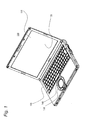
- FIG. 1 is a view showing an external appearance of an information processing apparatus in a first embodiment.
- FIG. 2 is a block diagram showing the configuration of the information processing apparatus in the first embodiment.
- FIG. 3 shows a screen shot of a first image in the first embodiment.
- FIG. 4 shows a flowchart for describing enlargement display processing in the first embodiment.
- FIG. 5A shows a screen shot of the first image illustrating an example of coordinate determination processing of two points.
- FIG. 5B is a view for describing a rectangular region in an example of calculation processing of a specific region.
- FIG. 5C is a view for describing an enlargement assumption region in an example of the calculation processing of the specific region.
- FIG. 5D shows an example of a display by superimposition display processing of an enlarged image.
- FIG. 6 is a flowchart for describing the coordinate determination processing of two points in the first embodiment.
- FIG. 7 shows a screen shot of the first image showing another example of the coordinate determination processing of two points.
- FIG. 8 is a flowchart for describing the calculation processing of the specific region in the first embodiment.
- FIG. 9 shows a screen shot of the first image showing another, example of the calculation processing of the specific region in the first embodiment.
- FIG. 10A is a view for describing an example of the processing of shifting the enlarged image.
- FIG. 10B shows an example of the display by the processing of shifting the enlarged image.
- FIG. 11 shows a flowchart for describing calculation processing of a specific region according to a second embodiment.
- FIGS. 1-10B a first embodiment is described with reference to FIGS. 1-10B .
- FIG. 1 is a view showing the external appearance of an information processing apparatus in the first embodiment.
- An information processing apparatus 100 performs predetermined information processing based on an installed OS (operating system).
- the present embodiment describes an example in which the present disclosure has been applied to a notebook personal computer (PC) as an example of the information processing apparatus.
- the information processing apparatus to which the present disclosure is applied is not limited to a notebook personal computer.
- the present disclosure can also be applied to the information processing apparatus such as a laptop PC, a tablet PC, a smartphone, and the like.
- the information processing apparatus 100 includes a display device 110 , a touch panel 120 , a keyboard 130 , a touchpad 140 , and buttons 150 .
- the display device 110 displays still images or moving images.
- a liquid crystal display is used as the display device 110 in the present embodiment, but different kinds of the display device can be used (e.g. organic electroluminescent display).
- the touch panel 120 is a sensor that is integrally incorporated in the display device 110 .
- a user of the information processing apparatus 100 is able to operate the information processing apparatus 100 by way of the touch panel 120 by touching the display surface of the display device 110 .
- the keyboard 130 receives key input from the user of the information processing apparatus 100 .
- the touchpad 140 receives input through touching operation from the user of the information processing apparatus 100 .
- the user is able to operate the information processing apparatus 100 by touching the touchpad 140 .
- the buttons 150 are input devices with which a pressing operation is possible.
- the information processing apparatus 100 of the present embodiment includes a plurality of the buttons 150 .
- the user of the information processing apparatus 100 is able to operate the information processing apparatus 100 by operating the buttons 150 .
- Operations that can be executed by means of the buttons 150 include, for example, left-click and right-click operations, a double-click operation, and the like.
- the touch panel 120 , the keyboard 130 , and the touchpad 140 are able to function as coordinate input devices for inputting coordinates of the display screen of the display device 110 .
- the touch panel 120 functions as a coordinate input unit.
- moving a cursor continuously by moving a finger across the touch panel 120 or the touchpad 140 for example, or by operating a direction key of the keyboard 130 is referred to as a drag operation.
- FIG. 2 is a block diagram showing the configuration of the information processing apparatus in the first embodiment
- the information processing apparatus 100 further includes a processor 210 , a storage device 220 , and a bus 230 .
- the processor 210 executes programs stored in the storage device 220 .
- the processor 210 controls the constituent elements configuring the information processing apparatus 100 by executing the programs. For example, by executing a predetermined program, the processor 210 causes the display device 110 to display image information stored in the storage device 220 .
- the storage device 220 temporarily or permanently stores data required for the information processing apparatus 100 to perform information processing.
- the storage device 220 stores programs and numerical values to which the programs refer.
- a non-volatile memory or a HDD (hard disk drive) for example is used as the storage device 220 .
- An OS is stored in the storage device 220 .
- the OS provides to the user a system which allows the program (software) to handle the constituent elements provided in the information processing apparatus 100 .
- a program for enlargement display processing described hereinafter is stored in the storage device 220 .
- the storage device 220 has a register 221 that holds a flag showing a sense state of an input to the touch panel 120 .
- the flag of the register 221 is set to H (a high level), when the touch panel 120 senses a touch by the user or the like. On the other hand, when the touch panel 120 does not sense a touch by the user or the like, the flag of the register 221 is set to L (a low level).
- the register 221 holds a plurality of flags, to sense a plurality of coordinates that are input to the touch panel 120 .
- the register 221 may not be included in the storage device 220 , and may be provided inside the touch panel 120 .
- the bus 230 is a communication path for control signals and data transmitted and received by the constituent elements configuring the information processing apparatus 100 . Control signals and data are transmitted and received among the constituent elements of the information processing apparatus 100 via the bus 230 .
- the display device 110 , the touch panel 120 , the processor 210 , and the storage device 220 are connected to the bus 230 .
- the processor 210 transmits and receives various signals with the constituent elements configuring the information processing apparatus 100 , and thereby controlling the constituent elements.
- the touch panel 120 sends coordinate information to the processor 210 via the bus 230 .
- the coordinate information is information relating to the coordinates of a position that the user has touched on the touch panel 120 .
- the processor 210 executes a program using received coordinate information to generate various signals and image data.
- Generated signals are transmitted to the storage device 220 via the bus 230 , and are stored as data in the storage device 220 .
- generated image data is transmitted to the display device 110 via the bus 230 .
- the display device 110 displays an image represented by the image data. It should be noted that, although not shown, signals corresponding to information input by the user in the keyboard 130 , the touchpad 140 , or the buttons 150 are also transmitted to the processor 210 via the bus 230 .
- the processor 210 causes the display device to display a first image.
- FIG. 3 shows a screen shot of the first image.
- a first image 410 is displayed by functions of the OS and the like.
- the first image 410 there are pointed out a desktop screen, a screen of a web browser, and a screen of paint software.
- the first image 410 is displayed in a whole of a display region 111 of the display device 110 in the present embodiment, the first image 410 may be displayed in only a part of the display region 111 of the display device 110 .
- a size of the first image 410 is defined by a width and a height.
- a width direction of the first image 410 and the display region 111 of the display device 110 is set as an x direction, and a height direction of the first image 410 and the display region 111 of the display device 110 is set as a y direction.
- the first image 410 includes an icon 430 .
- the information processing apparatus 100 can perform enlargement display processing.
- the enlargement display processing is processing of displaying an enlarged image which is obtained by enlarging a part of the region of the first image (the first image 410 shown in FIG. 3 , for example), by superimposing the enlarged image on the first image, according to a user operation to the touch panel 120 .
- the enlargement display processing will be described below.
- FIG. 4 shows a flowchart for describing the enlargement display processing.
- FIGS. 5A to 5D show an example of a screen shot of the first image in a series of processing of the enlargement display processing.
- Each processing in the flowchart of FIG. 4 is realized by the processor 210 executing a program stored in the storage device 220 .
- a description will be made by taking an example that, before the enlargement display processing is started, the first image 410 as shown in FIG. 3 is displayed in the display device 110 .
- the enlargement display processing may be started by an explicit execution of a predetermined program by the user, or may be started by a background processing function of the OS.
- the processor 210 performs coordinate determination processing of two points (step S 110 ).
- the coordinate determination processing of two points is processing of determining the coordinates of two points on the first image 410 according to the input to the touch panel 120 , in order to receive from the user, designation of a region which becomes an enlargement display target.
- FIG. 5A shows a screen shot of the first image illustrating an example of the coordinate determination processing of two points.
- the user of the information processing apparatus 100 touches two points (coordinates of a point P 1 and coordinates of a point P 2 ) that sandwich the icon 430 .
- the processor 210 determines the coordinates of designated two points P 1 and P 2 based on input by such user's touch operation.
- the processor 210 performs calculation processing of a specific region (step S 120 ).
- the calculation processing of a specific region is processing of calculating the specific region based on the coordinates of the two points determined by the coordinate determination processing of two points in step S 110 .
- the specific region is a part of the first image that becomes an enlargement display target in the enlargement display processing.
- FIGS. 5B and 5C are views for describing an example of the calculation processing of a specific region based on the coordinates of the two points P 1 and P 2 shown in FIG. 5A .
- the processor 210 calculates a rectangular region S 1 shown in FIG. 5B based on the coordinates of the two points P 1 and P 2 .
- the rectangular region S 1 is a region of a rectangular that is defined by using the coordinates of the two points P 1 and P 2 as end points of a diagonal line.
- the processor 210 decides, by using an enlargement assumption region Q 1 as shown in FIG.
- the enlargement assumption region Q 1 is a virtual region for confirming a size of an enlarged image that is generated by later enlargement processing of a specific region (step S 130 ).
- the processor 210 specifies the rectangular region S 1 as a specific region.
- the processor 210 specifies a specific region inside the rectangular region S 1 , as described later.
- the processor 210 performs the enlargement processing of a specific region (step S 130 ).
- the enlargement processing of a specific region is processing of generating image information (a second image) of an enlarged image, by enlarging the image of the specific region specified in the calculation processing of a specific region in step S 120 .
- the processor 210 performs superimposition display processing of an enlarged image (step S 140 ).
- the superimposition display processing of an enlarged image is processing of superimposing and displaying an enlarged image on the first image, based on the image information generated in the enlargement processing of a specific region in step S 130 .
- FIG. 5D shows an example of a display by the superimposition display processing of an enlarged image, following the calculation processing of a specific region (step S 120 ).
- the processor 210 causes an enlarged image E 1 obtained by enlarging the rectangular region S 1 shown in FIG. 5C to be superimposed and displayed on the first image 410 so that the enlarged image E 1 occupies a part of the first image 410 , as shown in FIG. 5D .
- the enlarged image E 1 includes an icon 440 obtained by enlarging the icon 430 sandwiched by the user between the coordinates of the two points P 1 and P 2 in FIG. 5A .
- the user can designate a part of the region that is desired to be enlarged in the first image, by a simple operation of inputting the coordinates of two points.
- the information processing apparatus 100 superimposes and displays the image of the enlarged designated region on the first image so that the enlarged image is within the display region ill of the display device 110 .
- the pieces of processing in steps S 110 to S 140 will be described in detail below.
- the coordinate determination processing of two points (step S 110 ) in FIG. 4 will be described.
- the processor 210 determines the coordinates of two points that are included in the first image 410 based on the input of a plurality of coordinates that the user of the information processing apparatus 100 inputs.
- the operation for inputting the coordinates of two points is an operation that the user, for example, touches two points on the touch panel 120 with fingers, and thereafter, releases the fingers off the touch panel 120 .
- the processor 210 determines the coordinates of the two points based on the input of coordinates of the two points. The user can simply perform the above operation, by substantially simultaneously touching the two points on the touch panel 120 , for example, using the thumb and the middle finger.
- the processor 210 determines coordinates of two points by performing exceptional processing.
- Such an exceptional operation corresponds to an operation by the user to input coordinates of a third point, or an operation by the user to release the touched finger off in the middle of the operation to input other coordinates, for example.
- a processing method by which the processor 210 determines coordinates of two points will be described in detail.
- FIG. 6 is a flowchart for describing the coordinate determination processing of two points.
- the processor 210 starts the coordinate determination processing of two points in step S 110 in FIG. 4 .
- the processor 210 detects an input of coordinates of a first point (first coordinates) on the touch panel 120 (step S 210 ). Specifically, when the user first touches on the touch panel 120 , the touch panel 120 then senses the touched coordinates. Subsequently, the touch panel 120 generates coordinate information that shows the sensed coordinates in a format in which the processor 210 can process the coordinate information. The touch panel 120 transmits the generated coordinate information to the processor 210 via the bus 230 . The processor 210 receives the coordinate information of the input coordinates of the first point from the touch panel 120 . The processor 210 records the received first coordinate information into the storage device 220 .
- the processor 210 decides whether the input (input operation) of the first coordinates continues (step S 220 ).
- a state that the input of the coordinates continues is a state that the user keeps touching the touch panel 120 , for example.
- the touch panel 120 Upon sensing a touch by the user or the like, the touch panel 120 generates coordinate information indicating the sensed coordinates, and also sets the flag of the register 221 to H. On the other hand, upon sensing a release of a touch on the touch panel 120 , the touch panel 120 sets the flag of the register 221 to L.
- the processor 210 monitors the flag of the register 221 , and decides that the input of coordinates by the user or the like continues, during a period in which the flag of the register 221 is kept being set to H. On the other hand, when the flag of the register 221 is changed over from H to L, the processor 210 decides that the input of coordinates by the user or the like does not continue and that the input is released.
- the processor 210 When the input of the coordinates of the first point does not continue (NO in step S 220 ), the processor 210 returns to the processing in step S 210 .
- the processor 210 detects an input of coordinates of a second point (second coordinates) onto the touch panel 120 (step S 230 ). Because a method of detecting the coordinates of the second point is identical with the method of detecting the input of the coordinates of the first point in step S 210 , a detailed description of the method of detecting the coordinates of the second point will be omitted.
- the processor 210 records the input second coordinate information into the storage device 220 .
- the processor 210 decides whether there is an input of coordinates of a third point.
- the processor 210 detects the input of coordinates of the third point, by deciding whether coordinates different from the coordinates of the two points input in the processing in steps S 210 and S 230 are input.
- the processor 210 returns to the processing in step S 210 . That is, the processor 210 returns to a state that no coordinates are input.
- the information processing apparatus 100 executes an application for executing specific processing by simultaneously receiving inputs of coordinates of three or more points on the touch panel 120 , it is possible to avoid a competition between the processing described in the present disclosure and the specific processing of the application.
- the processor 210 decides whether the input of the coordinates of either the first point or the second point is released or not (step S 250 ). Specifically, the processor 210 decides a release of the input of coordinates, by monitoring the flag of the register 221 , in a similar manner to that in step S 220 .
- the processor 210 decides whether there is a new input of coordinates (new coordinates) or not (step S 260 ).
- the processor 210 detects the new input of coordinates, by deciding whether there is an input of coordinates different from the other input of coordinates that is not released in step S 250 out of the two points that are detected in steps S 210 and S 230 .
- Detection of a new input of coordinates is executed until the other input of coordinates in step S 250 is released (NO in step S 260 ).
- the processor 210 detects a release of the other input of coordinates in step S 250 , by monitoring the flag of the register 221 , in a similar manner to that of step S 220 (step S 270 ).
- step S 250 When the other input of coordinates in step S 250 is released (YES in step S 270 ), the processor 210 determines the coordinates of the two inputs that are held in the storage device 220 , as the coordinates of the two points (step S 280 ), and ends the coordinate determination processing of two points.
- the processor 210 performs subsequent calculation processing of a specific region, enlargement processing of the specific region, and superimposition display processing of an enlarged image using the determined coordinates of the two points.
- step S 260 upon detecting a new input of coordinates (YES in step S 260 ), the processor 210 replaces the coordinates released in step S 250 with the new coordinates (step S 265 ). Specifically, the processor 210 rewrites the released coordinate information out of the first and second coordinate information that are held in the storage device 220 , with coordinate information of the new input of coordinates, and performs the processing in step S 250 again.
- FIG. 7 shows an example that, after the user touches the coordinates of the points P 1 and P 2 , the user cancels the touch of the coordinates of P 1 , and touches the coordinates of the point P 3 . It is assumed that until the user touches the coordinates of the point P 3 , a value of the first coordinate information is the value of the coordinates of the point P 1 , and a value of the second coordinate information is the value of the coordinates of the point P 2 . After the user touches the coordinates of the point P 3 , the processor 210 rewrites the value of the first coordinate information that is held in the storage device 220 , from the value of the coordinates of the point P 1 to the value of the coordinates of the point P 3 (step S 265 ).
- the processor 210 decides whether the inputs (touches) of the coordinates of the points P 3 and P 2 are released (steps S 250 to S 270 ). After the user releases the inputs (touches) of both coordinates of the points P 3 and P 2 , the processor 210 determines the coordinates of the points P 3 and P 2 as the coordinates of the two points (step S 280 ). As a result, the user can change the region to be designated as an enlargement display target, from the rectangular region S 1 shown in FIG. 5B to a rectangular region S 1 ′ shown in FIG. 7 .
- step S 265 when the user made an error in selecting a position to be touched on the touch panel 120 in the input of coordinates of the first point or the second point, the user can release only the wrong input of coordinates. At this time, by touching again a desired position, the user can correct the designated position to continue the processing.
- coordinates of two points that are determined by the coordinate determination processing of two points are the coordinates at the time of the input of coordinates, that is, the coordinates of points touched by fingers of the user at an input timing.
- these coordinates are acceptable. That is, coordinates that are touched at different timings of the fingers of the user, or coordinates of a point with a predetermined distance from an actually touched point, may be also determined as the coordinates of two points.
- the processor 210 proceeds to the process of the calculation processing of a specific region (step S 120 ) in FIG. 4 .
- the calculation processing of a specific region (step 120 ) in FIG. 4 will be described.
- the processor 210 calculates a rectangular region defined by the coordinates of the two points on the first image determined in step S 110 .
- the processor 210 specifies a specific region that becomes an enlargement display target, from the calculated rectangular region.
- a processing method for the processor 210 to calculate a specific region will be described.
- FIG. 8 is a flowchart for describing calculation processing of a specific region.
- the processor 210 calculates a rectangular region that has, as a diagonal line, a straight line connecting the two points determined in step S 110 with each other (step S 310 ). In the processing in step S 310 , the processor 210 calculates a size of the rectangular region. A position of the rectangular region is not yet specified in the processing in step S 310 .
- the coordinates of P 1 and the coordinates of P 2 are determined as the coordinates of the two points.
- the processor 210 calculates, in step S 310 , the rectangular region S 1 having, as a diagonal line, a straight line connecting the coordinates of the two points P 1 and P 2 with each other as shown in FIG. 5B .
- a height direction and a width direction of the rectangular region S 1 are identical with a height direction and a width direction of the display region 111 of the display device 110 .
- step S 320 the processor 210 calculates the enlargement assumption region Q 1 which is obtained by enlarging the rectangular region S 1 at a predetermined magnification (hereafter, referred to as “confirmation magnification”) (see FIG. 5C ).
- the enlargement assumption region Q 1 is a virtual region for confirming a size of the enlarged image generated by the enlargement processing of a specific region (step S 130 ), and the confirmation magnification is a predetermined magnification for calculating the enlargement assumption region.
- the processor 210 performs a comparison decision of comparing between a width of the enlargement assumption region Q 1 and a reference value for width (step S 330 ).
- This comparison is performed in a pixel unit, for example.
- the reference value for width is set to a value of the width of the display region 111 of the display device 110 , in the present embodiment.
- the processor 210 calculates again a rectangular region S 2 so that the enlargement assumption region Q 1 has a width of a value obtained by dividing the reference value for width by the confirmation magnification (step S 340 ).
- the processor 210 performs the processing in step S 350 , without changing the rectangular region S 1 .
- the processor 210 performs a comparison decision of comparing between a height of the enlargement assumption region Q 1 and a reference value for height (step S 350 ).
- This comparison is performed in a pixel unit, for example.
- the reference value for height is set to a value of the height of the display region 111 of the display device 110 , in the present embodiment.
- the processor 210 calculates again the rectangular region S 2 so that the enlargement assumption region Q 1 has a height of a value obtained by dividing the reference value for height by the confirmation magnification (step S 360 ).
- the processor 210 performs the processing in step S 370 , without changing the rectangular region S 1 .
- the height (and the width) of the enlargement assumption region Q 1 is equal to or smaller than the height (and the width) of the display region 111 of the display device 110 . Therefore, in the example of FIGS. 5A to 5D , the pieces of processing in step S 340 and step S 360 are not performed.
- FIG. 9 is a view showing an example that the height of the rectangular region is changed in step S 360 .
- the difference between the example of FIG. 9 and the example of FIGS. 5A to 5D is a magnification for enlarging the rectangular region S 1 .
- processing of changing the height of the rectangular region in step S 360 will be described in detail with reference to FIG. 9 .
- a height H 0 of the display region 111 of the display device 110 that is set as the reference value for height is 1200 pixels.
- a height h 1 of the rectangular region S 1 that is calculated by the coordinates of the input two points is assumed to be 500 pixels.
- the processor 210 decides that the height H 1 of the enlargement assumption region Q 1 ′ is larger than the height H 0 of the display region 111 of the display device 110 (YES in step S 350 ). Therefore, the processor 210 performs processing of reducing the height h 1 of the rectangular region S 1 (step S 360 ).
- the processor 210 calculates a height h 2 , by dividing the height H 0 (1200 pixels) of the display region 111 of the display device 110 by the confirmation magnification 3.
- the processor 210 recalculates the rectangular region S 2 , to have the height h 2 .
- the recalculated height of an enlargement assumption region Q 2 of the rectangular region S 2 becomes 1200 pixels that is the same as the height H 0 of the display region 111 of the display device 110 , and becomes a height that can be displayed inside the display region 111 of the display device 110 .
- the recalculated height of the enlargement assumption region Q 2 of the rectangular region S 2 may not be actually calculated.
- step S 370 the processor 210 arranges the rectangular region so that a center of the rectangular region coincides with a midpoint of the coordinates of the designated two points.
- the rectangular region is shown by making the centers of the rectangular region S 1 and the enlargement assumption region Q 1 coincide with the midpoint of the coordinates of the designated two points P 1 and P 2 .
- the processor 210 specifies the arranged rectangular region as a specified region (step S 380 ), and ends the calculation processing of a specific region. After ending the calculation processing of a specific region, the processor 210 performs the enlargement processing of a specific region (step S 130 ) in FIG. 4 .
- step S 140 When the processing in step S 340 or step S 360 is performed, in the later superimposition display processing of an enlarged image (step S 140 ), there is a case where an edge of the enlarged image coincides with an edge of the display region 111 of the display device 110 . If the edge of the enlarged image coincides with the edge of the display region 111 of the display device 110 , there is a risk that the operation to the first image is limited. For example, when a condition for starting a predetermined program is linked to an operation that is performed to an end of the first image, the operation to the first image is limited. Therefore, in the processing shown in FIG.
- the calculation processing of the specific region may be performed, by setting a reference value for width and/or a reference value for height to a value smaller than the width and/or the height of the display region 111 of the display device 110 .
- step S 130 The enlargement processing of a specific region (step S 130 ) will be described.
- the processor 210 enlarges a specific region specified by the calculation processing of a specific region, at a predetermined magnification (hereafter, referred to as “display magnification”).
- the display magnification is larger than one times.
- the processor 210 generates image information showing an enlarged image that is obtained by enlarging the specific region at the display magnification.
- the generated image information is stored in the storage device 220 .
- the display magnification that is used in the enlargement processing of a specific region in step S 130 is set identical with or smaller than the confirmation magnification that is used in step S 120 , for example.
- the display magnification that is used in step S 130 is larger than the confirmation magnification used in step S 120 , there is a risk that the enlarged image cannot be within the display region ill of the display device 110 . By the above setting, such a situation can be avoided.
- the superimposition display processing of an enlarged image (step S 140 ) in FIG. 4 will be described.
- the processor 210 causes the display device 110 to superimpose and display, on the first image, an enlarged image (the second image) of the image information generated by the enlargement processing of a specific region in step S 130 .
- the processor 210 adjusts a position of the enlarged image so that the enlarged image is within the display region 111 of the display device 110 . Specifically, assuming that on the first image, the enlarged image is arranged at a position so that the center of the specific region and the center of the enlarged image coincide with each other, the processor 210 decides whether the enlarged image is entirely within the display region 111 of the display device 110 .
- the processor 210 causes the display device 110 to display the enlarged image at the above position.
- the enlarged image E 1 does not extend outside the display region 111 of the display device 110 , at a position where the center of the enlarged image E 1 and the center of the rectangular region S 1 coincide with each other. Therefore, the display device 110 superimposes and displays the enlarged image E 1 at the above position on the first image 410 .
- the processor 210 shifts the position of the enlarged image so that whole of the enlarged image is within the region of a part of the display region 111 of the display device 110 within the display region 111 of the display device 110 .
- the processor 210 moves the enlarged image to the right by an extending length of the enlarged image outside the display region 111 of the display device 110 .
- an enlarged image E 2 extends outside the display region 111 of the display device 110 to the left side (i.e., in the negative x direction) by a distance D 1 .
- the processor 210 shifts the enlarged image E 2 along the positive x direction, by the extending distance D 1 of the enlarged image outside the display region 111 of the display device 110 , as shown in FIG. 10B .
- the processor 210 When any part of the enlarged image extends outside the display region 111 of the display device 110 to an upside, a right side, and a downside, the processor 210 similarly performs the processing of shifting the enlarged image to a direction opposite to the extending direction of the enlarged image outside the display region 111 of the display device 110 .
- the processor 210 may perform processing of shifting the edge of the enlarged image, from a position where the edge of the enlarged image and the edge of the display region 111 of the display device 110 coincide with each other, to inside the display region 111 of the display device 110 by a predetermined distance. Further, the processor 210 may perform processing of shifting the enlarged image by an extending length in a similar manner to that in FIGS. 10A and 10B , based on a region which is inside of the display region 111 by a predetermined distance from the end of the display region 111 of the display device 110 .
- the processor 210 erases the displayed enlarged image.
- the processor 210 When coordinates on the first image 410 are designated by a coordinate input device such as the touch panel 120 , the touch pad 140 , and the buttons 150 , the processor 210 performs specific processing. For example, when coordinates on the icon 430 displayed in the first image 410 are designated by a double click, the processor 210 performs information processing of starting a predetermined program.
- the processor 210 When the enlarged image obtained by the enlargement display processing is being superimposed and displayed on the first image 410 in such a manner that the enlarged image occupies a part of the first image 410 , the processor 210 performs a mirroring operation of relating some operation such as a starting of the program to coordinates of the enlarged image. Specifically, when coordinates are designated to the enlarged image by the coordinate input device, the processor 210 regards that the corresponding coordinates are designated in the specific region, and performs information processing corresponding to the coordinate input on the specific region. For example, in FIG. 5D , when an icon image 440 displayed in the enlarged image E 1 is double-clicked, the processor 210 regards that the icon 430 (see FIG. 5B ) on the specific region as an enlargement source is double-clicked, and performs information processing corresponding to the double-click of the icon 430 .
- the user can perform an operation to the image of the enlargement source, by designating the coordinates on the enlarged image.
- the user can intuitively operate the information processing apparatus 100 .
- the information processing apparatus 100 has the display device 110 configured to display a first image, the touch panel 120 configured to input the coordinates on the first image 410 , and the processor 210 configured to perform processing based on input to the touch panel 120 .
- the processor 210 specifies a part of the region on the first image 410 , as a specific region, based on coordinates of two points input to the touch panel 120 .
- the processor 210 generates a second image obtained by enlarging the specific region at a predetermined display magnification.
- the processor 210 causes the display device 110 to superimpose and display a second image on the first image 410 with the second image occupying a part of the first image 410 .
- the information processing apparatus 100 can display an enlarged image for the user, by enlarging a region specified by the input. Therefore, the user can designate a region to be enlarged by a simple operation to cause the display device to display a part of the region of the display region 111 .
- the coordinate input device is the touch panel 120 arranged in the display device 110 . Accordingly, the user can designate the same coordinates as the coordinates of a position touched on the display device 110 , and can intuitively operate the touch panel 120 .
- the processor 210 detects both the coordinates of the first point P 1 input by the touch to the touch panel 120 and the coordinates of the second point P 2 input by the touch to the touch panel 120 during a period when the input of the coordinates of the first point P 1 continues (step S 220 ), and determines the coordinates of the two points P 1 and P 2 based on the coordinates of the first and second points P 1 and P 2 .
- the information processing apparatus 100 After a user's natural operation of substantially simultaneously touching the display device 110 with two fingers or placing the thumb after placing the middle finger on the display device 110 , the information processing apparatus 100 generates the enlarged image based on the coordinates of the two points corresponding to the two fingers. Therefore, the user can intuitively clearly designate the region that is desired to be enlarged, with one hand or two hands.
- step S 260 when new coordinates of a point P 3 are input to the touch panel 120 (step S 260 ) after the input of the coordinates of one of the two points P 1 and P 2 is released, the processor 210 replaces the released the coordinates with the new coordinates of the point P 3 (step S 265 ).
- the user when the user makes an error in selecting a position to be touched on the touch panel 120 in the input of the coordinates of the first point or the second point, the user can release the wrong designation, and can correct the designated position, by touching a new point of coordinates.
- the processor 210 arranges the enlarged image E 1 , at a position where the center of the enlarged image E 1 and the center of the rectangular region S 1 coincide with each other on the first image 410 . If any part of the arranged enlarged image E 2 extends outside a whole of the display region 111 of the display device 110 , the processor 210 shifts a position of the arranged enlarged image E 2 to a direction opposite to a specific direction. The specific direction is the extending direction of the enlarged image E 1 outside the display region 111 of the display device 110 .
- the processor 210 causes the display device 110 to display the enlarged images E 1 and E 2 , at the above positions on the first image 410 (step S 140 ).
- the processor 210 calculates the rectangular region S 1 as the designated region defined by the coordinates of the two points P 1 and P 2 , on the first image 410 (step S 310 ), and specifies the specific region within a range of the rectangular region S 1 .
- the processor 210 specifies a whole or a part of the center of the rectangular region S 1 as the specific region so that the center of the rectangular region S 1 and the center of the specific region coincide with each other (step S 370 ). Accordingly, the user can clearly designate a region that becomes an enlargement target, by inputting the coordinates of points that sandwich the image which is desired to be enlarged.
- the processor may calculate a circular region, an elliptical region, a square-shaped region having round angles, and the like, using a straight line formed by connecting between coordinates of two points as a diameter.
- the processor 210 when an enlarged size of the rectangular region S 1 obtained by magnifying a size of the rectangular region S 1 at the confirmation magnification is equal to or smaller than a whole of the display region 111 of the display device 110 , the processor 210 specifies the rectangular region S 1 as the specific region. On the other hand, when a size of the rectangular region S 1 enlarged at the confirmation magnification is larger than a whole of the display region 111 of the display device 110 , the processor 210 specifies, inside the rectangular region S 1 , a region having such a size that the size enlarged at the confirmation magnification becomes equal to or smaller than a total size of the display region 111 of the display device 110 , as the specific region (steps S 330 to S 360 ).
- the user can easily forecast a display screen to be changed, as a result of the enlargement display processing.
- the region defined by the coordinates of the two points P 1 and P 2 is the rectangular region S 1 that uses a straight line connecting the coordinates of the two points P 1 and P 2 with each other, as a diagonal line, the user can easily visually measure a result of the enlargement display processing from the input of coordinates, and can intuitively operate.
- a specific region that becomes an enlargement display target has been specified, within a range of a rectangular region defined by the coordinates of two points designated by the user.
- a display magnification for the enlargement display may be changed.
- a display magnification is set so that an enlarged size of the specific region becomes equal to or smaller than the size of the display region 111 of the display device 110 .
- enlargement display processing according to the second embodiment processing similar to the enlargement display processing shown in FIG. 4 of the first embodiment is performed. However, in the calculation processing of a specific region (step S 120 ), processing different from the processing of the first embodiment is performed, to specify a display magnification. Hereinafter, processing will be described with reference to FIG. 11 .
- FIG. 11 shows a flowchart for describing the calculation processing of a specific region according to the second embodiment.
- the processor 210 calculates a rectangular region that uses a straight line connecting the coordinates of two points with each other, which is determined in step S 110 , as a diagonal line, and specifies the rectangular region as the specific region (step S 410 ).
- the processor 210 may also specify a position of the specific region, based on the coordinates of the two points.
- the processor 210 generates a second image obtained by enlarging the specific region, using a display magnification of a predetermined initial value (step S 420 ).
- the display magnification of a predetermined initial value is larger than one times.
- the second image generated by the processor 210 may be an enlargement assumption region similar to that in the calculation processing of a specific region in the first embodiment.
- the processor 210 performs a comparison decision of comparing between a width of the second image with a reference value for width (step S 430 ).
- the reference value for width is set to a value equal to or smaller than the width of the display region 111 of the display device 110 .
- the processor 210 calculates a display magnification by dividing the reference value for width by the width of the specific region (step S 440 ). Accordingly, the width of the second image becomes equal to or smaller than the width of the display region 111 of the display device 110 .
- the processor 210 performs processing in step S 450 , without changing the display magnification.
- the processor 210 performs a comparison decision of comparing between a height of the second image with a reference value for height (step S 450 ).
- the reference value for height is set to a value equal to or smaller than the height of the display region 111 of the display device 110 .
- the processor 210 calculates a display magnification by dividing the reference value for height by the height of the specific region (step S 460 ). Accordingly, the height of the second image becomes equal to or smaller than the height of the display region 111 of the display device 110 .
- the processor 210 does not change the display magnification.
- the display magnification is set so that the width of the second image becomes equal to or smaller than the width of the display region 111 of the display device 110 and that the height of the second image becomes equal to or smaller than the height of the display region 111 of the display device 110 , and the calculation processing of the specific region ends.
- the width or the height of the second image in the display magnification of the initial value is larger than the width or the height of the display region 111 of the display device 110 , the second image is reduced by changing the display magnification.
- the processor 210 compares the width or the height of the second image with the width or the height of the display region 111 of the display device 110 .
- the processor 210 causes the display device 110 to superimpose and display, on the first image, an image obtained by reducing the second image with the second image occupying a part of the first image.
- the first and second embodiments have been described as an exemplification of the technology disclosed in the present application.
- the technology in the present disclosure can also be applied to an embodiment in which an alteration, substitution, addition, or omission or the like has been implemented as appropriate without restriction to the first or second embodiment.
- the touch panel 120 has been described as an example of the coordinate input device.
- the coordinate input device may be a device that shows specific coordinates on the display device 110 . Therefore, the coordinate input device is not limited to the touch panel 120 .
- the coordinate input device may be configured by the touch pad 140 , a mouse (not shown), and the like.
- the touch panel 120 is used as the coordinate input device, the user can input coordinates while visually confirming a range that is desired to be enlarged.
- the processor 210 in the coordinate determination processing of two points, has detected the coordinates of the second point P 2 input to the touch panel 120 , during a period when the input of the coordinates of the first point P 1 continues after the coordinates of the first point P 1 are input (step S 220 ).
- the processor 210 may receive an input of the coordinates of the second point, by a drag operation that is performed after the coordinates of the first point P 1 are input.
- the processor 210 may determine the coordinates of the input points at a start timing and an end timing of the drag operation, as the coordinates of the two points, for example.
- the user can determine a region for the enlargement display, for example, with the touch pad 140 or the mouse by inputting the coordinates of the second point after moving the curser in a drag operation following the input of the first point.
- the processor 210 may detect the coordinates of the second point P 2 input to the touch panel 120 , within a predetermined period after the coordinates of the first point P 1 are input. Accordingly, the user can designate a region that becomes an enlargement display target, by double-clicking the coordinates of the second point within a predetermined period after double-clicking the coordinates of the first point.
- the enlarged image E 1 has been displayed so that the center of the rectangular region S 1 as the specific region and the center of the enlarged image E 1 coincide with each other.
- the enlarged image E 1 may be displayed in the display device 110 . Therefore, a position where the enlarged image E 1 is displayed is not limited to the center of the rectangular region S 1 .
- the enlarged image E 1 may be arranged at a position where one side of the specific region and one side of the enlarged image E 1 coincide with each other.
- the user can perform the operation to the enlarged image E 1 without greatly moving a line of sight.
- the user can operate to the enlarged image E 1 without greatly moving the line of sight, because there is a high possibility that the region of the enlargement source is overlapped on the enlarged image E 1 . It is also possible to obtain a similar effect, by superimposing and displaying a part of the enlarged image E 1 on a part of a straight line obtained by connecting between the coordinates of the two points determined by the processor 210 in step S 110 .
- the information processing apparatus 100 may include two or more display devices 110 .
- the first image may be displayed by striding over a plurality of display devices.
- the display device may be interpreted as a plurality of display devices. That is, the present disclosure may be applied to heights and widths of display regions of the plurality of display devices.
- the first image 410 is displayed in the whole of the display region 111 of the display device 110 has been described. Further, the first image 410 may be displayed in only a part of the display region 111 of the display device 110 .
- the calculation processing of the specific region (steps S 310 to S 380 , and S 410 to S 460 ) and the superimposition display processing of the enlarged image (see FIGS. 10A and 10B ) have been described using a whole (pixel units) of the display region 111 of the display device 110 .
- the description is an example. Therefore, in place of a whole of the display region 111 of the display device 110 a part of the display region 111 of the display device 110 may be used.
- a part of the display region of the display device is not necessarily limited to a display range or a valid pixel of the display device.
- a part of the display region of the display device may be defined as one section on not only physical screens but also logical screens. For example, a window provided by the OS, a predetermined image, and a screen in which a display range is defined by a black frame may be used as part of the display region of the display device, as application examples of the present disclosure.
- the processor may display the enlarged image in a region (such as a window) of a part of the display region 111 of the display device 110 . Then, when any part of the enlarged image extends outside the region of a part of the display region 111 of the display device 110 with the enlarged image arranged at the position so that the center of the specific region and the center of the enlarged image coincide with each other as described in the first embodiment, the processor 210 may shift the position of the enlarged image so that whole of the enlarged image is within the region of a part of the display region 111 of the display device 110 .
- the present disclosure can be applied to an information processing apparatus that can be operated by designating coordinates on a screen.
- the present disclosure can be applied to a personal computer, a smart phone, and a tablet terminal and the like.
Landscapes
- Engineering & Computer Science (AREA)
- General Engineering & Computer Science (AREA)
- Theoretical Computer Science (AREA)
- Human Computer Interaction (AREA)
- Physics & Mathematics (AREA)
- General Physics & Mathematics (AREA)
- User Interface Of Digital Computer (AREA)
- Controls And Circuits For Display Device (AREA)
Abstract
Description
Claims (8)
Applications Claiming Priority (4)
| Application Number | Priority Date | Filing Date | Title |
|---|---|---|---|
| JP2013-134596 | 2013-06-27 | ||
| JP2013134596 | 2013-06-27 | ||
| JP2014127358A JP6032654B2 (en) | 2013-06-27 | 2014-06-20 | Information processing device |
| JP2014-127358 | 2014-06-20 |
Publications (2)
| Publication Number | Publication Date |
|---|---|
| US20150007073A1 US20150007073A1 (en) | 2015-01-01 |
| US9501210B2 true US9501210B2 (en) | 2016-11-22 |
Family
ID=52116968
Family Applications (1)
| Application Number | Title | Priority Date | Filing Date |
|---|---|---|---|
| US14/313,454 Active 2035-02-19 US9501210B2 (en) | 2013-06-27 | 2014-06-24 | Information processing apparatus |
Country Status (2)
| Country | Link |
|---|---|
| US (1) | US9501210B2 (en) |
| JP (1) | JP6032654B2 (en) |
Families Citing this family (3)
| Publication number | Priority date | Publication date | Assignee | Title |
|---|---|---|---|---|
| JP6910426B2 (en) * | 2017-03-30 | 2021-07-28 | 株式会社小松製作所 | Work vehicle control system, work machine trajectory setting method, and work vehicle |
| CN110494834A (en) * | 2017-03-30 | 2019-11-22 | 株式会社岛津制作所 | Touch-panel device, its display control method and program |
| CN111767700B (en) * | 2019-04-01 | 2023-10-27 | 珠海金山办公软件有限公司 | Graph adjustment method and device |
Citations (16)
| Publication number | Priority date | Publication date | Assignee | Title |
|---|---|---|---|---|
| JPH04359311A (en) | 1991-06-05 | 1992-12-11 | Canon Inc | Information processor |
| JPH096984A (en) | 1995-04-21 | 1997-01-10 | Sony Corp | Image display device and method therefor, information recording medium and information transmitting medium |
| JPH11244245A (en) | 1998-02-27 | 1999-09-14 | Topcon Corp | Ophthalmologic diagnosis support system |
| JP2005251104A (en) | 2004-03-08 | 2005-09-15 | Seiko Epson Corp | Data output device for display, printer provided therewith, and control method for data output device for display |
| US20070247435A1 (en) | 2006-04-19 | 2007-10-25 | Microsoft Corporation | Precise selection techniques for multi-touch screens |
| US20090295830A1 (en) * | 2005-12-07 | 2009-12-03 | 3Dlabs Inc., Ltd. | User interface for inspection of photographs |
| JP2012048465A (en) | 2010-08-26 | 2012-03-08 | Nec Commun Syst Ltd | Portable information processor, and operation method and operation program for the same |
| US20120131488A1 (en) * | 2010-11-23 | 2012-05-24 | David Karlsson | Gui controls with movable touch-control objects for alternate interactions |
| JP2012123066A (en) | 2010-12-06 | 2012-06-28 | Sharp Corp | Image-forming device and display control method |
| WO2012108132A1 (en) | 2011-02-10 | 2012-08-16 | パナソニック株式会社 | Display device, computer program and method of performing computer |
| JP2012175486A (en) | 2011-02-23 | 2012-09-10 | Kyocera Corp | Portable terminal device |
| US20130201533A1 (en) * | 2012-02-07 | 2013-08-08 | Fujifilm Corporation | Image evaluating apparatus, image evaluating method, and non-transitory storage medium |
| US20140062917A1 (en) * | 2012-08-29 | 2014-03-06 | Samsung Electronics Co., Ltd. | Method and apparatus for controlling zoom function in an electronic device |
| US20140298153A1 (en) | 2011-12-26 | 2014-10-02 | Canon Kabushiki Kaisha | Image processing apparatus, control method for the same, image processing system, and program |
| US8907899B2 (en) * | 2008-05-20 | 2014-12-09 | Lg Electronics Inc. | Electronic device with touch device and method of executing functions thereof according to relative touch positions |
| US20150033193A1 (en) * | 2013-07-25 | 2015-01-29 | Here Global B.V. | Methods for modifying images and related aspects |
-
2014
- 2014-06-20 JP JP2014127358A patent/JP6032654B2/en active Active
- 2014-06-24 US US14/313,454 patent/US9501210B2/en active Active
Patent Citations (18)
| Publication number | Priority date | Publication date | Assignee | Title |
|---|---|---|---|---|
| JPH04359311A (en) | 1991-06-05 | 1992-12-11 | Canon Inc | Information processor |
| JPH096984A (en) | 1995-04-21 | 1997-01-10 | Sony Corp | Image display device and method therefor, information recording medium and information transmitting medium |
| US6184859B1 (en) * | 1995-04-21 | 2001-02-06 | Sony Corporation | Picture display apparatus |
| JPH11244245A (en) | 1998-02-27 | 1999-09-14 | Topcon Corp | Ophthalmologic diagnosis support system |
| JP2005251104A (en) | 2004-03-08 | 2005-09-15 | Seiko Epson Corp | Data output device for display, printer provided therewith, and control method for data output device for display |
| US20090295830A1 (en) * | 2005-12-07 | 2009-12-03 | 3Dlabs Inc., Ltd. | User interface for inspection of photographs |
| US20070247435A1 (en) | 2006-04-19 | 2007-10-25 | Microsoft Corporation | Precise selection techniques for multi-touch screens |
| US8907899B2 (en) * | 2008-05-20 | 2014-12-09 | Lg Electronics Inc. | Electronic device with touch device and method of executing functions thereof according to relative touch positions |
| JP2012048465A (en) | 2010-08-26 | 2012-03-08 | Nec Commun Syst Ltd | Portable information processor, and operation method and operation program for the same |
| US20120131488A1 (en) * | 2010-11-23 | 2012-05-24 | David Karlsson | Gui controls with movable touch-control objects for alternate interactions |
| JP2012123066A (en) | 2010-12-06 | 2012-06-28 | Sharp Corp | Image-forming device and display control method |
| WO2012108132A1 (en) | 2011-02-10 | 2012-08-16 | パナソニック株式会社 | Display device, computer program and method of performing computer |
| US20130293672A1 (en) * | 2011-02-10 | 2013-11-07 | Panasonic Corporation | Display device, computer program, and computer-implemented method |
| JP2012175486A (en) | 2011-02-23 | 2012-09-10 | Kyocera Corp | Portable terminal device |
| US20140298153A1 (en) | 2011-12-26 | 2014-10-02 | Canon Kabushiki Kaisha | Image processing apparatus, control method for the same, image processing system, and program |
| US20130201533A1 (en) * | 2012-02-07 | 2013-08-08 | Fujifilm Corporation | Image evaluating apparatus, image evaluating method, and non-transitory storage medium |
| US20140062917A1 (en) * | 2012-08-29 | 2014-03-06 | Samsung Electronics Co., Ltd. | Method and apparatus for controlling zoom function in an electronic device |
| US20150033193A1 (en) * | 2013-07-25 | 2015-01-29 | Here Global B.V. | Methods for modifying images and related aspects |
Non-Patent Citations (2)
| Title |
|---|
| Form PO-892 issued in U.S. Appl. No. 14/343,483 on Apr. 22, 2016. |
| Office Action issued in corresponding Japanese Patent Application No. 2014-127358 on May 10, 2016. |
Also Published As
| Publication number | Publication date |
|---|---|
| US20150007073A1 (en) | 2015-01-01 |
| JP2015028768A (en) | 2015-02-12 |
| JP6032654B2 (en) | 2016-11-30 |
Similar Documents
| Publication | Publication Date | Title |
|---|---|---|
| US8976140B2 (en) | Touch input processor, information processor, and touch input control method | |
| JP4865063B2 (en) | Information processing apparatus, information processing method, and program | |
| US9870144B2 (en) | Graph display apparatus, graph display method and storage medium | |
| WO2010032354A1 (en) | Image object control system, image object control method, and program | |
| JP5664147B2 (en) | Information processing apparatus, information processing method, and program | |
| JP2016529635A (en) | Gaze control interface method and system | |
| KR102205283B1 (en) | Electro device executing at least one application and method for controlling thereof | |
| JP5449630B1 (en) | Programmable display and its screen operation processing program | |
| JP6171643B2 (en) | Gesture input device | |
| JP6432409B2 (en) | Touch panel control device and touch panel control program | |
| KR101504310B1 (en) | User terminal and interfacing method of the same | |
| US20140184572A1 (en) | Information processing apparatus and method for controlling the same | |
| KR101421369B1 (en) | Terminal setting touch lock layer and method thereof | |
| TWI354223B (en) | ||
| US9501210B2 (en) | Information processing apparatus | |
| US9417780B2 (en) | Information processing apparatus | |
| US9501206B2 (en) | Information processing apparatus | |
| JP2013012063A (en) | Display control apparatus | |
| JP5620895B2 (en) | Display control apparatus, method and program | |
| JP2014153951A (en) | Touch type input system and input control method | |
| JP2008226097A (en) | Touch panel system | |
| KR101260016B1 (en) | Method and touch-screen device for implementing pointer interface using skin-type interface | |
| JP2011170902A (en) | Information processing device and display method | |
| TW201333812A (en) | Orientation sensor control method | |
| CA2855064A1 (en) | Touch input system and input control method |
Legal Events
| Date | Code | Title | Description |
|---|---|---|---|
| AS | Assignment |
Owner name: PANASONIC CORPORATION, JAPAN Free format text: ASSIGNMENT OF ASSIGNORS INTEREST;ASSIGNORS:ISHII, TAKUMI;NAKAMURA, YUSAKU;REEL/FRAME:033578/0361 Effective date: 20140618 |
|
| AS | Assignment |
Owner name: PANASONIC INTELLECTUAL PROPERTY MANAGEMENT CO., LTD., JAPAN Free format text: ASSIGNMENT OF ASSIGNORS INTEREST;ASSIGNOR:PANASONIC CORPORATION;REEL/FRAME:034194/0143 Effective date: 20141110 Owner name: PANASONIC INTELLECTUAL PROPERTY MANAGEMENT CO., LT Free format text: ASSIGNMENT OF ASSIGNORS INTEREST;ASSIGNOR:PANASONIC CORPORATION;REEL/FRAME:034194/0143 Effective date: 20141110 |
|
| STCF | Information on status: patent grant |
Free format text: PATENTED CASE |
|
| MAFP | Maintenance fee payment |
Free format text: PAYMENT OF MAINTENANCE FEE, 4TH YEAR, LARGE ENTITY (ORIGINAL EVENT CODE: M1551); ENTITY STATUS OF PATENT OWNER: LARGE ENTITY Year of fee payment: 4 |
|
| AS | Assignment |
Owner name: PANASONIC INTELLECTUAL PROPERTY MANAGEMENT CO., LTD., JAPAN Free format text: CORRECTIVE ASSIGNMENT TO CORRECT THE ERRONEOUSLY FILED APPLICATION NUMBERS 13/384239, 13/498734, 14/116681 AND 14/301144 PREVIOUSLY RECORDED ON REEL 034194 FRAME 0143. ASSIGNOR(S) HEREBY CONFIRMS THE ASSIGNMENT;ASSIGNOR:PANASONIC CORPORATION;REEL/FRAME:056788/0362 Effective date: 20141110 |
|
| MAFP | Maintenance fee payment |
Free format text: PAYMENT OF MAINTENANCE FEE, 8TH YEAR, LARGE ENTITY (ORIGINAL EVENT CODE: M1552); ENTITY STATUS OF PATENT OWNER: LARGE ENTITY Year of fee payment: 8 |