US9500065B2 - Nozzle assembly - Google Patents
Nozzle assembly Download PDFInfo
- Publication number
- US9500065B2 US9500065B2 US14/922,901 US201514922901A US9500065B2 US 9500065 B2 US9500065 B2 US 9500065B2 US 201514922901 A US201514922901 A US 201514922901A US 9500065 B2 US9500065 B2 US 9500065B2
- Authority
- US
- United States
- Prior art keywords
- nozzle
- well
- joint section
- connection portion
- elongated body
- Prior art date
- Legal status (The legal status is an assumption and is not a legal conclusion. Google has not performed a legal analysis and makes no representation as to the accuracy of the status listed.)
- Expired - Fee Related
Links
- 238000000034 method Methods 0.000 claims description 18
- 239000012530 fluid Substances 0.000 description 5
- 238000000429 assembly Methods 0.000 description 1
- 230000000712 assembly Effects 0.000 description 1
- 238000004519 manufacturing process Methods 0.000 description 1
Images


Classifications
-
- E—FIXED CONSTRUCTIONS
- E21—EARTH DRILLING; MINING
- E21B—EARTH DRILLING, e.g. DEEP DRILLING; OBTAINING OIL, GAS, WATER, SOLUBLE OR MELTABLE MATERIALS OR A SLURRY OF MINERALS FROM WELLS
- E21B37/00—Methods or apparatus for cleaning boreholes or wells
-
- E—FIXED CONSTRUCTIONS
- E21—EARTH DRILLING; MINING
- E21B—EARTH DRILLING, e.g. DEEP DRILLING; OBTAINING OIL, GAS, WATER, SOLUBLE OR MELTABLE MATERIALS OR A SLURRY OF MINERALS FROM WELLS
- E21B27/00—Containers for collecting or depositing substances in boreholes or wells, e.g. bailers, baskets or buckets for collecting mud or sand; Drill bits with means for collecting substances, e.g. valve drill bits
-
- E—FIXED CONSTRUCTIONS
- E21—EARTH DRILLING; MINING
- E21B—EARTH DRILLING, e.g. DEEP DRILLING; OBTAINING OIL, GAS, WATER, SOLUBLE OR MELTABLE MATERIALS OR A SLURRY OF MINERALS FROM WELLS
- E21B41/00—Equipment or details not covered by groups E21B15/00 - E21B40/00
- E21B41/0078—Nozzles used in boreholes
Definitions
- the disclosure generally relates to a nozzle assembly and systems and methods for debris collection that utilize the nozzle assembly.
- Tools used in wells often have a component that is located along a low side of a well.
- debris removal devices need to have a suction port or nozzle inlet located at the low side of a well.
- Obstructions in a well make conveyance of tools having components located at the low side of the well difficult.
- bullnoses are used to push the tool towards the center of the well. Bullnoses, however, can be cumbersome and add size and weight to the tool as well as impede the orientation functionality required.
- An embodiment of a nozzle assembly can include a nozzle.
- the nozzle can have an elongated body.
- the elongated body can have a nozzle end located at one end and a connection portion located at another end.
- the connection portion can be connected with a joint section.
- the joint section can allow the nozzle to move axially and radially when an axial force is applied to the nozzle end.
- An embodiment of a system for collecting debris can include the nozzle assembly connected with a suction tool.
- An embodiment of a method for debris removal in a well can include moving a system for debris removal in a well and moving the nozzle radially and axially when axial force from an obstruction is applied to a portion of the nozzle.
- the method can also include positioning the suction tool at a desired location in the well and performing a debris removal operation.
- FIG. 1 depicts an embodiment of a nozzle assembly.
- FIG. 2 depicts the nozzle assembly of FIG. 1 with a nozzle moved axially and radially.
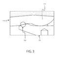
- FIG. 3 depicts a detailed view of the nozzle assembly of FIG. 1 .
- FIG. 4 depicts an embodiment of a system for debris removal.
- FIG. 5 depicts an embodiment of the system of FIG. 4 located in a well.
- FIG. 6 depicts an example of a flow path generated in the well of FIG. 5 during debris removal operations.
- FIG. 7 depicts an embodiment of a method for debris removal in a well.
- An example nozzle assembly includes a nozzle.
- the nozzle can have an elongated body.
- the elongated body can have a nozzle end at one end and a connection portion at another end.
- the connection portion can be a ball, a linkage, or other joint connection.
- the nozzle assembly can also include a joint section.
- the joint section connects with the connection portion.
- the joint section allows the nozzle to move axially and radially when an axial force is applied to the nozzle end.
- the joint section and the connection can form a ball joint, and a wedge contact on the joint section can cause the nozzle to move radially and axially as an axial force is applied to the nozzle end.
- the joint section and connection portion can connect in any manner that allows the nozzle to move radially and axially when an axial force is applied to the nozzle.
- the joint section can have any configuration that is configured to connect with the connection portion.
- the joint section and connection portion can be a pair of links, a ball joint, or the like.
- the nozzle assembly can be connected with a suction tool to form a system for collecting debris.
- the suction tool can be configured to connect with a wireline, a slickline, a tool string, a tubular string, or other well conveyance device.
- FIG. 1 depicts an embodiment of a nozzle assembly.
- FIG. 2 depicts the nozzle assembly of FIG. 1 with a nozzle moved axially and radially.
- FIG. 3 depicts a detailed view of the nozzle assembly of FIG. 1 .
- the nozzle assembly 100 can include a nozzle 110 and a joint section 120 .
- the nozzle 110 has an elongated body 112 .
- the elongated body 112 has a nozzle end 116 and a connection portion 114 .
- the nozzle 110 can have a flow path 118 formed therethrough.
- the joint section 120 connects with the connection portion 114 .
- the joint section 120 and connection portion 114 can form a ball joint.
- the joint section 120 can be configured to allow the nozzle 110 to move axially when an axial force is applied to the nozzle end 116 .
- the axial force can be applied by an obstruction in the well.
- the joint section 120 is configured to transfer a portion of the axial force to a radial force, causing the nozzle 110 to move radially.
- a wedge contact 122 can transfer some of the axial force to a centering force, causing radial motion to be imparted to the nozzle 110 .
- the geometry of the wedge contact 122 can have a geometry that provides a mechanical advantage sufficient to make the centering force greater than the opposing friction generated by the axial force and the obstruction.
- FIG. 4 depicts an embodiment of a system for debris removal.
- the system 400 includes a suction tool 410 with the nozzle assembly 100 connected therewith.
- the suction tool 410 includes a debris storage section 412 , a pump section 414 , and a power section 416 .
- the suction tool 410 can also include ports 418 .
- FIG. 5 depicts an embodiment of the system of FIG. 4 located in a well.
- the system 400 can be connected with a wireline 512 .
- the wireline 512 is operatively connected with a winch 514 and a control unit 516 .
- a derrick 510 supports the wireline 512 .
- the wireline 512 is used to move the system 400 into the well 500 .
- the well 500 can have a vertical section 502 and a deviated section 504 .
- the system 400 can be moved within the well 500 .
- the system 400 can be poisoned in the deviated section 504 to perform a debris removal operation, and the nozzle assembly 100 allows the nozzle end to be oriented in a proper position relative to the well 500 .
- FIG. 6 depicts an example of a flow path generated in the well of FIG. 5 during debris removal operations.
- An annulus 600 can be formed between the system 400 and the well 500 .
- fluid 610 is discharged from ports 418 .
- the fluid 610 traverses the annulus 600 and collects debris in the annulus 600 .
- the fluid 610 and collected debris are drawn through the nozzle assembly 100 to the debris storage section 410 .
- the debris storage section 410 removes the debris from the fluid 610 , and the fluid 610 can then be circulated back to the annulus to collect additional debris.
- FIG. 7 depicts an embodiment of a method for debris removal in a well.
- the method 700 is depicted as a plurality of blocks or operations.
- the method 700 includes moving a system for collecting debris in a well (block 710 ).
- the system for collecting debris includes a nozzle assembly connected with a suction tool, and the nozzle assembly includes a nozzle.
- the method also includes moving the nozzle radially and axially when axial force from an obstruction is applied to a portion of the nozzle (block 712 ).
- the method can also include positioning the system for collecting debris at a desired location in the well and at a desired orientation (block 714 ).
- the desired orientation can be any relationship with the well required to perform a desired operation.
- the desired orientation can be such that a suction port for a debris collection tool is allowed to be located along the low side of completion tubular or well.
- the method can also include performing a debris removal operation (block 716 ).
Abstract
A nozzle assembly including a nozzle. The nozzle has an elongated body. The elongated body has a nozzle end at one end and a connection portion at another end. A joint section is connected with the connection portion. The joint section allows the nozzle to move axially and radially when an axial force is applied to the nozzle end.
Description
This Application is a continuation of co-pending U.S. patent application Ser. No. 14/029,692, which was filed on Oct. 27, 2015, entitled Nozzle Assembly. The foregoing application is incorporated herein by reference.
The disclosure generally relates to a nozzle assembly and systems and methods for debris collection that utilize the nozzle assembly.
Tools used in wells often have a component that is located along a low side of a well. For example, debris removal devices need to have a suction port or nozzle inlet located at the low side of a well. Obstructions in a well make conveyance of tools having components located at the low side of the well difficult. To aid in the conveyance bullnoses are used to push the tool towards the center of the well. Bullnoses, however, can be cumbersome and add size and weight to the tool as well as impede the orientation functionality required. A need, therefore, exists for a nozzle assembly that functions similar to a bullnose without the restrictions imposed by conventional bullnose designs.
An embodiment of a nozzle assembly can include a nozzle. The nozzle can have an elongated body. The elongated body can have a nozzle end located at one end and a connection portion located at another end. The connection portion can be connected with a joint section. The joint section can allow the nozzle to move axially and radially when an axial force is applied to the nozzle end.
An embodiment of a system for collecting debris can include the nozzle assembly connected with a suction tool.
An embodiment of a method for debris removal in a well can include moving a system for debris removal in a well and moving the nozzle radially and axially when axial force from an obstruction is applied to a portion of the nozzle. The method can also include positioning the suction tool at a desired location in the well and performing a debris removal operation.
Certain examples are shown in the above-identified figures and described in detail below. In describing these examples, like or identical reference numbers are used to identify common or similar elements. The figures are not necessarily to scale and certain features and certain views of the figures may be shown exaggerated in scale or in schematic for clarity and/or conciseness.
An example nozzle assembly includes a nozzle. The nozzle can have an elongated body. The elongated body can have a nozzle end at one end and a connection portion at another end. The connection portion can be a ball, a linkage, or other joint connection.
The nozzle assembly can also include a joint section. The joint section connects with the connection portion. The joint section allows the nozzle to move axially and radially when an axial force is applied to the nozzle end. For example, the joint section and the connection can form a ball joint, and a wedge contact on the joint section can cause the nozzle to move radially and axially as an axial force is applied to the nozzle end. The joint section and connection portion can connect in any manner that allows the nozzle to move radially and axially when an axial force is applied to the nozzle. The joint section can have any configuration that is configured to connect with the connection portion. The joint section and connection portion can be a pair of links, a ball joint, or the like.
The nozzle assembly can be connected with a suction tool to form a system for collecting debris. The suction tool can be configured to connect with a wireline, a slickline, a tool string, a tubular string, or other well conveyance device.
Turning now to the Figures. FIG. 1 depicts an embodiment of a nozzle assembly. FIG. 2 depicts the nozzle assembly of FIG. 1 with a nozzle moved axially and radially. FIG. 3 depicts a detailed view of the nozzle assembly of FIG. 1 .
Referring now to FIGS. 1 to 3 , the nozzle assembly 100 can include a nozzle 110 and a joint section 120.
The nozzle 110 has an elongated body 112. The elongated body 112 has a nozzle end 116 and a connection portion 114. The nozzle 110 can have a flow path 118 formed therethrough.
The joint section 120 connects with the connection portion 114. For example, as depicted in FIGS. 1 to 3 , the joint section 120 and connection portion 114 can form a ball joint. The joint section 120 can be configured to allow the nozzle 110 to move axially when an axial force is applied to the nozzle end 116. The axial force can be applied by an obstruction in the well. In addition, the joint section 120 is configured to transfer a portion of the axial force to a radial force, causing the nozzle 110 to move radially. For example, as shown in FIGS. 1 to 3 , a wedge contact 122 can transfer some of the axial force to a centering force, causing radial motion to be imparted to the nozzle 110. The geometry of the wedge contact 122 can have a geometry that provides a mechanical advantage sufficient to make the centering force greater than the opposing friction generated by the axial force and the obstruction. One skilled in the art, with the aid of this disclosure, would be able to calculate the geometry of the contact portion without undue experimentation.
The system 400 can be connected with a wireline 512. The wireline 512 is operatively connected with a winch 514 and a control unit 516. A derrick 510 supports the wireline 512. The wireline 512 is used to move the system 400 into the well 500. The well 500 can have a vertical section 502 and a deviated section 504. The system 400 can be moved within the well 500. The system 400 can be poisoned in the deviated section 504 to perform a debris removal operation, and the nozzle assembly 100 allows the nozzle end to be oriented in a proper position relative to the well 500.
The method 700 is depicted as a plurality of blocks or operations. The method 700 includes moving a system for collecting debris in a well (block 710). The system for collecting debris includes a nozzle assembly connected with a suction tool, and the nozzle assembly includes a nozzle.
The method also includes moving the nozzle radially and axially when axial force from an obstruction is applied to a portion of the nozzle (block 712). The method can also include positioning the system for collecting debris at a desired location in the well and at a desired orientation (block 714). The desired orientation can be any relationship with the well required to perform a desired operation. For example, the desired orientation can be such that a suction port for a debris collection tool is allowed to be located along the low side of completion tubular or well. The method can also include performing a debris removal operation (block 716).
Although example assemblies, methods, systems have been described herein, the scope of coverage of this patent is not limited thereto. On the contrary, this patent covers every method, nozzle assembly, and article of manufacture fairly falling within the scope of the appended claims either literally or under the doctrine of equivalents.
Claims (7)
1. A system for collecting debris, wherein the system is used in a well, and wherein the system comprises:
a nozzle assembly comprising:
a nozzle comprising:
an elongated body;
a nozzle end located on one end of the elongated body; and
a connection portion located at another end of the elongated body; and
a joint section connected with the connection portion, wherein the joint section allows the nozzle to move axially and radially when an axial force is applied to the nozzle end; and
a suction tool connected with the joint section.
2. The system of claim 1 , wherein the connection portion is a ball.
3. A method for debris removal in a well, wherein the method comprises:
moving a system for collecting debris in a well, wherein the system for collecting debris comprises a nozzle assembly, wherein the nozzle assembly comprises a nozzle;
moving the nozzle radially and axially when axial force from an obstruction is applied to a portion of the nozzle; and
positioning the system for collecting debris at a desired location in the well and performing a debris removal operation.
4. The method of claim 3 , wherein the nozzle comprises:
an elongated body;
a nozzle end located on one end of the elongated body; and
a connection portion located at another end of the elongated body.
5. The method of claim 4 , wherein a joint section is connected with the connection portion, wherein the joint section allows the nozzle to move axially and radially when an axial force is applied to the nozzle end.
6. The method of claim 5 , wherein the joint section is connected with a suction tool.
7. The method of claim 5 , wherein the joint section comprises:
a wedge contact to provide radial motion to the nozzle when the axial force is applied to the nozzle end.
Priority Applications (1)
| Application Number | Priority Date | Filing Date | Title |
|---|---|---|---|
| US14/922,901 US9500065B2 (en) | 2013-09-17 | 2015-10-26 | Nozzle assembly |
Applications Claiming Priority (2)
| Application Number | Priority Date | Filing Date | Title |
|---|---|---|---|
| US14/029,692 US9169718B2 (en) | 2013-09-17 | 2013-09-17 | Nozzle assembly |
| US14/922,901 US9500065B2 (en) | 2013-09-17 | 2015-10-26 | Nozzle assembly |
Related Parent Applications (1)
| Application Number | Title | Priority Date | Filing Date |
|---|---|---|---|
| US14/029,692 Continuation US9169718B2 (en) | 2013-09-17 | 2013-09-17 | Nozzle assembly |
Publications (2)
| Publication Number | Publication Date |
|---|---|
| US20160047202A1 US20160047202A1 (en) | 2016-02-18 |
| US9500065B2 true US9500065B2 (en) | 2016-11-22 |
Family
ID=52666914
Family Applications (2)
| Application Number | Title | Priority Date | Filing Date |
|---|---|---|---|
| US14/029,692 Active 2034-01-19 US9169718B2 (en) | 2013-09-17 | 2013-09-17 | Nozzle assembly |
| US14/922,901 Expired - Fee Related US9500065B2 (en) | 2013-09-17 | 2015-10-26 | Nozzle assembly |
Family Applications Before (1)
| Application Number | Title | Priority Date | Filing Date |
|---|---|---|---|
| US14/029,692 Active 2034-01-19 US9169718B2 (en) | 2013-09-17 | 2013-09-17 | Nozzle assembly |
Country Status (2)
| Country | Link |
|---|---|
| US (2) | US9169718B2 (en) |
| WO (1) | WO2015041933A1 (en) |
Families Citing this family (2)
| Publication number | Priority date | Publication date | Assignee | Title |
|---|---|---|---|---|
| US9169718B2 (en) | 2013-09-17 | 2015-10-27 | Schlumberger Technology Corporation | Nozzle assembly |
| CN110630201B (en) * | 2018-06-22 | 2022-02-01 | 中国石油天然气股份有限公司 | Snake-shaped guide ejector |
Citations (9)
| Publication number | Priority date | Publication date | Assignee | Title |
|---|---|---|---|---|
| US2263850A (en) * | 1940-01-30 | 1941-11-25 | Aro Equipment Corp | Hydraulic coupler for grease fittings |
| US4040650A (en) | 1975-01-07 | 1977-08-09 | Comex Marine Services, Inc. | Articulate conduit connector |
| US4045054A (en) | 1972-09-28 | 1977-08-30 | Hydrotech International, Inc. | Apparatus for rigidly interconnecting misaligned pipe ends |
| US4180285A (en) | 1978-05-11 | 1979-12-25 | Reneau Bobby J | Articulated ball connector for use with pipeline |
| US6640897B1 (en) | 1999-09-10 | 2003-11-04 | Bj Services Company | Method and apparatus for through tubing gravel packing, cleaning and lifting |
| US20100243258A1 (en) | 2009-03-26 | 2010-09-30 | Smith International, Inc. | Debris catcher for collecting well debris |
| US7878247B2 (en) | 2009-01-08 | 2011-02-01 | Baker Hughes Incorporated | Methods for cleaning out horizontal wellbores using coiled tubing |
| US20120048569A1 (en) | 2003-09-10 | 2012-03-01 | Williams Danny T | Downhole Draw-Down Pump and Method |
| US9169718B2 (en) | 2013-09-17 | 2015-10-27 | Schlumberger Technology Corporation | Nozzle assembly |
-
2013
- 2013-09-17 US US14/029,692 patent/US9169718B2/en active Active
-
2014
- 2014-09-12 WO PCT/US2014/055300 patent/WO2015041933A1/en active Application Filing
-
2015
- 2015-10-26 US US14/922,901 patent/US9500065B2/en not_active Expired - Fee Related
Patent Citations (9)
| Publication number | Priority date | Publication date | Assignee | Title |
|---|---|---|---|---|
| US2263850A (en) * | 1940-01-30 | 1941-11-25 | Aro Equipment Corp | Hydraulic coupler for grease fittings |
| US4045054A (en) | 1972-09-28 | 1977-08-30 | Hydrotech International, Inc. | Apparatus for rigidly interconnecting misaligned pipe ends |
| US4040650A (en) | 1975-01-07 | 1977-08-09 | Comex Marine Services, Inc. | Articulate conduit connector |
| US4180285A (en) | 1978-05-11 | 1979-12-25 | Reneau Bobby J | Articulated ball connector for use with pipeline |
| US6640897B1 (en) | 1999-09-10 | 2003-11-04 | Bj Services Company | Method and apparatus for through tubing gravel packing, cleaning and lifting |
| US20120048569A1 (en) | 2003-09-10 | 2012-03-01 | Williams Danny T | Downhole Draw-Down Pump and Method |
| US7878247B2 (en) | 2009-01-08 | 2011-02-01 | Baker Hughes Incorporated | Methods for cleaning out horizontal wellbores using coiled tubing |
| US20100243258A1 (en) | 2009-03-26 | 2010-09-30 | Smith International, Inc. | Debris catcher for collecting well debris |
| US9169718B2 (en) | 2013-09-17 | 2015-10-27 | Schlumberger Technology Corporation | Nozzle assembly |
Non-Patent Citations (1)
| Title |
|---|
| International Search Report and the Written Opinion for International Application No. PCT/US2014/055300 dated Dec. 22, 2014. |
Also Published As
| Publication number | Publication date |
|---|---|
| US20160047202A1 (en) | 2016-02-18 |
| US9169718B2 (en) | 2015-10-27 |
| US20150075794A1 (en) | 2015-03-19 |
| WO2015041933A1 (en) | 2015-03-26 |
Similar Documents
| Publication | Publication Date | Title |
|---|---|---|
| EP3152390B1 (en) | Apparatus, system, and methods for downhole debris collection | |
| US8240373B1 (en) | Apparatus and method for removing debris from a well | |
| US20160319619A1 (en) | Extended duration section mill and methods of use | |
| US8220555B1 (en) | Downhole tool shifting mechanism and method for shifting a downhole tool | |
| US20150176361A1 (en) | Downhole tool with expandable annular plug seat assembly having circumferentially overlapping seat segment joints | |
| US9500065B2 (en) | Nozzle assembly | |
| US9267331B2 (en) | Expandable reamers and methods of using expandable reamers | |
| US20120186823A1 (en) | Expanding mill having camming sleeve for extending cutting blade | |
| US8973662B2 (en) | Downhole debris removal tool capable of providing a hydraulic barrier and methods of using same | |
| EP3047093B1 (en) | Variable diameter bullnose assembly | |
| NO347795B1 (en) | Self-boosting expandable seal with cantilevered seal arm | |
| CN110382813A (en) | Method and apparatus for reducing the loss of the underground in drill-well operation, preventing bit freezing and hole from cleaning enhancing | |
| CN112969840B (en) | Disturbance-based borehole diameter reconstruction | |
| RU2655074C2 (en) | Downhole apparatus and method | |
| CN105378208A (en) | Expandadle bullnose assembly for use with a wellbore deflector | |
| US20210207448A1 (en) | Apparatus for Downhole Milling of Material of a Well Wall | |
| US7979944B1 (en) | Tubular cleaning device | |
| US10648290B2 (en) | Sleeve shifting tool | |
| EP3423665B1 (en) | A continuous wedging tool for directional diamond drilling | |
| CA3025293C (en) | Expandable junk mill | |
| US10151163B2 (en) | Expandable junk mill stabilizer | |
| US20150083437A1 (en) | Method And Apparatus To Enable Toolstring To Negotiate Obstructions Downhole | |
| CA2998378C (en) | Downhole seal | |
| US10794133B2 (en) | Conveyance member for a resource exploration and recovery system | |
| US10107066B2 (en) | Anti-creep rings and configurations for single packers |
Legal Events
| Date | Code | Title | Description |
|---|---|---|---|
| STCF | Information on status: patent grant |
Free format text: PATENTED CASE |
|
| FEPP | Fee payment procedure |
Free format text: MAINTENANCE FEE REMINDER MAILED (ORIGINAL EVENT CODE: REM.); ENTITY STATUS OF PATENT OWNER: LARGE ENTITY |
|
| LAPS | Lapse for failure to pay maintenance fees |
Free format text: PATENT EXPIRED FOR FAILURE TO PAY MAINTENANCE FEES (ORIGINAL EVENT CODE: EXP.); ENTITY STATUS OF PATENT OWNER: LARGE ENTITY |
|
| STCH | Information on status: patent discontinuation |
Free format text: PATENT EXPIRED DUE TO NONPAYMENT OF MAINTENANCE FEES UNDER 37 CFR 1.362 |
|
| FP | Lapsed due to failure to pay maintenance fee |
Effective date: 20201122 |