US949902A - Machine for the production of mosaic pictures. - Google Patents
Machine for the production of mosaic pictures. Download PDFInfo
- Publication number
- US949902A US949902A US36790507A US1907367905A US949902A US 949902 A US949902 A US 949902A US 36790507 A US36790507 A US 36790507A US 1907367905 A US1907367905 A US 1907367905A US 949902 A US949902 A US 949902A
- Authority
- US
- United States
- Prior art keywords
- machine
- production
- mosaic
- plates
- pictures
- Prior art date
- Legal status (The legal status is an assumption and is not a legal conclusion. Google has not performed a legal analysis and makes no representation as to the accuracy of the status listed.)
- Expired - Lifetime
Links
- 238000004519 manufacturing process Methods 0.000 title description 24
- OKTJSMMVPCPJKN-UHFFFAOYSA-N Carbon Chemical compound [C] OKTJSMMVPCPJKN-UHFFFAOYSA-N 0.000 description 9
- 239000003086 colorant Substances 0.000 description 8
- 230000033458 reproduction Effects 0.000 description 6
- 239000002184 metal Substances 0.000 description 5
- 239000011248 coating agent Substances 0.000 description 4
- 238000000576 coating method Methods 0.000 description 4
- 239000010426 asphalt Substances 0.000 description 3
- 230000033001 locomotion Effects 0.000 description 3
- 239000000463 material Substances 0.000 description 3
- 238000000034 method Methods 0.000 description 2
- 241000920033 Eugenes Species 0.000 description 1
- 235000008753 Papaver somniferum Nutrition 0.000 description 1
- 240000001090 Papaver somniferum Species 0.000 description 1
- 241000779819 Syncarpia glomulifera Species 0.000 description 1
- 230000005540 biological transmission Effects 0.000 description 1
- 230000015572 biosynthetic process Effects 0.000 description 1
- 239000004020 conductor Substances 0.000 description 1
- 238000006073 displacement reaction Methods 0.000 description 1
- 238000009432 framing Methods 0.000 description 1
- 229920000159 gelatin Polymers 0.000 description 1
- 239000008273 gelatin Substances 0.000 description 1
- 239000011521 glass Substances 0.000 description 1
- 239000007788 liquid Substances 0.000 description 1
- 230000009347 mechanical transmission Effects 0.000 description 1
- 239000000203 mixture Substances 0.000 description 1
- 230000004048 modification Effects 0.000 description 1
- 238000012986 modification Methods 0.000 description 1
- 239000001739 pinus spp. Substances 0.000 description 1
- 239000011347 resin Substances 0.000 description 1
- 229920005989 resin Polymers 0.000 description 1
- 230000000284 resting effect Effects 0.000 description 1
- 239000011343 solid material Substances 0.000 description 1
- 239000012780 transparent material Substances 0.000 description 1
- 229940036248 turpentine Drugs 0.000 description 1
Images


Classifications
-
- B—PERFORMING OPERATIONS; TRANSPORTING
- B29—WORKING OF PLASTICS; WORKING OF SUBSTANCES IN A PLASTIC STATE IN GENERAL
- B29C—SHAPING OR JOINING OF PLASTICS; SHAPING OF MATERIAL IN A PLASTIC STATE, NOT OTHERWISE PROVIDED FOR; AFTER-TREATMENT OF THE SHAPED PRODUCTS, e.g. REPAIRING
- B29C66/00—General aspects of processes or apparatus for joining preformed parts
- B29C66/80—General aspects of machine operations or constructions and parts thereof
-
- Y—GENERAL TAGGING OF NEW TECHNOLOGICAL DEVELOPMENTS; GENERAL TAGGING OF CROSS-SECTIONAL TECHNOLOGIES SPANNING OVER SEVERAL SECTIONS OF THE IPC; TECHNICAL SUBJECTS COVERED BY FORMER USPC CROSS-REFERENCE ART COLLECTIONS [XRACs] AND DIGESTS
- Y10—TECHNICAL SUBJECTS COVERED BY FORMER USPC
- Y10T—TECHNICAL SUBJECTS COVERED BY FORMER US CLASSIFICATION
- Y10T156/00—Adhesive bonding and miscellaneous chemical manufacture
- Y10T156/10—Methods of surface bonding and/or assembly therefor
- Y10T156/1089—Methods of surface bonding and/or assembly therefor of discrete laminae to single face of additional lamina
- Y10T156/1092—All laminae planar and face to face
-
- Y—GENERAL TAGGING OF NEW TECHNOLOGICAL DEVELOPMENTS; GENERAL TAGGING OF CROSS-SECTIONAL TECHNOLOGIES SPANNING OVER SEVERAL SECTIONS OF THE IPC; TECHNICAL SUBJECTS COVERED BY FORMER USPC CROSS-REFERENCE ART COLLECTIONS [XRACs] AND DIGESTS
- Y10—TECHNICAL SUBJECTS COVERED BY FORMER USPC
- Y10T—TECHNICAL SUBJECTS COVERED BY FORMER US CLASSIFICATION
- Y10T156/00—Adhesive bonding and miscellaneous chemical manufacture
- Y10T156/17—Surface bonding means and/or assemblymeans with work feeding or handling means
- Y10T156/1702—For plural parts or plural areas of single part
- Y10T156/1744—Means bringing discrete articles into assembled relationship
- Y10T156/1751—At least three articles
- Y10T156/1754—At least two applied side by side to common base
-
- Y—GENERAL TAGGING OF NEW TECHNOLOGICAL DEVELOPMENTS; GENERAL TAGGING OF CROSS-SECTIONAL TECHNOLOGIES SPANNING OVER SEVERAL SECTIONS OF THE IPC; TECHNICAL SUBJECTS COVERED BY FORMER USPC CROSS-REFERENCE ART COLLECTIONS [XRACs] AND DIGESTS
- Y10—TECHNICAL SUBJECTS COVERED BY FORMER USPC
- Y10T—TECHNICAL SUBJECTS COVERED BY FORMER US CLASSIFICATION
- Y10T29/00—Metal working
- Y10T29/23—Gem and jewel setting
-
- Y—GENERAL TAGGING OF NEW TECHNOLOGICAL DEVELOPMENTS; GENERAL TAGGING OF CROSS-SECTIONAL TECHNOLOGIES SPANNING OVER SEVERAL SECTIONS OF THE IPC; TECHNICAL SUBJECTS COVERED BY FORMER USPC CROSS-REFERENCE ART COLLECTIONS [XRACs] AND DIGESTS
- Y10—TECHNICAL SUBJECTS COVERED BY FORMER USPC
- Y10T—TECHNICAL SUBJECTS COVERED BY FORMER US CLASSIFICATION
- Y10T29/00—Metal working
- Y10T29/53—Means to assemble or disassemble
- Y10T29/53478—Means to assemble or disassemble with magazine supply
Definitions
- the present invention relates to a machine for producing mosaic pictures.
- the materials of which the mosaic picture is formed are transferred to a backing, in accordance with the design, and are fixed or held in position on the same until the entire mosaic picture is completed.
- the mosaic picture may be produced in one or several colors, and the pattern is divided into as many sections as there are colors, in order that material of the particular color may be supplied.
- the material used for the production of the mosaic may be either separate colored blocks (cubes, pyramids, balls) of suitable solid material.
- the separate elements fall on to a backing or foundation which may consist of a net wherein the pieces are held, or the backing may be a flat or curved plate coated with resin, poppy oil or other hardening medium to which plate the descending pieces or glass mass will adhere.
- the machine employed for carrying out this process consists of several groups of mechanism.
- the first chief group relates to a frame on which are arranged the color plates or sectional pictures, which may be advantageously prepared by means of photography, and together make up the picture to be reproduced.
- three of these plates are for the red, blue and yellow sectional pictures, a fourth plate being for the white parts of the picture.
- the whole of the colors when mixed together give black, while mixtures of two of the colors give green, orange and violet respectively.
- the several plates with their sectional pictures are electrically conductive. By means of solenoids mechanical transmission is effected from the plates to a controlling de- Specification of Letters Patent.
- This second principal group in the machine consists in the ordinary form of eight cube magazines, for as many difierent colors, namely, the three primary colors, red, blue and yellow, the four mixed colors, black, green, orange and violet, and white for filling up.
- These magazines are arranged on a setting device common to them all, under which is arranged the backing, for instance, the supporting net, into which the cubes are to be inserted.
- the net is mounted on a drum which, in accordance with the progress of the work, is set in longitudinal and rotary motion by means of rack and pinion gear, a definite relation in point of size being maintained by means of the same gear between the parts of the picture or design in accordance with the patterns.
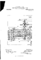
- Figures 1 and 1 constitute a plan view of a machine illustrating one embodiment of the invention.
- Figs. 2 and 2 constitute a side elevation thereof with parts in section.
- Fig. 3 is an end elevation, showing the setting device and driving mechanism.
- Fig. 4; is a longitudinal sectional view on the line A-B of Fig. 1.
- Fig. 5 represents, in plan, the first chief group in the machine, namely, the frame of the photographic color plates, in connection with the electrical and me chanical transmitting devices.
- Fig. 6 is a longitudinal section of Fig. 5.
- Fig. 7 is a view of the controlling device.
- Fig. 8 is a horizontal section of the same.
- Fig. 9 is a section through the setting device with the cube magazines on the line BC of Fig. 10.
- Fig. 10 is a section through the setting device with the cube magazines on the line BC of Fig. 10.
- Fig. 10 is a plan view of the setting device, the eccentric shaft being considered as taken away.
- Fig. 11 shows one of the cube magazines in partial section.
- Figs. 12 and 13 show a weighting block.
- Figs 14, 15 and 16 show the net drum with the net, in elevation, section and plan.
- Figs. 17 and 18 show one form of the mosaic blocks in bottom and side views respectively.
- Figs. 19 and 20 show the blocks set in the net.
- Fig. 21 shows a fastening strip for forming the net loop.
- Figs. 22, 23 and 24 represent details of the transmission gearing for the net drum.
- Figs. 25, 26 and 27 show the throwoff device for the belt on the pinion gearing in three aspects.
- Figs. 28 and 29 show the contact studs for the color plates.
- Fig. 30 shows the switch plan for the complete electrical circuit of the machine, and Figs. 31, 32, 83, and 34 are detached views of details of the machine.
- a framing device is provided for the plates 1, 2, 3 and 4:, provided with patterns, which device consists of a lower frame 5 supported on the table of the machine, and an upper frame 6 resting on the lower frame and forming the plate carrier.
- the two frames are connected to gether by means of bolts or screws 7
- the plates 14 which are furnished with the sectional pictures in separate colors-in the present hypothetical instance prepared by the three-color system of photographyare electrically conductive at their apportioned places in the total picture, so that the parts 8, 9, 10 for instance are non-conductive while the parts 11, 12, 13 on the other hand are conductive.
- the plates at, 3, 2 provided with the parts 8, 9, 10, correspond in the present instance to the primary colors, blue, yellow and red, while the plate 1, furnished with the conducting parts 11, 12, 13, serves the purpose of controlling the production of the white portions of the picture, i. 6., interrupts the formation of the picture at these parts.
- the plates are covered with a coating of asphaltum, chrome-gelatin or such like, said coating being adapted to react chemically under the influence of rays of light.
- Photographical reproductions of the pattern are made by means of red, yellow and blue light filters. Each of these reproductions (preferably made on transparent material) is placed upon one of said asphaltum or chromegelatin covered metal plates, which are then exposed to light. The reproductions are by these means transferred to the metal plate, which may afterward be developed in a similar way as any photographic plate.
- oil of turpentine is used. But it is obvious that any expert skilled in the art may use other developing liquids. Through the exposure of light the coating becomes insoluble on all those places, where it was not protected by the picture of the pattern.
- the coating is dissolved on all those places where it was covered with the reproduction, while it remains on all those places, which were not exposed to the action of the light.
- plates are obtained, which correspond with the reproduction obtained through the red filter, through the yellow filter and through the blue filter, respectively.
- the production of the picture from the said plates by means of suitable transmitting devices is effected automatically by a second main group in the machine.
- the said second chief part of the machine is provided with a magazine, which contains the mosaic blocks in separate compartments, according to color, 8 groups for example.
- the separate mosaic blocks from these groups are conveyed to the position on the said plates that they are to occupy in forming, the picture.
- This position corresponds with the part of the sectional plate at which contact has been made, and the transference is effected by electrically operated transport ing devices.
- These consist essentially of a controllin device which is charged with the task of efiecting the release of the mosaic blocks from the magazines in accordance with the displacement electrically imparted from the contact positions 011 the plates.
- the adjustment of the controlling device is efi'ected by means of solenoids which, in accordance with the modification represented, are employed in two groups. The former of these groups is coupled up in circuit with the plates and the source of current.
- the separate solenoids of this group then come into action as the circuit is completed by the contact with the conducting portions of the plate of the pins that slide over the plate.
- the plates which are made electrically conductive in the appropriate places, are connected with the circuit.
- the manner in which this is done is by making the upper frame part 6, which carries the plates 1, 2, 3, 4: of non-conducting material fitted with contacts 1d that grip the plates, these contacts being also connected with a source of current, a. g. a battery.
- Each of the cells is connected on the one hand with one of the plates 1, 2, 8, by the contact 141:, and on the other hand with one of the solenoids 16 of the first group by means of a contact device that can be moved over the plates.
- a separate contact device is provided for each of the plates, consisting essentially of metal pins 18 of a closed endless metal band 17, which pins slide over the full length of the plate when a longitudinal movement is imparted to the band.
- pins of this kind are mounted on each metal band 3 at intervals corresponding with the length of the plate. The longitudinal movement of the band is efi'ected by perforating the same all the way with holes 19 at suitable distances apart and by passing
Landscapes
- Engineering & Computer Science (AREA)
- Mechanical Engineering (AREA)
- Sampling And Sample Adjustment (AREA)
Description
E. KARAEEJ & A. REGAL. MACHINE FOR THE PRODUCTION OF MOSAIC PICTURES.
APPLICATION FILED APR. 12, 1907.
18 SHEETS-SHEET 1.
ANDREW B. QRARAM 00.. PMDTQLHMOGRAPHERS.WASHINGTON. 0.0
949,902. Patented Feb. 22, 1910.
E. KARAVZEJ & A. REGAL.
MACHINE FOR THE PRODUCTION OF MOSAIC PICTURES.
APPLICATION FILED APR. 12, 1907.
Patented Feb. 22, 1910.
18 SHBETS-SHBET 2.
ANRREW s GRANAHI co.. Pumoumocmwms, wAsumcToN. n. c
E. KARAZEJ & A MACHINE FOR THE PRODUCTION OF MOSAIC PICTURES.
. REGAL.
Patented Feb. 22; 1910.
APPLICATION FILED APR. 12, 1907. 949,902.
18 SHEETS-SHEET 3.
a mug E. KARAiEJ & A. REGAL.
MACHINE FOR THE PRODUCTION 01?v MOSAIC PICTURES.
APPLICATION FILED APR. 12, 1907. Patented Feb. 22, 1910.
18 SHEETS-SHEET 4.
flneizans'" E. KARAiBJ & A. REGAL.
MACHINE FOR THE PRODUCTION OF MOSAIC PICTURES.
APPLICATION FILED APR. 12, 1907. 902. Patented Feb. 22, 1910.
18 SHEETS-SHEET 5.
Fig.3.
m w m E. KARAfiEJ & A. REGAL.
MACHINE FOR THE PRODUCTION OF MOSAIC PICTURES.
, APPLICATION FILED APR. 12, 1907. 9%,902. Patented Feb. 22, 1910.
18 SHEETS-SHEET 6.
ANoRw a GEANAM Ix)- PWTO-LrIuOGRI-PNERS. WASWNGYOIQ D. c.
E. KARAEEJ & A. REGAL, MACHINE FOR THE PRODUCTION OF MOSAIC PICTURES.
. APPLIUATION FILED AFR.12, 1907. @QflQg Patented Feb. 22, 1919.
a 18 SHEETS-SHEET 7. ii
i s'@ W Fig.5.
fiomrzaor-sy- M712; 2 67 ANDREW B. GRAHAM ca. Pnoro-mnoaminms WASNINQYDN. n. c
E. KARAZEJ & A. REGAL,
MACHINE FOR THE PRODUCTION OF MOSAIC PIQTURES. APPLICATION FILED APR. 12, 1907.
949,909. Patented Feb.22,1910.
18 SHEETS-SHEET 8'.
E. KARALZEJ & A. REGAL.
MACHINE FOR THE PRODUCTION OF MOSAIC PIOTURBS. APPLICATION FILED APR.12, 1907.
18 SHEBTS-SHEET 9.
145 H .I 1 22 141 B. 131 127 m i 108 J 123 I, I I u n 1 I I l I 1 T 136 133 r 115 121 26 4 l 1 I 1 I I 1 3 M3 130 I 116 v 125 H, 103 45 l ,o- 0
7726,666668'; fitezzz oz zsz L zg/eizi zfizi azs 1.4 L M i Q ufij f Patented Feb. 22, 1910.
E. KARAZ EJ & A. REGAL. NE FOR THE PRODUCTION OF MOSAIC PIGT URES.
MAGHI APPLICATION FILED APR. 12, 1907.
Patented Feb. 22, 1910.
18 SHEETS-SHEET 10.
Fig.9
IagemJfZ; 7a; 279
ANDREW a saw: co Pnuwumusmwgns \LASHWGYON, u c
E. KARAiEJ & A. REGAL.
MACHINE FOR THE PRODUCTION OF MOSAIC PICTURES.
APPLIOATIOH FILED APR. 12, 1907. 949,902 Patented Feb. 22, 1910.
18 SHEETS-SHEET ll.
jmezztora E. KARAZ'EJ & A. REGAL. MACHINE FOR THE PRODUCTION OF MOSAIC PICTURES.
APPLICATION FILED APR. 12. 1907. 949,902.
Patented Feb. 22, 1910.
18 SHEETSSHEET l2v \ML .41 4 i i: 36 v a 36 L U 1 3 i Ly p77 fla /6 st 56 665 dZazvwy ANDREW u. GRA M cu woro-umocmwsns vmsumcww u (I E. KARAiEJ & A= REGAL. MACHINE FOR THE PRODUCTION OF MOSAIC PICTURES.
APPLICATION FILED APR. 12, 1907.
Patented Feb.22, 1910.
18 SHEETSSHEET 13.
ANDREW a. GRAHAM c0- Fumo-urnOGMPuERs. wAsumnmN. o. c
E. KARAZJEJ & A. REGAL.
MACHINE FOR THE- PRODUCTION OF MOSAIC PICTURES.-
APPLIOATION FILED APR. 12, 1907.
949,909, Patented Feb. 22, 1910.
18 SHEETS-SHEET 14.
Fig.2&
ANDREW a. GRANAM cow PHOYO-LH'NOGRAPNERS. wnsmucmw. n. a
B. KARAZ EJ & A. REGAL. MACHINE FOR THE PRODUOTIQN 0F MOSAIG PICTURES.
APPLICATION FILED APR. 12, 1907. 949,902, Patented Feb. 22, 1910.
18 SHEETS-SHEET 15.
E. KARAEEJ & A. REGAL. MACHINE FOR THE PRODUCTION OF MOSAIC PICTURES.
APPLICATION FILED APR.12, 1907.
Patented Feb. 22, 1910.
18 SHEETS-SHEET 16.
ANDREW a GRAHAM ca. Pnormumacnnlmzm WASNINGTON, n c,
E. KARAEEJ & A. REGAL.
MACHINE FOR THE PRODUCTION OF MOSAIQ PICTURES. APPLIOATION FILED APR. 12, 1907.
949,902. v Patented Feb. 22, 1910. 1a SHEETS-SHEET 17.
E. KARAiEJ & A. REGAL. MACHINE FOR THE PRODUCTION OF MOSAIC PICTURES.
APPLICATION IILBD APR. 12, 1907.
Patented Feb. 22, 1910.
18 SHEETS-SHEET 18.
Fig.33.
mmaaelsx- ATS ' tic.
MACHINE FOR THE PRODUCTION OF MOSAIC PICTURES.
To all whom it may concern:
Be it known that we, EUGEN K ARAzEJ and AUcUsr REGAL, subjects of the Emperorof Austria-Hungary, and residing in Banjaluka, Bosnia, Austria-Hungary, have invented a new or Improved Machine for the Production of Mosaic Pictures; and we do hereby declare the following to be a full, clear, and exact description of the invention, such as will enable others skilled in the art to which it appertains to make and use the same, reference being had to the accompanying drawings, and to characters of reference marked thereon, which form a part of this specification.
The present invention relates to a machine for producing mosaic pictures.
According to this invention the materials of which the mosaic picture is formed are transferred to a backing, in accordance with the design, and are fixed or held in position on the same until the entire mosaic picture is completed. The mosaic picture may be produced in one or several colors, and the pattern is divided into as many sections as there are colors, in order that material of the particular color may be supplied.
The material used for the production of the mosaic may be either separate colored blocks (cubes, pyramids, balls) of suitable solid material. The separate elements fall on to a backing or foundation which may consist of a net wherein the pieces are held, or the backing may be a flat or curved plate coated with resin, poppy oil or other hardening medium to which plate the descending pieces or glass mass will adhere.
The machine employed for carrying out this process consists of several groups of mechanism. The first chief group relates to a frame on which are arranged the color plates or sectional pictures, which may be advantageously prepared by means of photography, and together make up the picture to be reproduced. In the form of the machine illustrated in the drawings, three of these plates are for the red, blue and yellow sectional pictures, a fourth plate being for the white parts of the picture. The whole of the colors when mixed together give black, while mixtures of two of the colors give green, orange and violet respectively. The several plates with their sectional pictures are electrically conductive. By means of solenoids mechanical transmission is effected from the plates to a controlling de- Specification of Letters Patent.
Application filed April 12, 1907.
Patented Feb. 22, 1910.
Serial No. 367,905.
vice, which is connected with the device effecting the actual setting of the elements of the picture, hereinafter assumed, for the sake of example, to consist of mosaic blocks. This second principal group in the machine consists in the ordinary form of eight cube magazines, for as many difierent colors, namely, the three primary colors, red, blue and yellow, the four mixed colors, black, green, orange and violet, and white for filling up. These magazines are arranged on a setting device common to them all, under which is arranged the backing, for instance, the supporting net, into which the cubes are to be inserted. The net is mounted on a drum which, in accordance with the progress of the work, is set in longitudinal and rotary motion by means of rack and pinion gear, a definite relation in point of size being maintained by means of the same gear between the parts of the picture or design in accordance with the patterns.
The type of machine in question will now be described with reference to the accompanying drawings.
Figures 1 and 1 constitute a plan view of a machine illustrating one embodiment of the invention. Figs. 2 and 2 constitute a side elevation thereof with parts in section. Fig. 3 is an end elevation, showing the setting device and driving mechanism. Fig. 4; is a longitudinal sectional view on the line A-B of Fig. 1. Fig. 5 represents, in plan, the first chief group in the machine, namely, the frame of the photographic color plates, in connection with the electrical and me chanical transmitting devices. Fig. 6 is a longitudinal section of Fig. 5. Fig. 7 is a view of the controlling device. Fig. 8 is a horizontal section of the same. Fig. 9 is a section through the setting device with the cube magazines on the line BC of Fig. 10. Fig. 10 is a plan view of the setting device, the eccentric shaft being considered as taken away. Fig. 11 shows one of the cube magazines in partial section. Figs. 12 and 13 show a weighting block. Figs 14, 15 and 16 show the net drum with the net, in elevation, section and plan. Figs. 17 and 18 show one form of the mosaic blocks in bottom and side views respectively. Figs. 19 and 20 show the blocks set in the net. Fig. 21 shows a fastening strip for forming the net loop. Figs. 22, 23 and 24 represent details of the transmission gearing for the net drum. Figs. 25, 26 and 27 show the throwoff device for the belt on the pinion gearing in three aspects. Figs. 28 and 29 show the contact studs for the color plates. Fig. 30 shows the switch plan for the complete electrical circuit of the machine, and Figs. 31, 32, 83, and 34 are detached views of details of the machine.
First referring to the main group of parts (Figs. 5 and 6) a framing device is provided for the plates 1, 2, 3 and 4:, provided with patterns, which device consists of a lower frame 5 supported on the table of the machine, and an upper frame 6 resting on the lower frame and forming the plate carrier. The two frames are connected to gether by means of bolts or screws 7 The plates 14 which are furnished with the sectional pictures in separate colors-in the present hypothetical instance prepared by the three-color system of photographyare electrically conductive at their apportioned places in the total picture, so that the parts 8, 9, 10 for instance are non-conductive while the parts 11, 12, 13 on the other hand are conductive. The plates at, 3, 2 provided with the parts 8, 9, 10, correspond in the present instance to the primary colors, blue, yellow and red, while the plate 1, furnished with the conducting parts 11, 12, 13, serves the purpose of controlling the production of the white portions of the picture, i. 6., interrupts the formation of the picture at these parts.
There are various ways for manufacturing the plates, mentioned above. In the following (by way of example) one manufacturing method will be described.
The plates are covered with a coating of asphaltum, chrome-gelatin or such like, said coating being adapted to react chemically under the influence of rays of light. Photographical reproductions of the pattern are made by means of red, yellow and blue light filters. Each of these reproductions (preferably made on transparent material) is placed upon one of said asphaltum or chromegelatin covered metal plates, which are then exposed to light. The reproductions are by these means transferred to the metal plate, which may afterward be developed in a similar way as any photographic plate. To develop asphaltum reproductions, oil of turpentine is used. But it is obvious that any expert skilled in the art may use other developing liquids. Through the exposure of light the coating becomes insoluble on all those places, where it was not protected by the picture of the pattern. By the developing process the coating is dissolved on all those places where it was covered with the reproduction, while it remains on all those places, which were not exposed to the action of the light. By this means plates are obtained, which correspond with the reproduction obtained through the red filter, through the yellow filter and through the blue filter, respectively. As mentioned at the outset, the production of the picture from the said plates by means of suitable transmitting devices, is effected automatically by a second main group in the machine. In the present case in which the suitable setting of separately formed and colored mosaic blocks is the object to be attained, the said second chief part of the machine is provided with a magazine, which contains the mosaic blocks in separate compartments, according to color, 8 groups for example. In accordance with the manipulation of the contacts, the separate mosaic blocks from these groups are conveyed to the position on the said plates that they are to occupy in forming, the picture. This position corresponds with the part of the sectional plate at which contact has been made, and the transference is effected by electrically operated transport ing devices. These consist essentially of a controllin device which is charged with the task of efiecting the release of the mosaic blocks from the magazines in accordance with the displacement electrically imparted from the contact positions 011 the plates. As already mentioned, the adjustment of the controlling device is efi'ected by means of solenoids which, in accordance with the modification represented, are employed in two groups. The former of these groups is coupled up in circuit with the plates and the source of current. The separate solenoids of this group then come into action as the circuit is completed by the contact with the conducting portions of the plate of the pins that slide over the plate. For this purpose the plates, which are made electrically conductive in the appropriate places, are connected with the circuit. The manner in which this is done is by making the upper frame part 6, which carries the plates 1, 2, 3, 4: of non-conducting material fitted with contacts 1d that grip the plates, these contacts being also connected with a source of current, a. g. a battery. Each of the cells is connected on the one hand with one of the plates 1, 2, 8, by the contact 141:, and on the other hand with one of the solenoids 16 of the first group by means of a contact device that can be moved over the plates.
A separate contact device is provided for each of the plates, consisting essentially of metal pins 18 of a closed endless metal band 17, which pins slide over the full length of the plate when a longitudinal movement is imparted to the band. In order that at least one pin shall be at all times in contact with the plate, pins of this kind are mounted on each metal band 3 at intervals corresponding with the length of the plate. The longitudinal movement of the band is efi'ected by perforating the same all the way with holes 19 at suitable distances apart and by passing
Priority Applications (1)
| Application Number | Priority Date | Filing Date | Title |
|---|---|---|---|
| US36790507A US949902A (en) | 1907-04-12 | 1907-04-12 | Machine for the production of mosaic pictures. |
Applications Claiming Priority (1)
| Application Number | Priority Date | Filing Date | Title |
|---|---|---|---|
| US36790507A US949902A (en) | 1907-04-12 | 1907-04-12 | Machine for the production of mosaic pictures. |
Publications (1)
| Publication Number | Publication Date |
|---|---|
| US949902A true US949902A (en) | 1910-02-22 |
Family
ID=3018316
Family Applications (1)
| Application Number | Title | Priority Date | Filing Date |
|---|---|---|---|
| US36790507A Expired - Lifetime US949902A (en) | 1907-04-12 | 1907-04-12 | Machine for the production of mosaic pictures. |
Country Status (1)
| Country | Link |
|---|---|
| US (1) | US949902A (en) |
Cited By (2)
| Publication number | Priority date | Publication date | Assignee | Title |
|---|---|---|---|---|
| US2709864A (en) * | 1952-08-21 | 1955-06-07 | Stylon Corp | Machine for and method of assembling tile |
| US3118214A (en) * | 1959-10-08 | 1964-01-21 | Monarch Tool Co | Automatic ornament setting machine |
-
1907
- 1907-04-12 US US36790507A patent/US949902A/en not_active Expired - Lifetime
Cited By (2)
| Publication number | Priority date | Publication date | Assignee | Title |
|---|---|---|---|---|
| US2709864A (en) * | 1952-08-21 | 1955-06-07 | Stylon Corp | Machine for and method of assembling tile |
| US3118214A (en) * | 1959-10-08 | 1964-01-21 | Monarch Tool Co | Automatic ornament setting machine |
Similar Documents
| Publication | Publication Date | Title |
|---|---|---|
| FI813292A7 (en) | Photosensitive mixture, photosensitive impression material prepared therefrom, and method for producing a printing plate from the impression material. | |
| US949902A (en) | Machine for the production of mosaic pictures. | |
| JPS5652985A (en) | Preparation of transmission screen | |
| EP0472210A3 (en) | Production of color filter | |
| BE852585A (en) | PROCESS FOR MANUFACTURING THERMOPLASTIC POLYMERS WITH A BRANCHED CHAIN OF IMPROVED MECHANICAL STRENGTH IN THE MELT STATE | |
| GB1397814A (en) | Method of making a matrix for use in electroforming | |
| JPS51137733A (en) | Method to form a pattern coating with pictures or letters | |
| US727816A (en) | Screen or grating for half-tone photochemical engraving processes. | |
| US821200A (en) | Process for the production of photographs in natural colors. | |
| US178210A (en) | Improvement in the processes of producing photochromic prints | |
| US2958257A (en) | Method for the production of animated pictures | |
| JPS52149123A (en) | Color image forming method and apparatus | |
| US1872273A (en) | Transfer mechanism for production of printing plates | |
| US1735813A (en) | Multicolor cinematograph and other film and process of making same | |
| JPS52123823A (en) | Solid pickup element | |
| US1901110A (en) | Reversible mat | |
| US4529298A (en) | Step and repeat photo mask apparatus | |
| JPS6459354A (en) | Production of recessed part structure plate | |
| US874370A (en) | Process of weaving in natural colors without pattern-cards. | |
| GB191516201A (en) | Improvements in the Production and Exhibition of Colour Pictures, particularly Moving Pictures. | |
| JPS5778516A (en) | Production of printing pattern design | |
| US376247A (en) | le prince | |
| US695284A (en) | Method of making prismatic windows. | |
| GB1459228A (en) | Photocopying | |
| US926656A (en) | Pattern-plate for reproducing designs and the process of producing the same. |