US9497830B1 - Network-connected lighting structure with climate sensor, and related components, systems, and methods - Google Patents
Network-connected lighting structure with climate sensor, and related components, systems, and methods Download PDFInfo
- Publication number
- US9497830B1 US9497830B1 US14/812,203 US201514812203A US9497830B1 US 9497830 B1 US9497830 B1 US 9497830B1 US 201514812203 A US201514812203 A US 201514812203A US 9497830 B1 US9497830 B1 US 9497830B1
- Authority
- US
- United States
- Prior art keywords
- climate
- lighting structure
- controller
- ambient
- sensor
- Prior art date
- Legal status (The legal status is an assumption and is not a legal conclusion. Google has not performed a legal analysis and makes no representation as to the accuracy of the status listed.)
- Active
Links
- 238000000034 method Methods 0.000 title description 8
- 238000004891 communication Methods 0.000 claims abstract description 22
- 230000008859 change Effects 0.000 claims description 7
- 238000005286 illumination Methods 0.000 claims description 2
- 238000010586 diagram Methods 0.000 description 7
- 230000007613 environmental effect Effects 0.000 description 5
- 238000005259 measurement Methods 0.000 description 4
- 230000006870 function Effects 0.000 description 3
- 238000012545 processing Methods 0.000 description 3
- 230000000007 visual effect Effects 0.000 description 3
- 230000008901 benefit Effects 0.000 description 2
- 238000012986 modification Methods 0.000 description 2
- 230000004048 modification Effects 0.000 description 2
- 230000005855 radiation Effects 0.000 description 2
- 238000003491 array Methods 0.000 description 1
- 239000003086 colorant Substances 0.000 description 1
- 230000000295 complement effect Effects 0.000 description 1
- 230000000694 effects Effects 0.000 description 1
- 230000007246 mechanism Effects 0.000 description 1
- 238000012544 monitoring process Methods 0.000 description 1
- 230000002093 peripheral effect Effects 0.000 description 1
- 230000004044 response Effects 0.000 description 1
- 239000007787 solid Substances 0.000 description 1
- 238000012546 transfer Methods 0.000 description 1
Images


Classifications
-
- H05B37/0227—
-
- H—ELECTRICITY
- H05—ELECTRIC TECHNIQUES NOT OTHERWISE PROVIDED FOR
- H05B—ELECTRIC HEATING; ELECTRIC LIGHT SOURCES NOT OTHERWISE PROVIDED FOR; CIRCUIT ARRANGEMENTS FOR ELECTRIC LIGHT SOURCES, IN GENERAL
- H05B47/00—Circuit arrangements for operating light sources in general, i.e. where the type of light source is not relevant
- H05B47/10—Controlling the light source
- H05B47/175—Controlling the light source by remote control
- H05B47/19—Controlling the light source by remote control via wireless transmission
-
- H—ELECTRICITY
- H05—ELECTRIC TECHNIQUES NOT OTHERWISE PROVIDED FOR
- H05B—ELECTRIC HEATING; ELECTRIC LIGHT SOURCES NOT OTHERWISE PROVIDED FOR; CIRCUIT ARRANGEMENTS FOR ELECTRIC LIGHT SOURCES, IN GENERAL
- H05B47/00—Circuit arrangements for operating light sources in general, i.e. where the type of light source is not relevant
- H05B47/10—Controlling the light source
- H05B47/175—Controlling the light source by remote control
- H05B47/196—Controlling the light source by remote control characterised by user interface arrangements
- H05B47/1965—Controlling the light source by remote control characterised by user interface arrangements using handheld communication devices
-
- H—ELECTRICITY
- H05—ELECTRIC TECHNIQUES NOT OTHERWISE PROVIDED FOR
- H05B—ELECTRIC HEATING; ELECTRIC LIGHT SOURCES NOT OTHERWISE PROVIDED FOR; CIRCUIT ARRANGEMENTS FOR ELECTRIC LIGHT SOURCES, IN GENERAL
- H05B47/00—Circuit arrangements for operating light sources in general, i.e. where the type of light source is not relevant
- H05B47/10—Controlling the light source
- H05B47/175—Controlling the light source by remote control
- H05B47/198—Grouping of control procedures or address assignation to light sources
- H05B47/1985—Creation of lighting zones or scenes
Definitions
- This disclosure is related to a lighting structure, and more specifically to a network-connected lighting structure with a climate sensor, and related components, systems, and methods.
- IoT Internet of Things
- a network-connected thermostat may enable remote control and monitoring of temperature characteristics in a dwelling or other structure.
- this connectivity also permits additional functionality that may not be directly related to the device's primary functionality, or that may interact with the device's primary functionality in unexpected ways.
- a lighting structure having a climate sensor, and related components, systems, and methods.
- a lighting structure includes at least one light source and at least one climate sensor.
- Each climate sensor is configured to determine at least one ambient climate characteristic value that quantifies an ambient climate characteristic at a location distant from the lighting structure.
- an ambient climate characteristic may be an ambient temperature of an area such as a room, or of a distant object in the same room as the lighting structure.
- the lighting structure also includes a controller in communication with the at least one climate sensor. The controller is configured to receive the at least one ambient climate characteristic value from the at least one climate sensor.
- the controller may be further configured to transmit information based on the at least one ambient climate characteristic value to a network.
- the controller may be configured to affect the output of the light source in the structure based on the ambient climate characteristic.
- a lighting structure comprising at least one light source.
- the lighting structure also comprises at least one climate sensor.
- the at least one climate sensor is configured to determine at least one ambient climate characteristic value that quantifies an ambient climate characteristic at a location outside the lighting structure.
- the lighting structure further comprises a controller in communication with the at least one climate sensor.
- the controller is configured to receive the at least one ambient climate characteristic value from the at least one climate sensor.
- the controller is further configured to transmit information based on the at least one ambient climate characteristic value to a network.
- a network-connected lighting system comprising a system controller.
- the system further comprises a plurality of lighting structures in communication with the system controller via a network.
- Each lighting structure comprises at least one light source.
- Each lighting structure further comprises at least one climate sensor.
- the at least one climate sensor is configured to determine at least one ambient climate characteristic value that quantifies an ambient climate characteristic at a location outside the lighting structure.
- Each lighting structure further comprises a structure controller in communication with the at least one climate sensor.
- the structure controller is configured to receive the at least one ambient climate characteristic value from the at least one climate sensor.
- the structure controller is further configured to transmit information based on the at least one ambient climate characteristic value to the system controller via the network.
- FIG. 1 illustrates a schematic diagram of a network-connected lighting structure according to an embodiment
- FIG. 2 illustrates a schematic diagram of a network-connected lighting system for a multi-story structure employing the lighting structures of FIG. 1 according to an embodiment
- FIG. 3 illustrates a schematic diagram of a floor plan having an array of lighting structures of FIG. 1 according to an embodiment
- FIG. 4 illustrates a schematic diagram of a network-connected lighting structure according to an alternative embodiment
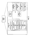
- FIG. 5 illustrates a block diagram of a network-connected lighting structure according to one embodiment.
- a lighting structure having a climate sensor, and related components, systems, and methods.
- a lighting structure includes at least one light source and at least one climate sensor.
- Each climate sensor is configured to determine at least one ambient climate characteristic value that quantifies an ambient climate characteristic at a location distant from the lighting structure.
- an ambient climate characteristic may be an ambient temperature of an area such as a room, or of a distant object in the same room as the lighting structure.
- the lighting structure also includes a controller in communication with the at least one climate sensor. The controller is configured to receive the at least one ambient climate characteristic value from the at least one climate sensor.
- the controller may be further configured to transmit information based on the at least one ambient climate characteristic value to a network.
- the controller may be configured to affect the output of the light source in the structure based on the ambient climate characteristic.
- a lighting structure may be a device which provides artificial light, such as by use of an electric light source.
- Such devices include lighting fixtures (also known as light fittings or luminaires) which have a body and at least one light socket to hold a removable electric light source such as a light bulb (sometimes referred to as a “lamp”) or light-emitting diode (LED).
- Lighting fixtures may be attached to a surface of a wall or ceiling, may be suspended, may be attached to a pole or other physical structure, may be recessed from a surface of a wall or ceiling, and may be attached to a track structure.
- Lighting fixtures may include structures that direct light, diffuse light, create pleasing visual effects, or a combination of these effects.
- Lighting structures also include lamps which may sit on a table or floor, are typically free-standing, have one or more light sockets, and may include one or more lampshade structures which diffuse or direct light from a light source.
- Light structures also include light panels, which are structures that contain one or more arrays of LEDs. The LEDs may be of a variety of types and colors which may be used alone or in combinations that allow a variety of visual effects to be created.
- Light structures also include light bulbs or other replaceable light sources or units that contain one or more LEDs or other light generation components.
- FIG. 1 illustrates a lighting structure 10 having a light source 12 and a climate sensor 14 .
- the climate sensor 14 is configured to determine at least one ambient climate characteristic value that quantifies an ambient climate characteristic 16 at a location outside the lighting structure 10 .
- the lighting structure 10 also includes a controller 20 in communication with the at least one climate sensor 14 .
- the controller 20 is configured to receive the at least one ambient climate characteristic value from the at least one climate sensor 14 .
- the controller 20 is also configured to determine information based on the at least one ambient climate characteristic value, and to transmit the information based on the at least one ambient climate characteristic value to a network 22 .
- the lighting structure 10 includes a light bulb 24 defining an interior space 26 .
- An LED element 28 or other type of light source is disposed inside the interior space 26 in this embodiment, and may also be in communication with the controller 20 .
- the light bulb 24 is installed in a fixture 30 , which may in turn be permanently installed in a known or knowable location on or inside a structure.
- the climate sensor 14 is a directional temperature sensor pointed at a distant object 18 within the line-of-sight of the climate sensor 14 .
- the climate sensor 14 is configured to detect infrared radiation corresponding to the climate characteristic 16 , i.e., the temperature at the distant object 18 location.
- climate sensors 14 may instead be configured to detect infrared radiation in a conical region corresponding to the climate characteristic in a defined area, such as an area intended to be inhabited or monitored, rather than a climate characteristic of an individual object 18 . It should also be understood that other types of climate sensors 14 may be used, such as a laser-based temperature sensor, an audio sensor, a video sensor, a still or a video camera, or other sensor that is capable of detecting a temperature or other climate characteristic at a location away from the lighting structure 10 .
- the climate characteristic 16 is a remote climate characteristic that is distant from the lighting structure 10 .
- This is in contrast to an immediate ambient climate characteristic of the area in the immediate vicinity of the lighting structure 10 .
- a temperature gauge that is configured to monitor an immediate ambient climate characteristic of the structure itself or in the immediate vicinity thereof would not be configured to also detect a remote ambient climate characteristic 16 at a location away from the lighting structure 10 because an ambient temperature of the lighting structure 10 may be significantly higher than the ambient temperature of a distant object 18 at a remote location away from the lighting structure 10 .
- the climate sensor 14 is connected to the controller by a wired sensor connection 32 , but it should be understood that the climate sensor 14 may alternatively use a wireless communication connection, such as a wireless transmitter, a receiver, and/or a transceiver in other embodiments.
- the controller 20 is connected to the network 22 via a wired network connection 34 , but it should also be understood that the climate sensor 14 may alternatively use a wireless communication connection in other embodiments.
- the climate sensor 14 is a stationary directional temperature sensor. It should be understood, however, that other types of climate sensors 14 may be used.
- the climate sensor 14 may have one or more adjustable parameters, such as direction, focus, intensity, or other parameters.
- the climate sensor 14 may have a first configuration configured to determine at least one ambient climate characteristic value that quantifies an ambient climate characteristic at a first location outside the lighting structure, and a second configuration configured to determine at least one ambient climate characteristic value that quantifies an ambient climate characteristic 16 at a second location outside the lighting structure.
- the parameters may be adjusted manually, remotely, or automatically in response to a determined parameter, for example, via the controller 20 .
- connection of the controller 20 to the network 22 may also provide for remote discovery, broadcast, provisioning, or reporting of the individual climate sensors 14 and their respective locations.
- the controller 20 may have connectivity to a building thermostat, such that the controller 20 can adjust local temperature settings based on a determined climate characteristic value from the climate sensor(s) 14 .
- the climate sensor 14 may be further configured to detect other climate characteristics 16 , such as a relative humidity or a barometric pressure, as an alternative to, or in addition to, the ambient temperature at a location outside the lighting structure 10 .
- the distant object 18 is illustrated as being located remotely from the lighting structure 10 .
- the distant object 18 may be located on a floor of a structure, or be part of a piece of furniture in the same room as the lighting structure.
- the climate sensor 14 is not configured to detect the climate characteristic 16 of the lighting structure 10 itself.
- an electrical structure such as the lighting structure 10 , may have an internal temperature significantly higher than the ambient climate characteristic 16 of the distant object 18 or the location being measured by the climate sensor 14 .
- using the climate sensor 14 configured to detect the climate characteristic 16 within or in close proximity to the lighting structure 10 may not be suitable for determining the ambient climate characteristic 16 of the distant object 18 or the location because the elevated temperature in and around the lighting structure 10 may not accurately reflect the actual ambient climate characteristics 16 within the overall space in which the lighting structure 10 is installed.
- FIG. 2 illustrates a diagram of a multi-story building 36 having a plurality of floors 38 ( 1 )- 38 ( 3 ).
- a plurality of lighting structures 10 ( 1 )- 10 (N) are distributed across the plurality of floors 38 ( 1 ) and 38 ( 2 ).
- Each lighting structure 10 ( 1 )- 10 (N) is in communication with a centralized system controller 40 , for example, via the respective controller 20 of each lighting structure 10 .
- each lighting structure 10 is in communication with the system controller 40 via a wired controller connection 42 .
- the system controller 40 is connected to a larger network 22 , such as the internet, via a communication channel 44 .
- each lighting structure 46 includes a wireless transceiver 48 ( 1 )- 48 (N) that communicates with a complementary wireless transceiver 50 in the system controller 40 .
- the system controller 40 is able to communicate with all of the lighting structures 10 ( 1 )- 10 (N), 46 ( 1 )- 46 (N) simultaneously, thereby allowing the system controller 40 to determine real time information with regard to climate characteristics 16 throughout the building 36 .
- This real time information can be used, for example, to control an HVAC system or to communicate the light source functionality of the lighting structures 10 , 46 to an installer or a technician.
- multiple systems or applications may use the determined climate characteristic value and/or information concurrently. For example, these systems or applications may be in communication with the system controller 40 , connected to the network 22 , or both.
- FIG. 3 illustrates an exemplary simplified floorplan of one of the plurality of floors 38 of the building 36 of FIG. 2 .
- the floor 38 includes a common area 52 in which a plurality of open cubicles 54 ( 1 )- 54 ( 6 ) are arranged.
- the floor 38 also includes a pair of closed offices 56 ( 1 ) and 56 ( 2 ).
- the lighting structures 10 are evenly distributed across the ceiling of the floor 38 in this embodiment. It can be seen that the lighting structures 10 may be positioned and distributed such that each area of interest includes at least one lighting structure 10 associated with it.
- each cubicle 54 and each office 56 has at least one lighting structure 10 positioned directly overhead.
- any number of climate characteristics 16 may be determined for a number of different specific locations within the floor 38 .
- one application of this arrangement can be to use the controllable LED functionality of the lighting structures 10 to create a “heat map” of the common area 52 that is readily visible to an installer or a technician inspecting the common area 52 .
- the lighting structures 10 within a sub-area 58 of the common area 52 may indicate that the ambient climate characteristics 16 such as the temperature are above a threshold level.
- Each controller 20 may be further configured to change the light source 12 (not shown) from a first state to a second state based on the at least one ambient climate characteristic value.
- individual controllers 20 of the lighting structures 10 and/or the system controller 40 may cause respective light sources 12 (not shown) of the lighting structures 10 to turn on or off, increase or decrease in brightness, change color and/or display various illumination patterns based on the determined climate characteristics 16 within the sub-area 58 .
- the lighting structures 10 within a second sub-area 60 of the common area 52 may determine that the determined climate characteristic values are below a threshold level, thereby causing the controller 20 and/or the system controller 40 to change the light sources 12 of the lighting structures 10 within the second sub-area 60 to a second lighting state different than a first lighting state, while the lighting structures 10 in a third sub-area 62 exhibit a third lighting state different from the first and second lighting state.
- a mobile device may be connected via the network 22 , and may be configured to communicate commands and receive information from one or more lighting structures 10 .
- FIG. 4 illustrates a lighting structure 10 ′ according to an alternative embodiment, in which a climate sensor 14 ′ is located inside a fixture 30 ′ of the lighting structure 10 ′.
- a light source 12 ′ is a “smart” light bulb 24 ′ disposed inside the interior space 26 ′ having a dedicated bulb controller 64 ′. It should be understood, however, that the light source 12 ′ may be a conventional light bulb in other embodiments.
- both the bulb controller 64 ′ and the climate sensor 14 ′ are in communication with a structure controller 66 ′, which is in turn in communication with network 22 ′.
- the climate sensor 14 ′ is connected to the structure controller 66 ′ via a wired sensor connection 68 ′.
- the bulb controller 64 ′ is also connected to the structure controller 66 ′ by a wired bulb connection 70 ′, and the structure controller 66 ′ is connected to the network 22 ′ by a wired network connection 72 ′ as well.
- wired connections 68 ′, 70 ′, and 72 ′ may be substituted with wireless connections as desired.
- FIG. 4 also shows additional climate sensor 74 ′ which may be the same or of a different type as climate sensor 14 ′.
- sensor 74 ′ is connected to the fixture controller 66 ′ via a wired sensor connection 76 ′, and may be similar to wired connection 68 ′.
- Sensor 74 ′ is positioned to make an environmental measurement of a distant object or area, which may be distant object 18 or may be another distant object or area (not shown). In this manner, multiple environmental sensors 14 ′, 74 ′ may be positioned within a single light structure 10 ′ to make environmental measurements of different distant objects or areas.
- FIG. 5 is a block diagram of a lighting structure 10 according to the embodiment of FIG. 1 . It should be understood, however, that the components of FIG. 5 may be used with other embodiments herein as well.
- the lighting structure 10 may comprise any computing or processing device capable of including firmware, hardware, and/or executing software instructions to implement the functionality described herein, and which is capable of being incorporated into components of the lighting structure 10 , including, for example, the light source 12 or the fixture 30 .
- the lighting structure 10 of FIG. 5 includes the controller 20 having a processor device 74 , a system memory 76 , and a system bus 78 .
- the system bus 78 provides an interface for system components including, but not limited to, the system memory 76 and the processor device 74 .
- the processor device 74 can be any commercially available or proprietary processor.
- the system bus 78 may be any of several types of bus structures that may further interconnect to a memory bus (with or without a memory controller), a peripheral bus, and/or a local bus using any of a variety of commercially available bus architectures.
- the system memory 76 may include non-volatile memory 80 (e.g., read only memory (ROM), erasable programmable read-only memory (EPROM), electrically erasable programmable read-only memory (EEPROM), etc., and/or volatile memory 82 (e.g., random-access memory (RAM).
- a basic input/output system (BIOS) 84 may be stored in the non-volatile memory 80 and can include the basic routines that help to transfer the information between the elements within the lighting structure 10 .
- the lighting structure 10 may further include a computer-readable storage device 86 , which may comprise, for example, internal solid state memory, or the like.
- the computer-readable storage device 86 may provide non-volatile storage of the data, the data structures, the computer-executable instructions, and the like.
- the data structures can store historical sensor readings which identify the sensor which made the measurement and a timestamp indicating the time the measurement was made.
- Computer-executable instructions may include pre-defined data processing instructions, or downloaded instructions for data processing at a specified time or interval.
- a number of modules can be stored in the computer-readable storage device 86 and/or in the volatile memory 82 , including an operating system 88 and one or more program modules 90 , which may implement the functionality described herein in whole or in part.
- the lighting structure 10 may include additional components, such as one or more climate sensors 14 , described in detail above, other types of sensors 92 , and a display 94 or other visual indicator interface.
- the components of the lighting structure 10 may interact with other components outside of the lighting structure 10 , such as a network 22 , via a communications interface 96 .
Landscapes
- Engineering & Computer Science (AREA)
- Computer Networks & Wireless Communication (AREA)
- Circuit Arrangement For Electric Light Sources In General (AREA)
Abstract
Description
Claims (22)
Priority Applications (1)
| Application Number | Priority Date | Filing Date | Title |
|---|---|---|---|
| US14/812,203 US9497830B1 (en) | 2015-07-29 | 2015-07-29 | Network-connected lighting structure with climate sensor, and related components, systems, and methods |
Applications Claiming Priority (1)
| Application Number | Priority Date | Filing Date | Title |
|---|---|---|---|
| US14/812,203 US9497830B1 (en) | 2015-07-29 | 2015-07-29 | Network-connected lighting structure with climate sensor, and related components, systems, and methods |
Publications (1)
| Publication Number | Publication Date |
|---|---|
| US9497830B1 true US9497830B1 (en) | 2016-11-15 |
Family
ID=57235214
Family Applications (1)
| Application Number | Title | Priority Date | Filing Date |
|---|---|---|---|
| US14/812,203 Active US9497830B1 (en) | 2015-07-29 | 2015-07-29 | Network-connected lighting structure with climate sensor, and related components, systems, and methods |
Country Status (1)
| Country | Link |
|---|---|
| US (1) | US9497830B1 (en) |
Cited By (2)
| Publication number | Priority date | Publication date | Assignee | Title |
|---|---|---|---|---|
| US11587322B2 (en) | 2016-12-09 | 2023-02-21 | Lutron Technology Company Llc | Load control system having a visible light sensor |
| US11843654B2 (en) | 2015-07-29 | 2023-12-12 | Avaya Inc. | Network-connected access point with environmental sensor, and related components, systems, and methods |
Citations (5)
| Publication number | Priority date | Publication date | Assignee | Title |
|---|---|---|---|---|
| US6697757B2 (en) * | 2001-09-19 | 2004-02-24 | Leviton Manufacturing Co., Ltd. | Local network based multiple sensor device with electrical load control means and with temperature sensor and heat detector that is exposed to ambient air by diffusion |
| US7499679B2 (en) | 2005-09-30 | 2009-03-03 | James Yang | Wireless network access point and sensor |
| US8610376B2 (en) | 2008-04-14 | 2013-12-17 | Digital Lumens Incorporated | LED lighting methods, apparatus, and systems including historic sensor data logging |
| US20140217927A1 (en) | 2012-12-31 | 2014-08-07 | Joseph Patrick Quinn | Temperature dependent hybrid light bulb |
| US8804622B1 (en) | 2011-12-30 | 2014-08-12 | Juniper Networks, Inc. | Wireless access points with modular attachments |
-
2015
- 2015-07-29 US US14/812,203 patent/US9497830B1/en active Active
Patent Citations (5)
| Publication number | Priority date | Publication date | Assignee | Title |
|---|---|---|---|---|
| US6697757B2 (en) * | 2001-09-19 | 2004-02-24 | Leviton Manufacturing Co., Ltd. | Local network based multiple sensor device with electrical load control means and with temperature sensor and heat detector that is exposed to ambient air by diffusion |
| US7499679B2 (en) | 2005-09-30 | 2009-03-03 | James Yang | Wireless network access point and sensor |
| US8610376B2 (en) | 2008-04-14 | 2013-12-17 | Digital Lumens Incorporated | LED lighting methods, apparatus, and systems including historic sensor data logging |
| US8804622B1 (en) | 2011-12-30 | 2014-08-12 | Juniper Networks, Inc. | Wireless access points with modular attachments |
| US20140217927A1 (en) | 2012-12-31 | 2014-08-07 | Joseph Patrick Quinn | Temperature dependent hybrid light bulb |
Cited By (7)
| Publication number | Priority date | Publication date | Assignee | Title |
|---|---|---|---|---|
| US11843654B2 (en) | 2015-07-29 | 2023-12-12 | Avaya Inc. | Network-connected access point with environmental sensor, and related components, systems, and methods |
| US11587322B2 (en) | 2016-12-09 | 2023-02-21 | Lutron Technology Company Llc | Load control system having a visible light sensor |
| US11600071B2 (en) | 2016-12-09 | 2023-03-07 | Lutron Technology Company Llc | Configuration of a visible light sensor |
| US11690152B2 (en) * | 2016-12-09 | 2023-06-27 | Lutron Technology Company Llc | Controlling lighting loads to achieve a desired lighting pattern |
| US11696382B2 (en) | 2016-12-09 | 2023-07-04 | Lutron Technology Company Llc | Measuring lighting levels using a visible light sensor |
| US11832365B2 (en) | 2016-12-09 | 2023-11-28 | Lutron Technology Company Llc | Load control system having a visible light sensor |
| US11979957B2 (en) | 2016-12-09 | 2024-05-07 | Lutron Technology Company Llc | Configuration of a visible light sensor |
Similar Documents
| Publication | Publication Date | Title |
|---|---|---|
| US10772171B2 (en) | Directional lighting system and method | |
| EP2745472B1 (en) | Commissioning of lighting systems | |
| US9198262B1 (en) | Directional lighting system and method | |
| US9370079B2 (en) | Methods and apparatus for automatically adapting light output of a lighting unit | |
| US11455884B2 (en) | Lighting system | |
| EP1932396B1 (en) | Method and device for grouping at least three lamps | |
| US8536505B2 (en) | Movable illuminance sensors for fixture light sources | |
| EP3366083B1 (en) | Notification lighting control | |
| US10708996B2 (en) | Spatial light effects based on lamp location | |
| JP2017504982A5 (en) | ||
| US9497830B1 (en) | Network-connected lighting structure with climate sensor, and related components, systems, and methods | |
| US11843654B2 (en) | Network-connected access point with environmental sensor, and related components, systems, and methods | |
| US10219355B2 (en) | Luminaire for controlling a light output of a lighting module comprising at least one light source | |
| US11665803B2 (en) | Method for assigning light sensors for regulating the lighting in a lighting system | |
| EP2925098A1 (en) | Luminaire adapted to communicate with mobile device | |
| US10694606B1 (en) | Lighting control system commissioning using lighting control system sensors | |
| US10585004B1 (en) | Systems and methods for determining ambient temperature using lighting based sensors | |
| KR102502172B1 (en) | Illumination control apparatus, illumination control system and illumination control method | |
| JP2007287681A (en) | Illumination control unit | |
| AU2018352469A1 (en) | A control system for a light source | |
| AU2015271862A1 (en) | Lighting system | |
| US10512138B1 (en) | Systems and methods for self learning ambient light sensors | |
| TWI712336B (en) | Lighting control device and lighting system | |
| KR20220026985A (en) | Smart lighting system, and ID registration and grouping method for the same | |
| JP2016207315A (en) | Control system |
Legal Events
| Date | Code | Title | Description |
|---|---|---|---|
| AS | Assignment |
Owner name: AVAYA INC., CALIFORNIA Free format text: ASSIGNMENT OF ASSIGNORS INTEREST;ASSIGNORS:PETRIE, CLARK D.;YOAKUM, JOHN H.;REEL/FRAME:036208/0015 Effective date: 20150728 |
|
| FEPP | Fee payment procedure |
Free format text: PAYOR NUMBER ASSIGNED (ORIGINAL EVENT CODE: ASPN); ENTITY STATUS OF PATENT OWNER: LARGE ENTITY |
|
| STCF | Information on status: patent grant |
Free format text: PATENTED CASE |
|
| FEPP | Fee payment procedure |
Free format text: PAYER NUMBER DE-ASSIGNED (ORIGINAL EVENT CODE: RMPN); ENTITY STATUS OF PATENT OWNER: LARGE ENTITY Free format text: PAYOR NUMBER ASSIGNED (ORIGINAL EVENT CODE: ASPN); ENTITY STATUS OF PATENT OWNER: LARGE ENTITY |
|
| AS | Assignment |
Owner name: CITIBANK, N.A., AS ADMINISTRATIVE AGENT, NEW YORK Free format text: SECURITY INTEREST;ASSIGNORS:AVAYA INC.;AVAYA INTEGRATED CABINET SOLUTIONS INC.;OCTEL COMMUNICATIONS CORPORATION;AND OTHERS;REEL/FRAME:041576/0001 Effective date: 20170124 |
|
| CC | Certificate of correction | ||
| AS | Assignment |
Owner name: OCTEL COMMUNICATIONS LLC (FORMERLY KNOWN AS OCTEL COMMUNICATIONS CORPORATION), CALIFORNIA Free format text: BANKRUPTCY COURT ORDER RELEASING ALL LIENS INCLUDING THE SECURITY INTEREST RECORDED AT REEL/FRAME 041576/0001;ASSIGNOR:CITIBANK, N.A.;REEL/FRAME:044893/0531 Effective date: 20171128 Owner name: AVAYA INTEGRATED CABINET SOLUTIONS INC., CALIFORNIA Free format text: BANKRUPTCY COURT ORDER RELEASING ALL LIENS INCLUDING THE SECURITY INTEREST RECORDED AT REEL/FRAME 041576/0001;ASSIGNOR:CITIBANK, N.A.;REEL/FRAME:044893/0531 Effective date: 20171128 Owner name: AVAYA INC., CALIFORNIA Free format text: BANKRUPTCY COURT ORDER RELEASING ALL LIENS INCLUDING THE SECURITY INTEREST RECORDED AT REEL/FRAME 041576/0001;ASSIGNOR:CITIBANK, N.A.;REEL/FRAME:044893/0531 Effective date: 20171128 Owner name: VPNET TECHNOLOGIES, INC., CALIFORNIA Free format text: BANKRUPTCY COURT ORDER RELEASING ALL LIENS INCLUDING THE SECURITY INTEREST RECORDED AT REEL/FRAME 041576/0001;ASSIGNOR:CITIBANK, N.A.;REEL/FRAME:044893/0531 Effective date: 20171128 Owner name: OCTEL COMMUNICATIONS LLC (FORMERLY KNOWN AS OCTEL Free format text: BANKRUPTCY COURT ORDER RELEASING ALL LIENS INCLUDING THE SECURITY INTEREST RECORDED AT REEL/FRAME 041576/0001;ASSIGNOR:CITIBANK, N.A.;REEL/FRAME:044893/0531 Effective date: 20171128 Owner name: AVAYA INTEGRATED CABINET SOLUTIONS INC., CALIFORNI Free format text: BANKRUPTCY COURT ORDER RELEASING ALL LIENS INCLUDING THE SECURITY INTEREST RECORDED AT REEL/FRAME 041576/0001;ASSIGNOR:CITIBANK, N.A.;REEL/FRAME:044893/0531 Effective date: 20171128 |
|
| AS | Assignment |
Owner name: GOLDMAN SACHS BANK USA, AS COLLATERAL AGENT, NEW YORK Free format text: SECURITY INTEREST;ASSIGNORS:AVAYA INC.;AVAYA INTEGRATED CABINET SOLUTIONS LLC;OCTEL COMMUNICATIONS LLC;AND OTHERS;REEL/FRAME:045034/0001 Effective date: 20171215 Owner name: GOLDMAN SACHS BANK USA, AS COLLATERAL AGENT, NEW Y Free format text: SECURITY INTEREST;ASSIGNORS:AVAYA INC.;AVAYA INTEGRATED CABINET SOLUTIONS LLC;OCTEL COMMUNICATIONS LLC;AND OTHERS;REEL/FRAME:045034/0001 Effective date: 20171215 |
|
| AS | Assignment |
Owner name: CITIBANK, N.A., AS COLLATERAL AGENT, NEW YORK Free format text: SECURITY INTEREST;ASSIGNORS:AVAYA INC.;AVAYA INTEGRATED CABINET SOLUTIONS LLC;OCTEL COMMUNICATIONS LLC;AND OTHERS;REEL/FRAME:045124/0026 Effective date: 20171215 |
|
| MAFP | Maintenance fee payment |
Free format text: PAYMENT OF MAINTENANCE FEE, 4TH YEAR, LARGE ENTITY (ORIGINAL EVENT CODE: M1551); ENTITY STATUS OF PATENT OWNER: LARGE ENTITY Year of fee payment: 4 |
|
| AS | Assignment |
Owner name: WILMINGTON TRUST, NATIONAL ASSOCIATION, MINNESOTA Free format text: SECURITY INTEREST;ASSIGNORS:AVAYA INC.;AVAYA MANAGEMENT L.P.;INTELLISIST, INC.;AND OTHERS;REEL/FRAME:053955/0436 Effective date: 20200925 |
|
| AS | Assignment |
Owner name: WILMINGTON TRUST, NATIONAL ASSOCIATION, AS COLLATERAL AGENT, DELAWARE Free format text: INTELLECTUAL PROPERTY SECURITY AGREEMENT;ASSIGNORS:AVAYA INC.;INTELLISIST, INC.;AVAYA MANAGEMENT L.P.;AND OTHERS;REEL/FRAME:061087/0386 Effective date: 20220712 |
|
| AS | Assignment |
Owner name: AVAYA INTEGRATED CABINET SOLUTIONS LLC, NEW JERSEY Free format text: RELEASE OF SECURITY INTEREST IN PATENTS AT REEL 45124/FRAME 0026;ASSIGNOR:CITIBANK, N.A., AS COLLATERAL AGENT;REEL/FRAME:063457/0001 Effective date: 20230403 Owner name: AVAYA MANAGEMENT L.P., NEW JERSEY Free format text: RELEASE OF SECURITY INTEREST IN PATENTS AT REEL 45124/FRAME 0026;ASSIGNOR:CITIBANK, N.A., AS COLLATERAL AGENT;REEL/FRAME:063457/0001 Effective date: 20230403 Owner name: AVAYA INC., NEW JERSEY Free format text: RELEASE OF SECURITY INTEREST IN PATENTS AT REEL 45124/FRAME 0026;ASSIGNOR:CITIBANK, N.A., AS COLLATERAL AGENT;REEL/FRAME:063457/0001 Effective date: 20230403 Owner name: AVAYA HOLDINGS CORP., NEW JERSEY Free format text: RELEASE OF SECURITY INTEREST IN PATENTS AT REEL 45124/FRAME 0026;ASSIGNOR:CITIBANK, N.A., AS COLLATERAL AGENT;REEL/FRAME:063457/0001 Effective date: 20230403 |
|
| AS | Assignment |
Owner name: WILMINGTON SAVINGS FUND SOCIETY, FSB (COLLATERAL AGENT), DELAWARE Free format text: INTELLECTUAL PROPERTY SECURITY AGREEMENT;ASSIGNORS:AVAYA MANAGEMENT L.P.;AVAYA INC.;INTELLISIST, INC.;AND OTHERS;REEL/FRAME:063742/0001 Effective date: 20230501 |
|
| AS | Assignment |
Owner name: CITIBANK, N.A., AS COLLATERAL AGENT, NEW YORK Free format text: INTELLECTUAL PROPERTY SECURITY AGREEMENT;ASSIGNORS:AVAYA INC.;AVAYA MANAGEMENT L.P.;INTELLISIST, INC.;REEL/FRAME:063542/0662 Effective date: 20230501 |
|
| AS | Assignment |
Owner name: AVAYA MANAGEMENT L.P., NEW JERSEY Free format text: RELEASE OF SECURITY INTEREST IN PATENTS (REEL/FRAME 045034/0001);ASSIGNOR:GOLDMAN SACHS BANK USA., AS COLLATERAL AGENT;REEL/FRAME:063779/0622 Effective date: 20230501 Owner name: CAAS TECHNOLOGIES, LLC, NEW JERSEY Free format text: RELEASE OF SECURITY INTEREST IN PATENTS (REEL/FRAME 045034/0001);ASSIGNOR:GOLDMAN SACHS BANK USA., AS COLLATERAL AGENT;REEL/FRAME:063779/0622 Effective date: 20230501 Owner name: HYPERQUALITY II, LLC, NEW JERSEY Free format text: RELEASE OF SECURITY INTEREST IN PATENTS (REEL/FRAME 045034/0001);ASSIGNOR:GOLDMAN SACHS BANK USA., AS COLLATERAL AGENT;REEL/FRAME:063779/0622 Effective date: 20230501 Owner name: HYPERQUALITY, INC., NEW JERSEY Free format text: RELEASE OF SECURITY INTEREST IN PATENTS (REEL/FRAME 045034/0001);ASSIGNOR:GOLDMAN SACHS BANK USA., AS COLLATERAL AGENT;REEL/FRAME:063779/0622 Effective date: 20230501 Owner name: ZANG, INC. (FORMER NAME OF AVAYA CLOUD INC.), NEW JERSEY Free format text: RELEASE OF SECURITY INTEREST IN PATENTS (REEL/FRAME 045034/0001);ASSIGNOR:GOLDMAN SACHS BANK USA., AS COLLATERAL AGENT;REEL/FRAME:063779/0622 Effective date: 20230501 Owner name: VPNET TECHNOLOGIES, INC., NEW JERSEY Free format text: RELEASE OF SECURITY INTEREST IN PATENTS (REEL/FRAME 045034/0001);ASSIGNOR:GOLDMAN SACHS BANK USA., AS COLLATERAL AGENT;REEL/FRAME:063779/0622 Effective date: 20230501 Owner name: OCTEL COMMUNICATIONS LLC, NEW JERSEY Free format text: RELEASE OF SECURITY INTEREST IN PATENTS (REEL/FRAME 045034/0001);ASSIGNOR:GOLDMAN SACHS BANK USA., AS COLLATERAL AGENT;REEL/FRAME:063779/0622 Effective date: 20230501 Owner name: AVAYA INTEGRATED CABINET SOLUTIONS LLC, NEW JERSEY Free format text: RELEASE OF SECURITY INTEREST IN PATENTS (REEL/FRAME 045034/0001);ASSIGNOR:GOLDMAN SACHS BANK USA., AS COLLATERAL AGENT;REEL/FRAME:063779/0622 Effective date: 20230501 Owner name: INTELLISIST, INC., NEW JERSEY Free format text: RELEASE OF SECURITY INTEREST IN PATENTS (REEL/FRAME 045034/0001);ASSIGNOR:GOLDMAN SACHS BANK USA., AS COLLATERAL AGENT;REEL/FRAME:063779/0622 Effective date: 20230501 Owner name: AVAYA INC., NEW JERSEY Free format text: RELEASE OF SECURITY INTEREST IN PATENTS (REEL/FRAME 045034/0001);ASSIGNOR:GOLDMAN SACHS BANK USA., AS COLLATERAL AGENT;REEL/FRAME:063779/0622 Effective date: 20230501 Owner name: AVAYA INTEGRATED CABINET SOLUTIONS LLC, NEW JERSEY Free format text: RELEASE OF SECURITY INTEREST IN PATENTS (REEL/FRAME 53955/0436);ASSIGNOR:WILMINGTON TRUST, NATIONAL ASSOCIATION, AS NOTES COLLATERAL AGENT;REEL/FRAME:063705/0023 Effective date: 20230501 Owner name: INTELLISIST, INC., NEW JERSEY Free format text: RELEASE OF SECURITY INTEREST IN PATENTS (REEL/FRAME 53955/0436);ASSIGNOR:WILMINGTON TRUST, NATIONAL ASSOCIATION, AS NOTES COLLATERAL AGENT;REEL/FRAME:063705/0023 Effective date: 20230501 Owner name: AVAYA INC., NEW JERSEY Free format text: RELEASE OF SECURITY INTEREST IN PATENTS (REEL/FRAME 53955/0436);ASSIGNOR:WILMINGTON TRUST, NATIONAL ASSOCIATION, AS NOTES COLLATERAL AGENT;REEL/FRAME:063705/0023 Effective date: 20230501 Owner name: AVAYA MANAGEMENT L.P., NEW JERSEY Free format text: RELEASE OF SECURITY INTEREST IN PATENTS (REEL/FRAME 53955/0436);ASSIGNOR:WILMINGTON TRUST, NATIONAL ASSOCIATION, AS NOTES COLLATERAL AGENT;REEL/FRAME:063705/0023 Effective date: 20230501 Owner name: AVAYA INTEGRATED CABINET SOLUTIONS LLC, NEW JERSEY Free format text: RELEASE OF SECURITY INTEREST IN PATENTS (REEL/FRAME 61087/0386);ASSIGNOR:WILMINGTON TRUST, NATIONAL ASSOCIATION, AS NOTES COLLATERAL AGENT;REEL/FRAME:063690/0359 Effective date: 20230501 Owner name: INTELLISIST, INC., NEW JERSEY Free format text: RELEASE OF SECURITY INTEREST IN PATENTS (REEL/FRAME 61087/0386);ASSIGNOR:WILMINGTON TRUST, NATIONAL ASSOCIATION, AS NOTES COLLATERAL AGENT;REEL/FRAME:063690/0359 Effective date: 20230501 Owner name: AVAYA INC., NEW JERSEY Free format text: RELEASE OF SECURITY INTEREST IN PATENTS (REEL/FRAME 61087/0386);ASSIGNOR:WILMINGTON TRUST, NATIONAL ASSOCIATION, AS NOTES COLLATERAL AGENT;REEL/FRAME:063690/0359 Effective date: 20230501 Owner name: AVAYA MANAGEMENT L.P., NEW JERSEY Free format text: RELEASE OF SECURITY INTEREST IN PATENTS (REEL/FRAME 61087/0386);ASSIGNOR:WILMINGTON TRUST, NATIONAL ASSOCIATION, AS NOTES COLLATERAL AGENT;REEL/FRAME:063690/0359 Effective date: 20230501 |
|
| AS | Assignment |
Owner name: AVAYA LLC, DELAWARE Free format text: (SECURITY INTEREST) GRANTOR'S NAME CHANGE;ASSIGNOR:AVAYA INC.;REEL/FRAME:065019/0231 Effective date: 20230501 |
|
| MAFP | Maintenance fee payment |
Free format text: PAYMENT OF MAINTENANCE FEE, 8TH YEAR, LARGE ENTITY (ORIGINAL EVENT CODE: M1552); ENTITY STATUS OF PATENT OWNER: LARGE ENTITY Year of fee payment: 8 |