US9497446B2 - Method of displaying stereoscopic image and display apparatus for performing the same - Google Patents
Method of displaying stereoscopic image and display apparatus for performing the same Download PDFInfo
- Publication number
- US9497446B2 US9497446B2 US13/306,563 US201113306563A US9497446B2 US 9497446 B2 US9497446 B2 US 9497446B2 US 201113306563 A US201113306563 A US 201113306563A US 9497446 B2 US9497446 B2 US 9497446B2
- Authority
- US
- United States
- Prior art keywords
- eye
- data
- light
- color
- display panel
- Prior art date
- Legal status (The legal status is an assumption and is not a legal conclusion. Google has not performed a legal analysis and makes no representation as to the accuracy of the status listed.)
- Active, expires
Links
- 238000000034 method Methods 0.000 title claims abstract description 79
- 239000011521 glass Substances 0.000 claims description 25
- 230000000903 blocking effect Effects 0.000 claims 8
- 239000004973 liquid crystal related substance Substances 0.000 description 38
- 230000004044 response Effects 0.000 description 36
- 101100510695 Arabidopsis thaliana LUT2 gene Proteins 0.000 description 26
- 238000010586 diagram Methods 0.000 description 24
- 230000001360 synchronised effect Effects 0.000 description 22
- 201000005111 ocular hyperemia Diseases 0.000 description 21
- 101001098486 Arabidopsis thaliana Pheophorbide a oxygenase, chloroplastic Proteins 0.000 description 16
- 101100021996 Arabidopsis thaliana CYP97C1 gene Proteins 0.000 description 9
- 208000032414 susceptibility to 2 restless legs syndrome Diseases 0.000 description 8
- 230000003111 delayed effect Effects 0.000 description 7
- 230000000750 progressive effect Effects 0.000 description 7
- 208000034988 susceptibility to 3 restless legs syndrome Diseases 0.000 description 4
- 208000037707 susceptibility to 8 restless legs syndrome Diseases 0.000 description 4
- 210000004556 brain Anatomy 0.000 description 3
- 238000012986 modification Methods 0.000 description 3
- 230000004048 modification Effects 0.000 description 3
- 230000008569 process Effects 0.000 description 3
- 239000003990 capacitor Substances 0.000 description 1
- 239000003086 colorant Substances 0.000 description 1
- 230000006866 deterioration Effects 0.000 description 1
- 230000006870 function Effects 0.000 description 1
Images


Classifications
-
- H04N13/0422—
-
- H—ELECTRICITY
- H04—ELECTRIC COMMUNICATION TECHNIQUE
- H04N—PICTORIAL COMMUNICATION, e.g. TELEVISION
- H04N13/00—Stereoscopic video systems; Multi-view video systems; Details thereof
- H04N13/30—Image reproducers
- H04N13/324—Colour aspects
-
- H04N13/0431—
-
- H04N13/0438—
-
- H—ELECTRICITY
- H04—ELECTRIC COMMUNICATION TECHNIQUE
- H04N—PICTORIAL COMMUNICATION, e.g. TELEVISION
- H04N13/00—Stereoscopic video systems; Multi-view video systems; Details thereof
- H04N13/30—Image reproducers
- H04N13/332—Displays for viewing with the aid of special glasses or head-mounted displays [HMD]
- H04N13/334—Displays for viewing with the aid of special glasses or head-mounted displays [HMD] using spectral multiplexing
-
- H—ELECTRICITY
- H04—ELECTRIC COMMUNICATION TECHNIQUE
- H04N—PICTORIAL COMMUNICATION, e.g. TELEVISION
- H04N13/00—Stereoscopic video systems; Multi-view video systems; Details thereof
- H04N13/30—Image reproducers
- H04N13/332—Displays for viewing with the aid of special glasses or head-mounted displays [HMD]
- H04N13/341—Displays for viewing with the aid of special glasses or head-mounted displays [HMD] using temporal multiplexing
Definitions
- Example embodiments of the present invention relate to a method of displaying a stereoscopic image and a display apparatus for performing the method. More particularly, example embodiments of the present invention relate to a method for displaying a stereoscopic image using a wavelength division system and a display apparatus for performing the method.
- 3D stereoscopic images for use in areas, such as, for example, game applications or movies has called for various stereoscopic image display apparatuses.
- a stereoscopic image display apparatus displays a 3D stereoscopic image using a principle of binocular parallax through a viewer's two eyes. For example, since the two eyes are spaced apart from each other, images with different angles are perceived by the human's brain. The perceived images are mixed in the viewer's brain. Through this series of processes, the viewer's brain may recognize the two images as a stereoscopic image.
- line data are applied to a plurality of horizontal lines of the LCD apparatus at different times with different liquid crystal response speeds.
- left-eye and right-eye images are alternately displayed to form a stereoscopic image
- crosstalk may occur between the left-eye and right-eye images due to a difference in grayscale between the left-eye and right-eye images and the above characteristics of the progressive scan method.
- the crosstalk may deteriorate display quality of the stereoscopic image.
- Example embodiments of the present invention provide a method of displaying a stereoscopic image capable of preventing crosstalk between the left-eye and right-eye images and a display apparatus for performing the method.
- a method of displaying a stereoscopic image provides a first light having a first wavelength or a second light having a second wavelength different from the first wavelength to the a display panel according to a left-eye image or a right-eye image displayed on the display panel.
- color correcting data is generated such that a first color coordinate of the first light and a second coordinate of the second light coincide with each other with respect to the same color.
- the color correcting data is provided to the display panel.
- a display apparatus includes a display panel, a light source part, a color data correcting unit, and a panel driving part.
- the display panel displays an image.
- the light source part includes a first light source generating a first light having a first wavelength and a second light source generating a second light having a second wavelength.
- the first light and the second light are provided to the display panel according to the left-eye image and the right-eye image displayed on the display panel.
- the color data correcting unit corrects at least one of left-eye color data corresponding to the left-eye image and right-eye color data corresponding to the right-eye image to generate color correcting data such that a first color coordinate of the first light and a second coordinate of the second light coincide with each other with respect to the same color.
- the panel driving part provides the display panel with the color correcting data.
- a method of displaying a stereoscopic image provides a display panel with first and second lights respectively depending on left-eye and right-eye images displayed on the display panel, wherein the first and second lights have different wavelengths, and corrects left-eye color data or right-eye color data to have the same color coordinate, wherein the left-eye and right-eye color data correspond to the left-eye and right-eye images, respectively.
- the corrected color data is provided to the display panel.
- the opening and closing of glasses are adjusted in synchronization with the provision of the corrected color data.
- light having wavelength bands different from each other are used to display left-eye and right-eye images, thus increasing display quality of the stereoscopic image.
- By correcting at least one of left-eye image data and right-eye image data it may be possible to eliminate a color difference between the left-eye image and the right-eye image due to the wavelength division method.
- FIG. 1 is a block diagram illustrating a display apparatus according to an example embodiment
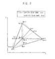
- FIG. 2 is a chromaticity diagram illustrating color gamuts of a left-eye light and a right-eye light generated from the light source part in FIG. 1 ;
- FIG. 3 is a block diagram illustrating the color data correcting unit of FIG. 1 ;
- FIG. 4 is a conceptual view illustrating a look-up table applied to the 3D color correcting unit of FIG. 3 ;
- FIG. 5A to FIG. 5C are block diagrams illustrating the 3D color correcting unit according to various example embodiments of the present invention.
- FIG. 6 is a conceptual view for illustrating a two-dimension (2D) bi-linear interpolation method by the 3D color correcting unit in FIG. 3 ;
- FIGS. 7A and 7B are conceptual views for illustrating a 3D diagonal interpolation method by the 3D color correcting unit in FIG. 3 ;
- FIGS. 8A, 8B, 8C and 8D are conceptual views for describing a bi-linear interpolation method according to the sub areas shown in FIG. 7B ;
- FIG. 9 is a conceptual view describing a method of driving the display apparatus in FIG. 1 ;
- FIG. 10A to FIG. 10E are block diagrams illustrating various example embodiments for the light source part described in connection with FIG. 1 ;
- FIG. 11 is a conceptual view for describing a method of driving a display apparatus according to an example embodiment
- FIG. 12 is a conceptual view for describing a method of driving a display apparatus according to an example embodiment
- FIG. 13 is a conceptual view for describing a method of driving a display apparatus according to an example embodiment
- FIG. 14 is a block diagram illustrating a display apparatus according to an example embodiment
- FIGS. 15A and 15B are block diagrams illustrating various example embodiments for the light source part described in connection with FIG. 14 ;
- FIG. 16 is a conceptual view for describing a method of driving the display apparatus described in connection with FIG. 14 ;
- FIG. 17 is a conceptual view for describing a method of driving a display apparatus according to an example embodiment
- FIG. 18 is a conceptual view for describing a method of driving a display apparatus according to an example embodiment
- FIG. 19 is a conceptual view for describing a method of driving a display apparatus according to an example embodiment
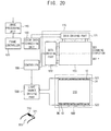
- FIG. 20 is a block diagram illustrating a display apparatus according to an example embodiment
- FIG. 21 is a conceptual view for describing a method of driving a display apparatus described in FIG. 20 ;
- FIG. 22 is a conceptual view for describing a method of driving a display apparatus according to an example embodiment
- FIG. 23 is a conceptual view for describing a method of driving a display apparatus according to an example embodiment.
- FIG. 24 is a conceptual view for describing a method of driving a display apparatus according to an example embodiment.
- FIG. 1 is a block diagram illustrating a display apparatus according to an example embodiment of the present invention.
- the display apparatus includes a display panel 100 , an image processing unit 110 , a frame controller 120 , a controller 130 , a color data correcting unit 150 , a panel driving part 170 , a light source driving part 230 , and a glasses part 300 .
- the display panel 100 includes a plurality of pixels that display an image.
- each of pixels may include a thin transistor TR connected to a data line DL and a gate line GL, a liquid crystal capacitor CLC having a first end connected to the thin transistor TR and a second end to which a common voltage Vcom is applied.
- the image processing unit 110 receives compressed data, and generates left-eye data and right-eye data using the compressed data. For example, by using compressed data of 60 Hz, left-eye data and right-eye data of 120 Hz are generated.
- data of 60 Hz are image data to display an image frame with a frequency of 60 Hz
- data of 120 Hz are image data to display an image frame with a frequency of 120 Hz
- data of 240 Hz are image data to display an image frame with a frequency of 240 Hz.
- Data of 480 Hz are image data to display an image frame with a frequency of 480 Hz.
- the frame controller 120 receives the left-eye data and the right-eye data.
- the frame controller 120 generates k left-eye data frames using the left-eye data, and k right-eye data frames using the right-eye data.
- k is a natural number not less than 2.
- a data frame corresponds to an image frame displayed on the display panel 100 .
- the frame controller 120 generates a first left-eye data frame, a second left-eye data frame, a first right-eye data frame, and a second right-eye data frame by repeatedly using each of the left-eye data and the right-eye data two times.
- the frame controller 120 generates a first left-eye data frame, a second left-eye data frame, a third left-eye data frame, a fourth left-eye data frame, a first right-eye data frame, a second right-eye data frame, a third right-eye data frame, and a fourth right-eye data frame by repeatedly using each of the left-eye data and the right-eye data four times.
- the controller 130 controls an operation of the color data correcting unit 150 based on a synchronization signal provided from the frame controller 120 .
- the controller 130 controls driving timing of the display apparatus.
- the color data correcting unit 150 corrects color data of the data frame for the color balancing of the data frame provided from the frame controller 120 . For example, in a 2D image mode, the color data correcting unit 150 uniformly corrects color coordinates of an achromatic color and a chromatic color by correcting red, green and blue data included in the data frame, and in a 3D image mode, the color data correcting unit 150 corrects a color difference between the left-eye data frame and the right-eye data frame, so that the color coordinates of the achromatic color and chromatic color are uniformly corrected.
- the color data correcting unit 150 is described below in detail.
- the panel driving part 170 includes a data driving part 171 and a gate driving part 173 .
- the panel driving part 170 displays the data frame corrected by the color data correcting unit 150 on the display panel 100 .
- the data driving part 171 converts color data of the corrected data frame into an analog-type data voltage under the control of the controller 130 and then provides the data voltage to the data line DL.
- the gate driving part 173 generates a gate signal under the control of the controller 130 and provides the gate signal to the gate line GL.
- the panel driving part 170 displays an image frame on the display panel 100 using a progressive scan method.
- the panel driving part 170 inserts a black data frame between the left-eye data frame and the right-eye data frame provided from the frame controller 120 , and outputs the black data frame, the left-eye data frame, and the right-eye data frame.
- the panel driving part 170 sequentially provides the display panel 100 with data voltages corresponding to a left-eye data frame, a black data frame, a right-eye data frame, and a black data frame.
- the panel driving part 170 sequentially provides the display panel 100 with data voltages corresponding to a first left-eye data frame, a second left-eye data frame, a third left-eye data frame, a first black data frame, a first right-eye data frame, a second right-eye data frame, a third right-eye data frame, and a second black data frame.
- the light source part 200 includes a light guide plate 201 and a plurality of light emitting modules 211 , 212 , 213 , and 214 .
- a first light emitting module 211 is disposed at a first side of the light guide plate 201
- a second light emitting module 212 is disposed at a second side of the light guide plate 201 to be opposite to the first light emitting module 211
- a third light emitting module 213 is disposed at a third side of the light guide plate 201 to be adjacent to the first light emitting module 211
- a fourth light emitting module 214 is disposed at a fourth side of the light guide plate 201 to be opposite to the third light emitting module 213 .
- Each of the light emitting modules includes a plurality of first light sources 10 and a plurality of second light sources 20 .
- the first light sources 10 generate a first light having a first wavelength band
- the second light sources 20 generate a second light having a second wavelength band.
- each of the first light sources 10 includes a light emitting diode LED and a band pass filter that filters a light generated from the light emitting diode LED to extract the first light
- each of the second light sources 20 includes a light emitting diode LED and a band pass filter that filters a light generated from the light emitting diode LED to extract the second light.
- the first light sources are also referred as left-eye light sources, the first light is also referred as a left-eye light, the second light sources are also referred as right-eye light sources, and the second light is also referred as a right-eye light.
- the light source driving part 230 controls an operation of the light source part 200 under the control of the controller 130 .
- the light source driving part 230 generates a left-eye light source signal for driving the first light source 10 , and a right-eye light source signal for driving the second light source 20 .
- a left-eye light source signal and the right-eye light source signal which are synchronized with each other, are generated to simultaneously drive the first light source 10 and the second light source 20 .
- the left-eye light source signal and the right-eye light source signal which are respectively synchronized with a left-eye image and a right-eye image displayed on the display panel 100 , are generated.
- the glasses part 300 includes a left-eye shutter 310 and a right-eye shutter 320 .
- the left-eye shutter 310 includes a first band pass filter to filter the left-eye light having the first wavelength band
- the right-eye shutter 320 includes a second band pass filter to filter the right-eye light having the second wavelength band.
- the glasses part 300 opens the left-eye shutter 310 and closes the right-eye shutter 320 when the left-eye image is displayed on the display panel 100
- FIG. 2 is a chromaticity diagram illustrating color gamuts of a left-eye light and a right-eye light generated from the light source part in FIG. 1 .
- the left-eye light source 10 generates a left-eye light having a first wavelength band
- the right-eye light source 20 generates a right-eye light having a second wavelength band.
- the left-eye light and the right-eye light having wavelength bands different from each other have chromaticity diagrams inconsistent to each other.
- the chromaticity diagram of the left-eye light LCG has a left-eye color gamut A LEFT
- the chromaticity diagram of the right-eye light RCG has a right-eye color gamut A RIGHT
- the chromaticity diagram of the left-eye light LCG has a first red coordinate R LEFT , a first green coordinate G LEFT , a first blue coordinate B LEFT , a first cyan coordinate C LEFT , a first magenta coordinate M LEFT , a first yellow coordinate Y LEFT , and a first white coordinate W LEFT .
- the chromaticity diagram of the right-eye light RCG has a second red coordinate R RIGHT , a second green coordinate G RIGHT , a second blue coordinate B RIGHT , a second cyan coordinate C RIGHT , a second magenta coordinate M RIGHT , a second yellow coordinate Y RIGHT , and a second white coordinate W RIGHT at different positions from positions where the coordinates of the same colors are located in the chromaticity diagram of the left-eye light LCG.
- the color data correcting unit 150 may correct color data for a 3D image and color data for a 2D image, so that a display quality of a color image may be enhanced.
- FIG. 3 is a block diagram illustrating the color data correcting unit of FIG. 1 .
- FIG. 4 is a conceptual view illustrating a look-up table applied to the 3D color correcting unit of FIG. 3 .
- the color data correcting unit 150 includes a two-dimensional (2D) color correcting unit 151 , a left-eye/right-eye determiner 153 , and a three-dimensional (3D) color correcting unit 155 .
- the 2D color correcting unit 151 includes a first look-up table LUT 1 storing color correcting data mapped to grayscale values.
- the first look-up table LUT 1 stores the color correcting data to adjust a white balance, and color coordinates may be corrected uniformly using the color correcting data stored in the first look-up table LUT 1 . For example, in a 2D mode, when 2D color data is inputted, the color correcting data mapped to a grayscale value of the inputted color data is outputted.
- the first look-up table LUT 1 has color correcting data mapped to sampled grayscale values of predetermined grayscale values to minimize a size of memory, and color correcting data for the other grayscale values not stored in the first look-up table LUT 1 are produced using an arithmetic logic.
- the left-eye/right-eye determiner 153 determines if inputted data is left-eye data or right-eye data. For example, in a 3D mode, the left-eye/right-eye determiner 153 determines if inputted data is left-eye data or right-eye data by using a toggle signal and/or a 3D enable signal, which are informative signals inputted together with the data.
- the 3D color correcting unit 155 corrects at least one of the left-eye color data and right-eye color data according to determination of the left-eye/right-eye determiner 153 .
- the 3D color correcting unit 155 corrects at least one of the left-eye color data and right-eye color data, such that a color displayed by a left-eye light and a color displayed by a right-eye light have the same color coordinate with respect to the same color. Accordingly, a color difference between a left-eye image and a right-eye image may be removed.
- the 3D color correcting unit 155 includes, for example, red, green, and blue second look-up tables LUT 2 corresponding to inputted color data, for example, red, green, and blue data, respectively. Since the inputted data includes 3D data such as red, green, and blue data, a 3D look-up table may be applied to each of the red, green and blue second look-up tables LUT 2 .
- red compensating data mapped to the red, green, and blue data is outputted using the red second look-up table LUT 2
- green compensating data mapped to the red, green, and blue data is outputted using the green second look-up table LUT 2
- blue compensating data mapped to the red, green, and blue data is outputted using the blue second look-up table LUT 2 .
- a second look-up table LUT 2 illustrated in FIG. 4 is assumed to be red second look-up table.
- the second look-up table LUT 2 grayscale values of red data are arranged in an X axis direction, grayscale values of blue data are arranged in a Y axis direction, and grayscale values of green data are arranged in a Z axis direction.
- red, green, and blue data R, G, B
- “161” is outputted as red compensating data R′ using the second look-up table LUT 2 as shown in FIG. 4 .
- green compensating data G′ for example, “128”
- blue compensating data B′ for example, “0”, mapped to the inputted data (128, 128, 0)—may be likewise obtained by using the green second look-up table LUT 2 and the blue second look-up table LUT 2 , respectively. Therefore, the 3D color correcting unit 155 may output the red, green, and blue compensating data (R′, G′, B′) of (161, 128, 0) with respect to the inputted red, green, and blue data (R, G, B) of (128, 128, 0) using the red, green and blue second look-up tables LUT 2 .
- the second look-up tables LUT 2 are embodied to have a (5 ⁇ 5 ⁇ 5) size as shown in FIG. 4 .
- the embodiments of the present invention are not limited thereto, and various sizes of second look-up tables LUT 2 , such as, for example, a (9 ⁇ 9 ⁇ 9) size, may be available according to the memory capacity.
- the red, green, and blue compensating data respectively corresponding to red, green, and blue data not stored in the second look-up table LUT 2 due to the limitation of memory capacity are generated by an interpolation method.
- FIG. 5A is a block diagram illustrating the 3D color correcting unit described in FIG. 3 .
- the 3D color correcting unit 155 includes a left-eye color correcting unit 155 A.
- the left-eye color correcting unit 155 A includes left-eye second look-up tables L_LUT 2 .
- the left-eye second look-up tables L_LUT 2 include red, green, and blue second look-up tables L_LUT 2 as described in FIG. 4 .
- Left-eye red, green, and blue correcting data stored in the red, green, and blue second look-up tables L_LUT 2 are obtained by correcting the left-eye red, green, and blue data, respectively, such that a color coordinate of a color displayed by the left-eye light is shifted to a color coordinate of a color displayed by the right-eye light as shown in FIG. 2 .
- the 3D color correcting unit 155 generates the left-eye red, green, and blue correcting data using the inputted left-eye red, green, and blue data through the left-eye second look-up tables L_LUT 2 , and outputs the correcting data.
- the right-eye red, green, and blue data received in the 3D color correcting unit 155 are bypassed.
- the right-eye red, green, and blue data may be corrected to right-eye red, green, and blue correcting data to adjust a white balance through the first look-up table LUT 1 of the 2D color correcting unit 151 .
- the 3D color correcting unit 155 corrects the left-eye color data, so that a color displayed by a left-eye light, and a color displayed by a right-eye light with respect to the same color coincide with each other.
- FIG. 5B is a block diagram illustrating a 3D color correcting unit according to an example embodiment of the present invention.
- the 3D color correcting unit 156 includes a right-eye color correcting unit 156 A.
- the right-eye color correcting unit 156 A includes right-eye second look-up tables R_LUT 2 .
- the right-eye second look-up tables R_LUT 2 include red, green, and blue second look-up tables R_LUT 2 as described in FIG. 4 .
- Right-eye red, green, and blue correcting data stored in the red, green, and blue second look-up tables R_LUT 2 are obtained by correcting the right-eye red, green, and blue data, respectively, such that a color coordinate of a color displayed by the right-eye light is shifted to a color coordinate of a color displayed by the left-eye light as shown in FIG. 2 .
- the 3D color correcting unit 156 generates the right red, green, and blue correcting data using the inputted right-eye red, green, and blue data through the right-eye second look-up tables R_LUT 2 , and outputs the correcting data.
- the left-eye red, green, and blue data received in the 3D color correcting unit 156 are bypassed.
- the left-eye red, green, and blue data may be corrected to left-eye red, green, and blue correcting data to adjust a white balance through the first look-up table LUT 1 of the 2D color correcting unit 151 .
- the 3D color correcting unit 156 corrects the right-eye color data, so that a color displayed by a left-eye light, and a color displayed by a right-eye light with respect to the same color coincide with each other.
- FIG. 5C is a block diagram illustrating a 3D color correcting unit according to an example embodiment of the present invention.
- the 3D color correcting unit 157 includes a left-eye color correcting unit 157 A and a right-eye color correcting unit 157 B.
- the left-eye color correcting unit 157 A includes left-eye second look-up tables L_LUT 2 .
- the left-eye second look-up tables L_LUT 2 include red, green, and blue second look-up tables L_LUT 2 as described in FIG. 4 .
- Left-eye red, green, and blue correcting data are mapped to left-eye red, green, and blue data in the left-eye second look-up tables L_LUT 2 .
- the left-eye red, green, and blue correcting data are obtained by correcting the left-eye red, green, and blue data, respectively, such that a first color coordinate of a color displayed by the left-eye light is shifted to an intermediate position between the first color coordinate and a second color coordinate of a color displayed by the right-eye light as shown in FIG. 2 , and thus, the first color coordinate of the left-eye light coincides with an arbitrary third color coordinate.
- the right-eye color correcting unit 157 B includes right-eye second look-up tables R_LUT 2 .
- the right-eye second look-up tables R_LUT 2 include red, green, and blue second look-up tables R_LUT 2 as described in FIG. 4 .
- Left-eye red, green, and blue correcting data are mapped to right-eye red, green, and blue data in the right-eye second look-up tables R_LUT 2 .
- the right-eye red, green, and blue correcting data are obtained by correcting the right-eye red, green, and blue data, respectively, such that the second color coordinate of the color displayed by the right-eye light is shifted to the intermediate position between the first color coordinate of the color displayed by the left-eye light and the second color coordinate as shown in FIG. 2 , and thus, the second color coordinate of the right-eye light coincides with the arbitrary third color coordinate.
- the 3D color correcting unit 157 corrects the left-eye and right-eye color data so that a color displayed by the left-eye light and a color displayed by the right-eye light have the same color coordinate with respect to the same color. Accordingly, a color difference between a left-eye image and a right-eye image may be removed.
- the 3D color correcting unit 157 may generate the red, green, and blue correcting data by an interpolation method using the color correcting data stored in the red, green, and blue second look-up tables LUT 2 .
- color correcting data may be generated by a one-dimensional (1D) bi-linear interpolation method.
- color correcting data may be generated by a two-dimensional (2D) bi-linear interpolation method.
- color correcting data may be generated by a three-dimensional (3D) diagonal interpolation method.
- FIG. 6 is a conceptual view for illustrating a two-dimensional (2D) bi-linear interpolation method by the 3D color correcting unit in FIG. 3 .
- FIG. 6 illustrates a process of generating color correcting data by a 2D bi-linear interpolation method when only one of corresponding grayscale values of inputted red, green, and blue data exists in the second look-up table LUT 2 .
- first, second, third, and fourth parameters f00, f01, f10, and f11 are used for the 2D bi-linear interpolation method.
- the first, second, third, and fourth parameters f00, f01, f10, and f11 represent compensating data sampled with respect to a red axis (Rx) and a green axis (Gy) in the second look-up table LUT 2 .
- Compensating data F apart from f00 by x along the red axis (Rx) and by y along the green axis (Gy) is calculated by the following Equation 1 using the first, second, third, and fourth parameters f00, f01, f10, and f11:
- FIGS. 7A and 7B are conceptual views illustrating a 3D diagonal interpolation method by the 3D color correcting unit in FIG. 3 .
- FIGS. 7A and 7B illustrate a process of generating color correcting data by a 3D diagonal interpolation method when none of grayscale values of inputted red, green, and blue data exist in the second look-up table LUT 2 .
- first, second, third, fourth, fifth, sixth, seventh, and eighth parameters f000, f001, f010, f011, f100, f101, f110, and f111 are used for the 3D interpolation method.
- the first, second, third, fourth, fifth, sixth, seventh, and eighth parameters f000, f001, f010, f011, f100, f101, f110, and f111 represent compensating data sampled with respect to a red axis (Rx), a green axis (Gy), and a blue axis (Bz) in the second look-up table LUT 2 .
- Compensating data F apart from f000 by x along the red axis (Rx), by y along the green axis (Gy), and by z along the blue axis (Bz) is generated using the first to eighth parameters f000, f001, f010, f011, f100, f101, f110, and f111 as follows.
- a main area MA which is a two-dimensional (2D) area and includes blue data whose value is ‘z’, is considered as shown in FIG. 7B .
- the main area MA includes first, second, third, and fourth sub parameters a, b, c, and d.
- the first, second, third, and fourth sub parameters a, b, c, and d are calculated in the following Equation 2.
- Equation 2 ‘N’ is a distance between two neighboring sampled grayscale values in the second look-up table LUT 2 .
- ‘N’ may be 64 in the case of a look-up table having a (5 ⁇ 5 ⁇ 5) size with respect to total 256 grayscale values.
- Fifth and sixth sub parameters ab and ac are apart from the first sub parameter a by z along the red axis (Rx) and along the green axis (Gy), respectively, a seventh sub parameter bd is apart from the second sub parameter b by z along the green axis (Gy), and an eighth sub parameter cd is apart from the third sub parameter c by z along the red axis (Rx).
- the fifth, sixth, seventh, and eighth sub parameters are calculated in the following Equation 3:
- a ninth parameter e is a diagonal component between the first parameter f000 and the eighth parameter f111.
- the ninth parameter e is located at an intersection of a virtual line linking between the first parameter f000 and the eighth parameter f111 and the main area MA.
- e z′ [Equation 4]
- the ninth parameter e is acquired through the first look-up table LUT 1 for white balance of the 2D color correcting unit 151 shown in FIG. 3 .
- correcting data stored in the first look-up table LUT 1 for white balance to the achromatic color, a deterioration of the white balance by the 3D diagonal interpolation method may be prevented.
- the main area MA is divided into four sub areas that are first, second, third, and fourth sub areas SA 1 , SA 2 , SA 3 , and SA 4 .
- the compensating data F is calculated as follows.
- FIGS. 8A, 8B, 8C, and 8D are conceptual views for describing a bi-linear interpolation method according to the sub areas shown in FIG. 7B
- the compensating data F is calculated in the following Equation 5:
- FIG. 9 is a conceptual view describing a method of driving the display apparatus in FIG. 1 .
- the display panel 100 has a resolution of 1920 ⁇ 1080.
- the panel driving part 170 provides the display panel 100 with data of first and second left-eye data frames LD 1 and LD 2 and data of first and second right-eye data frames RD 1 and RD 2 that each have a frequency of 240 Hz and are corrected by the color data correcting unit 150 .
- the first and second left-eye data frames LD 1 and LD 2 each correspond to a white frame image
- the first and second right-eye data frames RD 1 and RD 2 each correspond to a black frame image.
- a sub interval in which the panel driving part 170 outputs a data frame to the display panel 100 is about 4 ms, and a main interval in which data frames LD 1 , LD 2 , RD 1 , and RD 2 of a stereoscopic image are displayed on the display panel 100 may be about 16 ms. Therefore, the display panel 100 may be driven with a frame frequency of about 240 Hz.
- the panel driving part 170 sequentially outputs data of data frames from a first horizontal line to a last horizontal line (e.g., 1080th line) of the display panel 100 during sub intervals.
- Data of the first and second left-eye data frames LD 1 and LD 2 have a high voltage VDD corresponding to a white image
- data of the first and second right-eye data frames RD 1 and RD 2 have a low voltage VSS corresponding to a black image.
- the panel driving part 170 provides the display panel 100 with data of the first left-eye data frame LD 1 during a first sub interval S 1 , data of the second left-eye data frame LD 2 during a second sub interval S 2 , data of the first right-eye data frame RD 1 during a third sub interval S 3 , and data of the second right-eye data frame RD 2 during a fourth sub interval S 4 .
- the display panel 100 displays an image corresponding to the data.
- the image display is delayed by a liquid crystal response time from when the data is applied to the display panel 100 .
- a left-eye image corresponding to the previous second left-eye data frame LD 2 is converted to a right-eye image corresponding to the first right-eye data frame RD 1 in an upper area UA of the display panel 100 , and the left-eye image of the previous frame is displayed in middle and lower areas MA and LA during the early part of the third sub interval S 3 .
- the right-eye image is displayed in the upper area UA of the display panel 100 , the left-eye image is converted to the right-eye image in the middle area MA, and the left-eye image of the previous frame is displayed in the lower area LA during the middle part of the third sub interval S 3 .
- the right-eye image is displayed in the upper and middle areas UA and MA of the display panel 100 , and the left-eye image of the previous frame is converted to the right-eye image in the lower area LA during the latter part of the third sub interval S 3 .
- the display panel 100 displays a left-eye image during a first interval P 11 , displays right-eye and mixed images during a second interval P 12 , displays the right-eye image during a third interval P 13 , and displays the left-eye and mixed images during a fourth interval P 14 .
- the first to fourth intervals P 11 , P 12 , P 13 , and P 14 may be set differently according to the liquid crystal response time.
- the term “mixed images” may be used to represent a situation where a left-eye image and a right-eye image are displayed together on the display panel 100 .
- the light source driving part 230 In synchronization with an interval in which an image is displayed on the display panel 100 , the light source driving part 230 generates a left-eye light source signal LLS for driving the left-eye light source 10 and a right-eye light source signal RLS for driving the right-eye light source 20 .
- the left-eye light source signal LLS is at a high level during the first interval P 11 in which the left-eye image is displayed on the display panel 100 , and is at a low level during the second interval P 12 in which the right-eye and mixed images are displayed on the display panel 100 .
- the right-eye light source signal RLS is at a high level during the third interval P 13 in which the right-eye image is displayed on the display panel 100 , and is at a low level during the fourth interval P 14 in which the left-eye and mixed images are displayed on the display panel 100 .
- the light source part 200 provides the display panel 100 with a left-eye light during the first interval P 11 and blocks the left-eye light during the second interval P 12 .
- the light source part 200 provides the display panel 100 with a right-eye light during the third interval P 13 and blocks the right-eye light during the fourth interval P 14 . Therefore, the light source part 200 provides the display panel 100 with the left-eye light or right-eye light when the left-eye or right-eye image is displayed on the display panel 100 , and does not provide the display panel 100 with the left-eye light and right-eye light when the mixed image is displayed on the display panel 100 .
- the glasses part 300 opens and closes the left-eye shutter 310 and the right-eye shutter 320 .
- the left-eye shutter signal LSS is at a high level and the left-eye image is displayed on the display panel 100 during a period from a partial section of the first sub interval S 1 to a partial section of the third sub interval S 3
- the left-eye shutter signal LSS is at a low level and the right-eye image is displayed on the display panel 100 during a period from a partial section of the third sub interval S 3 to a partial section of the fifth sub interval S 5 .
- the right-eye shutter signal RSS is at a low level during the period from a partial section of the first sub interval S 1 to a partial section of the third sub interval S 3 , and is at a high level during the period from a partial section of the third sub interval S 3 to a partial section of the fifth sub interval S 5 . Accordingly, the glasses part 300 opens the left-eye shutter 310 and closes the right-eye shutter 320 while the left-eye image is displayed on the display panel 100 , and opens the right-eye shutter 320 and closes the left-eye shutter 310 while the right-eye image is displayed on the display panel 100 .
- the light source part 200 provides a light to the display panel 100 only when the left-eye image or right-eye image is displayed on the display panel 100 , no crosstalk is perceived between the left-eye image and the right-eye image.
- FIG. 10A to FIG. 10E are block diagrams illustrating various example embodiments for the light source part described in connection with FIG. 1 .
- a light source part 240 includes a plurality of left-eye light sources 10 and a plurality of right-eye light sources 20 .
- Each of the light sources may be a light emitting diode (LED). Alternately, the light sources may be fluorescent lamps generating a left-eye light and a right-eye light.
- the light source part 240 has a direct-type structure that is placed under the display panel 100 .
- a light source part 250 includes a light guide plate 251 under the display panel 100 and a light emitting module 252 on a short side of the light guide plate 251 .
- the light emitting module 252 includes a plurality of left-eye light sources 10 and a plurality of right-eye light sources 20 .
- Each of the light sources includes a light emitting diode (LED).
- LED light emitting diode
- fluorescent lamps generating a left-eye light and a right-eye light may be placed on the short side of the light guide plate 251 instead of the light emitting module 252 .
- a light source part 260 includes a light guide plate 261 under the display panel 100 , a first light emitting module 262 on a first short side of the light guide plate 261 , and a second light emitting module 263 on a second short side of the light guide plate 261 .
- Each of the first and second light emitting modules 262 and 263 includes a plurality of left-eye light sources 10 and a plurality of right-eye light sources 20 .
- Each of the light sources includes a light emitting diode (LED).
- LED light emitting diode
- fluorescent lamps generating a left-eye light and a right-eye light may be placed on the first and second short sides of the light guide plate 261 , respectively, instead of the first and second light emitting modules 262 and 263 .
- a light source part 270 includes a light guide plate 271 under the display panel 100 and a light emitting module 272 on a long side of the light guide plate 271 .
- the light emitting module 272 includes a plurality of left-eye light sources 10 and a plurality of right-eye light sources 20 .
- Each of the light sources includes a light emitting diode (LED).
- LED light emitting diode
- fluorescent lamps generating a left-eye light and a right-eye light may be placed on the long side of the light guide plate 271 instead of the light emitting module 272 .
- a light source part 280 includes a light guide plate 281 under the display panel 100 , a first light emitting module 282 on a first long side of the light guide plate 281 , and a second light emitting module 283 on a second long side of the light guide plate 281 .
- Each of the first and second light emitting modules 282 and 283 includes a plurality of left-eye light sources 10 and a plurality of right-eye light sources 20 .
- Each of the light sources includes a light emitting diode (LED).
- LED light emitting diode
- fluorescent lamps generating a left-eye light and a right-eye light may be placed on the first and second long sides of the light guide plate 281 , respectively, instead of the first and second light emitting modules 282 and 283 .
- FIG. 11 is a conceptual view for describing a method of driving a display apparatus according to an example embodiment.
- the display panel 100 may have a resolution of 1920 ⁇ 1080.
- the panel driving part 170 provides the display panel 100 with a first left-eye data frame LD 1 , a first black data frame BD 1 , a first right-eye data frame RD 1 , and a second black data frame BD 2 using first and second left-eye data frames LD 1 and LD 2 and first and second right-eye data frames RD 1 and RD 2 that each have a frequency of 240 Hz and are corrected by the color data correcting unit 150 .
- the first left-eye data frame LD 1 corresponds to a white data frame image
- the first right-eye data frame RD 1 corresponds to a black data frame image.
- the panel driving part 170 provides the display panel 100 with data of the first black data frame BD 1 during a first sub interval S 1 , data of the first left-eye data frame LD 1 during a second sub interval S 2 , data of the second black data frame BD 2 during a third sub interval S 3 , and data of the first right-eye data frame RD 1 during a fourth sub interval S 4 .
- the display panel 100 displays an image corresponding to the data.
- the image display is delayed by a liquid crystal response time from when the data is applied to the display panel 100 .
- a left-eye image corresponding to the first left-eye data frame LD 1 that is a previous frame is converted to a black image corresponding to the second black data frame BD 2 in an upper area UA of the display panel 100 , and the left-eye image of the previous frame is displayed in middle and lower areas MA and LA of the display panel 100 during the early part of the third sub interval S 3 .
- the black image is displayed in the upper area UA of the display panel 100 , the left-eye image is converted to the black image in the middle area MA, and the left-eye image of the previous frame is displayed in the lower area LA during the middle part of the third sub interval S 3 .
- the black image is displayed in the upper and middle areas UA and MA of the display panel 100 , and the left-eye image of the previous frame is converted to the black image in the lower area LA during the latter part of the third sub interval S 3 .
- the display panel 100 displays a left-eye image during a first interval P 21 , displays right-eye and mixed images during a second interval P 22 , displays the right-eye image during a third interval P 23 , and displays the left-eye and mixed images during a fourth interval P 14 .
- the first to fourth intervals P 21 , P 22 , P 23 , and P 24 may be set differently according to the liquid crystal response time.
- a black image is inserted between the first left-eye image and the first right-eye image, so that the display panel 100 displaying the first left-eye image is reset to the black image.
- the first interval or third interval P 21 or P 23 in which the left-eye image or right-eye image is displayed on the display panel 100 may be increased.
- the second interval or fourth interval P 22 or P 24 in which the first left-eye image (or the first right-eye image) is converted to the first right-eye image (or the first left-eye image) may be shortened.
- the light source driving part 230 generates a left-eye light source signal LLS and a right-eye light source signal RLS.
- the left-eye light source signal LLS is at a high level during the first interval P 21 in which the left-eye image is displayed on the display panel 100 , and is at a low level during the second interval P 22 in which the right-eye image and mixed image are displayed on the display panel 100 .
- the right-eye light source signal RLS is at a high level during the third interval P 23 in which the right-eye image is displayed on the display panel 100 , and is at a low level during the fourth interval P 24 in which the left-eye image and mixed image are displayed on the display panel 100 .
- the light source part 200 provides the display panel 100 with a left-eye light during the first interval P 21 , and blocks the left-eye light during the second interval P 22 .
- the light source part 200 provides the display panel 100 with a right-eye light during the third interval P 23 , and blocks the right-eye light during the fourth interval P 24 . Therefore, the light source part 200 provides the display panel 100 with the left-eye light or right-eye light during the interval in which the left-eye image or right-eye image is displayed on the display panel 100 , and does not provide the display panel 100 with the left-eye light or right-eye light during the interval in which the mixed image is displayed on the display panel 100 .
- the glasses part 300 opens and closes the left-eye shutter 310 and the right-eye shutter 320 .
- the left-eye shutter signal LSS is at a high level from a partial section of the second sub interval S 2 to a partial section of the third sub interval S 3 in which the left-eye image is displayed on the display panel 100 , and is at a low level during a period from a partial section of the fourth sub interval S 4 to a partial section of the fifth sub interval S 5 in which the right-eye image is displayed on the display panel 100 .
- the right-eye shutter signal RSS is at a low level during the period from a partial section of the second sub interval S 2 to a partial section of the third sub interval S 3 , and is at a high level during the period from a partial section of the fourth sub interval S 4 to a partial section of the fifth sub interval S 5 . Accordingly, the glasses part 300 opens the left-eye shutter 310 and closes the right-eye shutter 320 while the left-eye image is displayed on the display panel 100 , and opens the right-eye shutter 320 and closes the left-eye shutter 310 while the right-eye image is displayed on the display panel 100 .
- the light source part 200 provides a light to the display panel 100 only when the left-eye image or right-eye image is displayed on the display panel 100 , no crosstalk is perceived between the left-eye image and the right-eye image.
- the black image is inserted between the left-eye image and the right-eye image, so that luminance efficiency may be improved.
- FIG. 12 is a conceptual view for describing a method of driving a display apparatus according to an example embodiment.
- the display panel 100 has a resolution of 1920 ⁇ 1080.
- the panel driving part 170 provides the display panel 100 with first, second, third, and fourth left-eye data frames LD 1 , LD 2 , LD 3 , and LD 4 and first, second, third, and fourth right-eye data frames RD 1 , RD 2 , RD 3 and RD 4 that each have a frequency of 480 Hz and are corrected by the color data correcting unit 150 .
- a sub interval in which the panel driving part 170 provides the display panel 100 with a data frame is about 2 ms
- a main interval in which data frames of a stereoscopic image LD 1 , LD 2 , LD 3 , LD 4 , RD 1 , RD 2 , RD 3 , and RD 4 are provided to the display panel 100 may be about 16 ms.
- the panel driving part 170 provides the display panel 100 with data of the first left-eye data frame LD 1 during a first sub interval S 1 , data of the second left-eye data frame LD 2 during a second sub interval S 2 , data of the third left-eye data frame LD 3 during a third sub interval S 3 , data of the fourth left-eye data frame LD 4 during a fourth sub interval S 4 , data of the first right-eye data frame RD 1 during a fifth sub interval S 5 , data of the second right-eye data frame RD 2 during a sixth sub interval S 6 , data of the third right-eye data frame RD 3 during a seventh sub interval S 7 , and data of the fourth right-eye data frame RD 4 during an eighth sub interval S 8 .
- the display panel 100 displays an image corresponding to the data.
- the image display is delayed by a liquid crystal response time from when the data is applied to the display panel 100 .
- a left-eye image corresponding to the fourth left-eye data frame LD 4 of the previous frame is converted to a right-eye image corresponding to the first right-eye data frame RD 1 of the present frame in an upper area UA of the display panel 100 , and the left-eye image of the previous frame is displayed in middle and lower areas MA and LA during the early part of the fifth sub interval S 5 .
- the right-eye image is displayed in the upper area UA of the display panel 100 , the left-eye image is converted to the right-eye image in the middle area MA, and the left-eye image of the previous frame is displayed in the lower area LA during the middle part of the fifth sub interval S 5 .
- the right-eye image is displayed in the upper and middle areas UA and MA of the display panel 100 , and the left-eye image of the previous frame is converted to the right-eye image in the lower area LA during the latter part of the fifth sub interval S 5 .
- the display panel 100 displays a left-eye image during a first interval P 31 , displays right-eye and mixed images during a second interval P 32 , displays the right-eye image during a third interval P 33 , and displays the left-eye and mixed images during a fourth interval P 34 .
- the first to fourth intervals P 31 , P 32 , P 33 , and P 34 may be set differently according to the liquid crystal response time.
- the light source driving part 230 generates a left-eye light source signal LLS and a right-eye light source signal RLS.
- the left-eye light source signal LLS is at a high level during the first interval P 31 in which the left-eye image is displayed on the display panel 100 , and is at a low level during the second interval P 32 in which the right-eye and mixed images are displayed on the display panel 100 .
- the right-eye light source signal RLS is at a high level during the third interval P 33 in which the right-eye image is displayed on the display panel 100 , and is at a low level during the fourth interval P 34 in which the left-eye and mixed images are displayed on the display panel 100 .
- the light source part 200 provides the display panel 100 with a left-eye light during the first interval P 31 , and blocks the left-eye light during the second interval P 32 .
- the light source part 200 provides the display panel 100 with a right-eye light during the third interval P 33 , and blocks the right-eye light during the fourth interval P 34 .
- the glasses part 300 opens and closes the left-eye shutter 310 and the right-eye shutter 320 .
- the left-eye shutter signal LSS opens the left-eye shutter 310 during a period from the first sub interval S 1 to the fourth sub interval S 4 including the first interval P 31 in which the left-eye image is displayed on the display panel 100 and closes the left-eye shutter 310 during a period from the fifth sub interval S 5 to the eighth sub interval S 8 including part of the second interval P 32 in which the right-eye image is displayed on the display panel 100 .
- the right-eye shutter signal RSS closes the right-eye shutter 320 during the period from the first sub interval S 1 to the fourth sub interval S 4 including the first interval P 31 in which the left-eye image is displayed on the display panel 100 and opens the right-eye shutter 320 during the period from the fifth sub interval S 5 to the eighth sub interval S 8 including part of the second interval P 32 in which the right-eye image is displayed on the display panel 100 .
- the light source part 200 provides a light to the display panel 100 only when the interval in which the left-eye image or right-eye image is displayed on the display panel 100 , no crosstalk is perceived between the left-eye image and the right-eye image.
- FIG. 13 is a conceptual view for describing a method of driving a display apparatus according to an example embodiment.
- the display panel 100 has a resolution of 1920 ⁇ 1080.
- the panel driving part 170 provides the display panel 100 with first, second, and third left-eye data frames LD 1 , LD 2 , and LD 3 , a first black data frame BD 1 , first, second, third right-eye data frames RD 1 , RD 2 , and RD 3 , and a second black data frame BD 2 using first, second, third, and fourth left-eye data frames LD 1 , LD 2 , LD 3 , and LD 4 and first, second, third, and fourth right-eye data frames RD 1 , RD 2 , RD 3 , and RD 4 that each have a frequency of 480 Hz and are corrected by the color data correcting unit 150 .
- the panel driving part 170 provides the display panel 100 with data of the first left-eye data frame LD 1 during a first sub interval S 1 , data of the second left-eye data frame LD 2 during a second sub interval S 2 , data of the third left-eye data frame LD 3 during a third sub interval S 3 , data of the first black data frame BD 1 during a fourth sub interval S 4 , data of the first right-eye data frame RD 1 during a fifth sub interval S 5 , data of the second right-eye data frame RD 2 during a sixth sub interval S 6 , data of the third right-eye data frame RD 3 during a seventh sub interval S 7 , and data of the second black data frame BD 2 during an eighth sub interval S 8 .
- the display panel 100 displays an image corresponding to the data.
- the image display is delayed by a liquid crystal response time from when the data is applied to the display panel 100 . Therefore, according to the liquid crystal response time, the display panel 100 has intervals displaying a mixed image of left-eye and right-eye images.
- a third left-eye image corresponding to the third left-eye data frame LD 3 of the previous frame is converted to a first black image corresponding to the first black data frame BD 1 of the present frame in an upper area UA of the display panel 100 , and the third left-eye image of the previous frame is displayed in middle and lower areas MA and LA during the early part of the fourth sub interval S 4 .
- the first black image is displayed in the upper area UA of the display panel 100
- the third left-eye image is converted to the first black image in the middle area MA
- the third left-eye image is displayed in the lower area LA during the middle part of the fourth sub interval S 4 .
- the first black image is displayed in the upper and middle areas UA and MA of the display panel 100 , and the third left-eye image is converted to the first black image in the lower area LA during the latter part of the fourth sub interval S 4 .
- the display panel 100 displays a left-eye image during a first interval P 41 , displays right-eye and mixed images during a second interval P 42 , displays the right-eye image during a third interval P 43 , and displays the left-eye and mixed images during a fourth interval P 44 .
- the first to fourth intervals P 41 , P 42 , P 43 , and P 44 may be set differently according to the liquid crystal response time.
- the first black image is inserted between the first left-eye image and the first right-eye image, and the display panel 100 displaying the first left-eye image is reset to a black image, so that in the case that data of the first right-eye image is black which is the worst case of crosstalk, one more frame is secured for a falling response time of liquid crystal molecules, and thus the first interval or third interval P 41 or P 43 in which the left-eye image or right-eye image is displayed on the display panel 100 may be increased.
- the second interval or fourth interval P 42 or P 44 in which the first left-eye image (or the first right-eye image) is converted to the first right-eye image (or the first left-eye image) may be shortened.
- the light source driving part 230 generates a left-eye light source signal LLS and a right-eye light source signal RLS.
- the left-eye light source signal LLS is at a high level during the first interval P 41 in which the left-eye image is displayed on the display panel 100 , and is at a low level during the second interval P 42 in which the right-eye and mixed images are displayed on the display panel 100 .
- the right-eye light source signal RLS is at a high level during the third interval P 43 in which the right-eye image is displayed on the display panel 100 , and is at a low level during the fourth interval P 44 in which the left-eye and mixed images are displayed on the display panel 100 .
- the light source part 200 provides the display panel 100 with a left-eye light during the first interval P 41 and blocks the left-eye light during the second interval P 42 .
- the light source part 200 provides the display panel 100 with a right-eye light during the third interval P 43 and blocks the right-eye light during the fourth interval P 44 .
- the glasses part 300 opens and closes the left-eye shutter 310 and the right-eye shutter 320 .
- the left-eye shutter signal LSS opens the left-eye shutter 310 during a period from a partial section of the first sub interval S 1 to a partial section of the fifth sub interval S 5 including the first interval P 41 in which the left-eye image is displayed on the display panel 100 and closes the left-eye shutter 310 during a period from a partial section of the fifth sub interval S 5 to a partial section of a ninth sub interval S 9 including the third interval P 43 in which the right-eye image is displayed on the display panel 100 .
- the right-eye shutter signal RSS closes the right-eye shutter 320 during the period from a partial section of the first sub interval S 1 to a partial section of the fifth sub interval S 5 including the first interval P 41 in which the left-eye image is displayed on the display panel 100 and opens the right-eye shutter 320 during the period from a partial section of the fifth sub interval S 5 to a partial section of the ninth sub interval S 9 including the third interval P 43 in which the right-eye image is displayed on the display panel 100 .
- the light source part 200 provides a light to the display panel 100 only when the left-eye image or right-eye image is displayed on the display panel 100 , no crosstalk is perceived between the left-eye image and the right-eye image.
- the black image is inserted between the left-eye image and the right-eye image, so that luminance efficiency may be improved.
- FIG. 14 is a block diagram illustrating a display apparatus according to an example embodiment of the present invention.
- FIGS. 15A and 15B are block diagrams illustrating various example embodiments for the light source part described in connection with FIG. 14 .
- the display apparatus includes an image processing unit 110 , a frame controller 120 , a controller 130 , a color data correcting unit 150 , display panel 100 , a panel driving part 170 , a light source part 400 , a light source driving part 420 , and a glasses part 300 .
- the display apparatus is the same or substantially the same as the display apparatus shown in FIG. 1 except for the light source part 400 and the light source driving part 420 .
- the light source part 400 includes a plurality of left-eye light sources 10 and a plurality of right-eye light sources 20 .
- the light source part 400 has a direct-type structure that is placed under the display panel 100 .
- the light source part 400 includes a plurality of light emitting blocks LB 1 , LB 2 , LB 3 , . . . , and LBm arranged in a scanning direction.
- ‘m’ is a natural number.
- the light source part 400 may include fluorescent lamps that generate a left-eye light and a right-eye light, wherein the fluorescent lamps may be arranged in the scanning direction corresponding to the light emitting blocks.
- the display apparatus may include the light source parts shown in FIGS. 15A and 15B .
- the light source part 430 shown in FIG. 15A includes a light guide plate 431 and a light emitting module 432 on a short side of the light guide plate 431 .
- the light emitting module 432 includes a plurality of left-eye light sources 10 and a plurality of right-eye light sources 20 .
- the light emitting module 432 includes a plurality of light emitting blocks LB 1 , LB 2 , LB 3 , . . . , and LBm arranged in the scanning direction.
- the light source part 440 shown in FIG. 15B includes a light guide plate 441 , a first light emitting module 442 on a first short side of the light guide plate 441 , and a second light emitting module 443 on a second short side of the light guide plate 441 .
- the first light emitting module 442 includes a plurality of left-eye light sources 10 and a plurality of right-eye light sources 20 , and includes m light emitting blocks LB 1 , LB 2 , LB 3 , . . . , and LBm arranged in the scanning direction.
- the second light emitting module 443 includes a plurality of left-eye light sources 10 and a plurality of right-eye light sources 20 , and includes m light emitting blocks LB 1 , LB 2 , LB 3 , . . . , and LBm that respectively face the light emitting blocks LB 1 , LB 2 , LB 3 , . . . , and LBm of the first light emitting module 442 .
- the light emitting blocks LB 1 , LB 2 , LB 3 , . . . , and LBm of the second light emitting module 443 are driven in synchronization with the respective corresponding light emitting blocks LB 1 , LB 2 , LB 3 , . . .
- the first light emitting block LB 1 of the first light emitting module 442 and the first light emitting block LB 1 of the second light emitting module 443 are synchronized with each other when driven by a light source driving signal.
- the light source driving part 420 generates m left-eye light source signals, such as a first to an M-th left-eye light source signals and m right-eye light source signals, such as a first to an M-th right-eye light source signals that correspond to the m light emitting blocks LB 1 , LB 2 , LB 3 , . . . , and LBm.
- the display panel includes m display blocks DB 1 , DB 2 , DB 3 , . . . , and DBm corresponding to the m light emitting blocks LB 1 , LB 2 , LB 3 , . . . , and LBm.
- the light source driving part 420 generates first left-eye and right-eye light source signals that respectively turns on the left-eye sources 10 of the first light emitting block LB 1 and turns off the right-eye light sources 20 of the first light emitting block LB 1 while the left-eye image is displayed on the first display block DB 1 corresponding to the first light emitting block LB 1 .
- FIG. 16 is a conceptual view for describing a method of driving the display apparatus described in connection with FIG. 14 .
- the display panel 100 may have a resolution of 1920 ⁇ 1080.
- the panel driving part 170 provides the display panel 100 with data of first and second left-eye data frames LD 1 and LD 2 of 240 Hz and data of first and second right-eye data frames RD 1 and RD 2 that each have a frequency of 240 Hz and are corrected by the color data correcting unit 150 .
- a sub interval in which the panel driving part 170 outputs a data frame to the display panel 100 is about 4 ms, and a main interval in which data frames LD 1 , LD 2 , RD 1 , and RD 2 of a stereoscopic image are displayed on the display panel 100 may be about 16 ms. Therefore, the display panel may be driven with a frame frequency of about 240 Hz.
- the panel driving part 170 provides the display panel 100 with data of the first left-eye data frame LD 1 during a first sub interval S 1 , data of the second left-eye data frame LD 2 during a second sub interval S 2 , data of the first right-eye data frame RD 1 during a third sub interval S 3 , and data of the second right-eye data frame RD 2 during a fourth sub interval S 4 .
- first display block DB 1 In a first horizontal line included in a first display block DB 1 of the display panel 100 , data of the first and second left-eye data frames LD 1 and LD 2 are provided during the first and second sub intervals S 1 and S 2 , respectively, and data of the first and second right-eye data frames RD 1 and RD 2 are provided during the third and fourth sub intervals S 3 and S 4 , respectively.
- the first display block DB 1 displays an image corresponding to the data. The image display is delayed by a liquid crystal response time from when the data is applied to the display panel 100 .
- the first display block DB 1 has intervals displaying a mixed image of a left-eye image corresponding to the first and second left-eye data frames LD 1 and LD 2 , and a right-eye image corresponding to the first and second right-eye data frames RD 1 and RD 2 .
- the first horizontal line displays the left-eye image during a period from a partial section of the first sub interval S 1 to a partial section of the second sub interval S 2 , and displays the mixed image and left-eye image during a period from a partial section of the second sub interval S 2 to a partial section of the fourth sub interval S 4 .
- the first horizontal line displays the mixed image and left-eye image during a period from a partial section of the previous interval of the first sub interval S 1 to a partial section of the third sub interval S 3 , and displays the right-eye image during a period from a partial section of the third sub interval S 3 to a partial section of the fourth sub interval S 4 .
- the first display block DB 1 displays the left-eye image during a first interval P 51 , displays the right-eye and mixed images during a second interval P 52 , displays the right-eye image during a third interval P 53 , and displays the left-eye and mixed images during a fourth interval P 54 .
- the first to fourth intervals P 51 , P 52 , P 53 , and P 54 may be set differently according to the liquid crystal response time.
- the light source driving part 420 In synchronization with a driving interval of the first display block DB 1 , the light source driving part 420 generates first left-eye and right-eye light source signals LLS 1 and RLS 1 to be provided to the first light emitting block LB 1 corresponding to the first display block DB 1 .
- the first left-eye light source signal LLS 1 is at a high level during the first interval P 51 in which the first display block DB 1 displays the left-eye image, and is at a low level during the second interval P 52 in which the first display block DB 1 displays the right-eye and mixed images.
- the first right-eye light source signal RLS 1 is at a high level during the third interval P 53 in which the first display block DB 1 displays the right-eye image, and is at a low level during the fourth interval P 54 in which the first display block DB 1 displays the left-eye and mixed images.
- the light source driving part 420 generates second to eighth left-eye light source signals LLS 2 , LLS 3 , . . . , and LLS 8 and second to eighth right-eye light source signals RLS 2 , RLS 3 , . . . , and RLS 8 synchronized with images displayed on the second to eighth display blocks DB 1 , DB 2 , . . . , and DB 8 , respectively, and then provides the light source signals to the second to eighth light emitting blocks LB 1 , LB 2 , . . . , and LB 8 .
- the left-eye light source signal or right-eye light source signal for controlling the light emitting blocks is generated in synchronization with an image displayed on a first horizontal line of each of the display blocks.
- the light source signals may be generated in synchronization with an image displayed on the middle horizontal line or the last horizontal line of a plurality of horizontal lines in the display block.
- the light source signal for controlling the light emitting block may be generated to be synchronized with the image displayed on the display block.
- the glasses part 300 opens and closes the left-eye shutter 310 and the right-eye shutter 320 .
- the left-eye shutter signal LSS is at a high level during a period from a partial section of the first sub interval S 1 to a partial section of the third sub interval S 3 in which the left-eye image is displayed on the display panel 100 , and is at a low level during a period from a partial section of the third sub interval S 3 to a partial section of the fifth sub interval S 5 in which the right-eye image is displayed on the display panel 100 .
- the right-eye shutter signal RSS is at a low level during the period from a partial section of the first sub interval S 1 to a partial section of the third sub interval S 3 , and is at a high level during the period from a partial section of the third sub interval S 3 to a partial section of the fifth sub interval S 5 . Accordingly, the glasses part 300 opens the left-eye shutter 310 and closes the right-eye shutter 320 while the left-eye image is displayed on the display panel 100 , and opens the right-eye shutter 320 and closes the left-eye shutter 310 while the right-eye image is displayed on the display panel 100 .
- the light source part 200 provides a light to the display panel 100 only when the left-eye image or right-eye image is displayed on the display panel 100 , no crosstalk is perceived between the left-eye image and the right-eye image.
- FIG. 17 is a conceptual view for describing a method of driving a display apparatus according to an example embodiment.
- the display panel 100 may have a resolution of 1920 ⁇ 1080.
- the panel driving part 170 provides the display panel 100 with a first left-eye data frame LD 1 , a first black data frame BD 1 , a first right-eye data frame RD 1 , and a second black data frame BD 2 using data of first and second left-eye data frames LD 1 and LD 2 and data of first and second right-eye data frames RD 1 and RD 2 that each have a frequency of 240 Hz and are corrected by the color data correcting unit 150 .
- a first horizontal line included in a first display block DB 1 of the display panel 100 data of the first black data frame BD 1 are provided during the first sub intervals S 1 , data of the first left-eye data frames LD 1 are provided during the second sub intervals S 2 , data of the second black data frame BD 2 are provided during the third sub intervals S 3 , and data of the first right-eye data frames RD 1 are provided during the fourth sub intervals S 4 .
- a right-eye image of a previous frame is converted to a black image corresponding to the first black data frame BD 1 during the first sub interval S 1
- a left-eye image corresponding to the first left-eye data frame LD 1 is displayed during a period from a partial section of the second sub interval S 2 to a partial section of the third sub interval S 3
- the left-eye image is converted to a black image corresponding to the second black data frame BD 2 during a period from a partial section of the third sub interval S 3 to a partial section of the fourth sub interval S 4
- a right-eye image corresponding to the first right-eye data frame RD 1 is displayed during a period from a partial section of the fourth sub interval S 4 to a partial section of the fifth sub interval S 5 .
- the first display block DB 1 displays the left-eye image during a first interval P 61 , and displays a mixed image of left-eye and black images, and a right-eye image during a second interval P 62 , and displays the right-eye image during a third interval P 63 , and displays a mixed image of the right-eye and black images, and the left-eye image during a fourth interval P 64 .
- the first to fourth intervals P 61 , P 62 , P 63 , and P 64 may be set differently according to the liquid crystal response time.
- the light source driving part 420 In synchronization with a driving interval of the first display block DB 1 , the light source driving part 420 generates first left-eye and right-eye light source signals LLS 1 and RLS 1 to be provided to the first light emitting block LB 1 corresponding to the first display block DB 1 .
- the first left-eye light source signal LLS 1 is at a high level during the first interval P 61 in which the first display block DB 1 displays the left-eye image, and is at a low level during the second interval P 62 in which the first display block DB 1 displays the right-eye and mixed images.
- the first right-eye light source signal RLS 1 is at a high level during the third interval P 63 in which the first display block DB 1 displays the right-eye image, and is at a low level during the fourth interval P 64 in which the first display block DB 1 displays the left-eye and mixed images.
- the light source driving part 420 generates second to eighth left-eye light source signals LLS 2 , LLS 3 , . . . , and LLS 8 and second to eighth right-eye light source signals RLS 2 , RLS 3 , . . . , and RLS 8 synchronized with images displayed on the second to eighth display blocks DB 1 , DB 2 , . . . , and DB 8 , respectively, and then provides the light source signals to the second to eighth light emitting blocks LB 1 , LB 2 , . . . , and LB 8 .
- the left-eye light source signal or right-eye light source signal for controlling the light emitting blocks is generated in synchronization with an image displayed on a first horizontal line of each of the display blocks.
- the light source signals may be generated in synchronization with an image displayed on the middle horizontal line or the last horizontal line of a plurality of horizontal lines.
- the light source signal for controlling the light emitting block may be generated to be synchronized with the image displayed on the display block.
- the glasses part 300 opens and closes the left-eye shutter 310 and the right-eye shutter 320 .
- the left-eye shutter signal LSS is at a high level during a period from a partial section of the second sub interval S 2 to a partial section of the fourth sub interval S 4 in which the left-eye image is displayed on the display panel 100 , and is at a low level during a period from a partial section of the fourth sub interval S 4 to a partial section of the sixth sub interval S 6 in which the right-eye image is displayed on the display panel 100 .
- the right-eye shutter signal RSS is at a low level during the period from a partial section of the second sub interval S 2 to a partial section of the fourth sub interval S 4 , and is at a high level during the period from a partial section of the fourth sub interval S 4 to a partial section of the sixth sub interval S 6 . Accordingly, the glasses part 300 opens the left-eye shutter 310 and closes the right-eye shutter 320 while the left-eye image is displayed on the display panel 100 , and opens the right-eye shutter 320 and closes the left-eye shutter 310 while the right-eye image is displayed on the display panel 100 .
- the light source part 400 provides a light to the display panel 100 only when the left-eye image or right-eye image is displayed on the display panel 100 , no crosstalk is perceived between the left-eye image and the right-eye image.
- the black image is inserted between the left-eye image and the right-eye image, so that luminance efficiency may be improved.
- FIG. 18 is a conceptual view for describing a method of driving a display apparatus according to an example embodiment.
- the display panel 100 may have a resolution of 1920 ⁇ 1080.
- the panel driving part 170 provides the display panel 100 with first, second, third, and fourth left-eye data frames LD 1 , LD 2 , LD 3 , and LD 4 and first, second, third and fourth right-eye data frames RD 1 , RD 2 , RD 3 , and RD 4 that each have a frequency of 480 Hz and are corrected by the color data correcting unit 150 .
- a sub interval in which the panel driving part 170 provides the display panel 100 with a data frame is about 2 ms
- a main interval in which data frames of a stereoscopic image LD 1 , LD 2 , LD 3 , LD 4 , RD 1 , RD 2 , RD 3 , and RD 4 are provided to the display panel 100 may be about 16 ms.
- first horizontal line included in a first display block DB 1 of the display panel 100 data of the first, second, third, and fourth left-eye data frames LD 1 , LD 2 , LD 3 , and LD 4 are provided during first, second, third, and fourth sub intervals S 1 , S 2 , S 3 , and S 4 , respectively, and data of the first, second, third, and fourth right-eye data frames RD 1 , RD 2 , RD 3 , and RD 4 are provided during fifth, sixth, seventh, and eighth sub intervals S 5 , S 6 , S 7 , and S 8 , respectively.
- the first horizontal line displays an image corresponding to the data.
- the image display is delayed by a liquid crystal response time from when the data is applied to the display panel 100 .
- the first horizontal line displays the left-eye image during a period from a partial section of the second sub interval S 2 to a partial section of the fifth sub interval S 5 , and displays mixed and right-eye images during a period from a partial section of the fifth sub interval S 5 to a partial section of a tenth sub interval S 10 .
- the first horizontal line displays mixed and left-eye images during a period from a partial section of a previous interval of the first sub interval S 1 to a partial section of the sixth sub interval S 6 , and displays a right-eye image during a period from a partial section of the sixth sub interval S 6 to a partial section of a ninth sub interval S 9 .
- the first display block DB 1 displays the left-eye image during a first interval P 71 , displays the right-eye and mixed images during a second interval P 72 , displays the right-eye image during a third interval P 73 , and displays the left-eye and mixed images during a fourth interval P 74 .
- the first to fourth intervals P 71 , P 72 , P 73 , and P 74 may be set differently according to the liquid crystal response time.
- the light source driving part 420 In synchronization with a driving interval of the first display block DB 1 , the light source driving part 420 generates first left-eye and right-eye light source signals LLS 1 and RLS 1 to be provided to the first light emitting block LB 1 corresponding to the first display block DB 1 .
- the first left-eye light source signal LLS 1 is at a high level during the first interval P 71 in which the first display block DB 1 displays the left-eye image, and is at a low level during the second interval P 72 in which the first display block DB 1 displays the right-eye and mixed images.
- the first right-eye light source signal RLS 1 is at a high level during the third interval P 73 in which the first display block DB 1 displays the right-eye image, and is at a low level during the fourth interval P 74 in which the first display block DB 1 displays the left-eye and mixed images.
- the light source driving part 420 generates second to eighth left-eye light source signals LLS 2 , LLS 3 , . . . , and LLS 8 and second to eighth right-eye light source signals RLS 2 , RLS 3 , . . . , and RLS 8 synchronized with images displayed on the second to eighth display blocks DB 1 , DB 2 , . . . , and DB 8 , respectively, and then provides the light source signals to the second to eighth light emitting blocks LB 1 , LB 2 , . . . , and LB 8 .
- the glasses part 300 opens and closes the left-eye shutter 310 and the right-eye shutter 320 .
- the left-eye shutter signal LSS is at a high level during a period from a partial section of the first sub interval S 1 to a partial section of the fifth sub interval S 5 in which the left-eye image is displayed on the display panel 100 , and is at a low level during a period from a partial section of the fifth sub interval S 5 to a partial section of the ninth sub interval S 9 in which the right-eye image is displayed on the display panel 100 .
- the right-eye shutter signal RSS is at a low level during the period from a partial section of the first sub interval S 1 to a partial section of the fifth sub interval S 5 , and is at a high level during the period from a partial section of the fifth sub interval S 5 to a partial section of the ninth sub interval S 9 . Accordingly, the glasses part 300 opens the left-eye shutter 310 and closes the right-eye shutter 320 while the left-eye image is displayed on the display panel 100 , and opens the right-eye shutter 320 and closes the left-eye shutter 310 while the right-eye image is displayed on the display panel 100 .
- the light source part 400 provides a light to the display panel 100 only when the left-eye image or right-eye image is displayed on the display panel 100 , no crosstalk is perceived between the left-eye image and the right-eye image.
- FIG. 19 is a conceptual view for describing a method of driving a display apparatus according to an example embodiment.
- the display panel 100 may have a resolution of 1920 ⁇ 1080.
- the panel driving part 170 provides the display panel 100 with first, second, and third left-eye data frames LD 1 , LD 2 , and LD 3 , a first black data frame BD 1 , first, second, and third right-eye data frames RD 1 , RD 2 , and RD 3 and a second black data frame BD 2 using first, second, third, and fourth left-eye data frames LD 1 , LD 2 , LD 3 , and LD 4 and first, second, third, and fourth right-eye data frames RD 1 , RD 2 , RD 3 , and RD 4 that each have a frequency of 480 Hz and are corrected by the color data correcting unit 150 .
- a first horizontal line included in a first display block DB 1 of the display panel 100 data of the first, second, and third left-eye data frames LD 1 , LD 2 , and LD 3 are provided during first, second, and third sub intervals S 1 , S 2 , and S 3 , respectively, data of the black data frame BD 1 is provided during the fourth sub interval S 4 , data of the first, second, and third right-eye data frames RD 1 , RD 2 , and RD 3 are provided during fifth, sixth, and seventh sub intervals S 5 , S 6 , and S 7 , respectively, and data of the second black data frame BD 2 is provided during an eighth sub interval S 8 .
- the first horizontal line displays an image corresponding to the data.
- the image display is delayed by a liquid crystal response time from when the data is applied to the display panel 100 .
- the first horizontal line displays the left-eye image during a period from a partial section of the first sub interval S 1 to a partial section of the fourth sub interval S 4 , and displays a mixed image of left-eye and black images, and right-eye image during a period from a partial section of the fourth sub interval S 4 to a partial section of a ninth sub interval S 9 .
- the first horizontal line displays a mixed image of right-eye and black images, and a left-eye image during a period from a partial section of a previous interval of the first sub interval S 1 to a partial section of the fifth sub interval S 5 , and displays a right-eye image during a period from a partial section of the fifth sub interval S 5 to a partial section of the eighth sub interval S 8 .
- the first display block DB 1 displays the left-eye image during a first interval P 81 , displays the right-eye and mixed images during a second interval P 82 , displays the right-eye image during a third interval P 83 , and displays the left-eye and mixed images during a fourth interval P 84 .
- the first to fourth intervals P 81 , P 82 , P 83 , and P 84 may be set differently according to the liquid crystal response time.
- the light source driving part 420 In synchronization with a driving interval of the first display block DB 1 , the light source driving part 420 generates first left-eye and right-eye light source signals LLS 1 and RLS 1 to be provided to the first light emitting block LB 1 corresponding to the first display block DB 1 .
- the first left-eye light source signal LLS 1 is at a high level during the first interval P 81 in which the first display block DB 1 displays the left-eye image, and is at a low level during the second interval P 82 in which the first display block DB 1 displays the right-eye and mixed images.
- the first right-eye light source signal RLS 1 is at a high level during the third interval P 83 in which the first display block DB 1 displays the right-eye image, and is at a low level during the fourth interval P 84 in which the first display block DB 1 displays the left-eye and mixed images.
- the light source driving part 420 generates second to eighth left-eye light source signals LLS 2 , LLS 3 , . . . , and LLS 8 and second to eighth right-eye light source signals RLS 2 , RLS 3 , . . . , and RLS 8 synchronized with images displayed on the second to eighth display blocks DB 1 , DB 2 , . . . , and DB 8 , respectively, and then provides the light source signals to the second to eighth light emitting blocks LB 1 , LB 2 , . . . , and LB 8 .
- the glasses part 300 opens and closes the left-eye shutter 310 and the right-eye shutter 320 .
- the left-eye shutter signal LSS is at a high level during a period from a partial section of the first sub interval S 1 to a partial section of the fifth sub interval S 5 in which the left-eye image is displayed on the display panel 100 , and is at a low level during a period from a partial section of the fifth sub interval S 5 to a partial section of a ninth sub interval S 9 in which the right-eye image is displayed on the display panel 100 .
- the right-eye shutter signal RSS is at a low level during the period from a partial section of the first sub interval S 1 to a partial section of the fifth sub interval S 5 , and is at a high level during the period from a partial section of the fifth sub interval S 5 to a partial section of the ninth sub interval S 9 . Accordingly, the glasses part 300 opens the left-eye shutter 310 and closes the right-eye shutter 320 while the left-eye image is displayed on the display panel 100 , and opens the right-eye shutter 320 and closes the left-eye shutter 310 while the right-eye image is displayed on the display panel 100 .
- the light source part 400 provides a light to the display panel 100 only when the left-eye image or right-eye image is displayed on the display panel 100 , no crosstalk is perceived between the left-eye image and the right-eye image.
- the black image is inserted between the left-eye image and the right-eye image, so that luminance efficiency may be improved.
- FIG. 20 is a block diagram illustrating a display apparatus according to an example embodiment.
- the display apparatus includes an image processing unit 110 , a frame controller 120 , a controller 130 , a color data correcting unit 150 , a display panel 100 , a panel driving part 170 , a light source part 500 , a light source driving part 530 , and a glasses part 300 .
- the display apparatus is the same or substantially the same as the display apparatus shown in FIG. 1 except for the light source part 500 and the light source driving part 530 .
- the light source part 500 includes a light guide plate 510 , a first light emitting module 521 , and a second light emitting module 522 .
- the first light emitting module 521 includes a plurality of left-eye light sources 10 and a plurality of right-eye light sources 20 , and is disposed on a first side of the light guide plate 510 in a direction crossing a scanning direction of an image.
- the second light emitting module 522 includes a plurality of left-eye light sources 10 and a plurality of right-eye light sources 20 , and is disposed on a second side facing the first side.
- the first light emitting module 521 is disposed on a first long side of the display panel 100
- the second light emitting module 522 is disposed on a second long side of the display panel 100
- the light source part 500 may include fluorescent lamps generating a left-eye light and a right-eye light.
- the light source driving part 530 generates first left-eye and right-eye light source signals driving the first light emitting module 521 , and generates second left-eye and right-eye light source signals driving the second light emitting module 522 .
- the display panel 100 includes first and second display blocks DB 1 and DB 2 corresponding to the first and second light emitting modules 521 and 522 , respectively.
- the light source driving part 530 generates a first left-eye light source signal turning on the left-eye light source 10 of the first light emitting module 521 and a first right-eye light source signal turning off the right-eye light source 20 of the first light emitting module 521 while the left-eye image is displayed on the first display block DB 1 corresponding to the first light emitting module 521 .
- the light source driving part 530 generates a second left-eye light source signal turning on the left-eye light source 10 of the second light emitting module 522 and a second right-eye light source signal turning off the right-eye light source 20 of the first light emitting module 522 while the right-eye image is displayed on the second display block DB 2 corresponding to the second light emitting module 522 .
- FIG. 21 is a conceptual view for describing a method of driving a display apparatus described in FIG. 20 .
- the display panel 100 may have a resolution of 1920 ⁇ 1080.
- the panel driving part 170 provides the display panel 100 with data of first and second left-eye data frames LD 1 and LD 2 and data of first and second right-eye data frames RD 1 and RD 2 that each have a frequency of 240 Hz and are corrected by the color data correcting unit 150 .
- a sub interval in which the panel driving part 170 outputs a data frame to the display panel 100 is about 4 ms, and a main interval in which data frames LD 1 , LD 2 , RD 1 , and RD 2 of a stereoscopic image are displayed on the display panel 100 may be about 16 ms. Therefore, the display panel 100 may be driven with a frame frequency of about 240 Hz.
- a first horizontal line included in the first display block DB 1 data of the first and second left-eye data frames LD 1 and LD 2 are provided during first and second sub intervals S 1 and S 2 , respectively, and data of the first and second right-eye data frames RD 1 and RD 2 are provided during third and fourth sub intervals S 3 and S 4 , respectively.
- the first horizontal line displays the left-eye image during a period from a partial section of the second sub interval S 2 to a partial section of the third sub interval S 3 , and displays a mixed image of left-eye and right-eye images, and right-eye image during a period from a partial section of the third sub interval S 3 to a partial section of a sixth sub interval S 6 .
- the first horizontal line displays a mixed image of right-eye and left-eye images, and a left-eye image during a period from a partial section of the first sub interval S 1 to a partial section of the fourth sub interval S 4 , and displays a right-eye image during a period from a partial section of the fourth sub interval S 4 to a partial section of a fifth sub interval S 5 .
- the first display block DB 1 displays the left-eye image during a first interval P 91 , displays the right-eye and mixed images during a second interval P 92 , displays the right-eye image during a third interval P 93 , and displays the left-eye and mixed images during a fourth interval P 94 .
- a 946-th horizontal line included in the second display block DB 2 data of the first and second left-eye data frames LD 1 and LD 2 are provided during a period from a partial section of the first sub interval S 1 to a partial section of the third sub interval S 3 , and data of the first and second right-eye data frames RD 1 and RD 2 are provided during a period from a partial section of the third sub interval S 3 to a partial section of the fifth sub interval S 5 .
- the 946-th horizontal line displays the left-eye image during a period from a partial section of the third sub interval S 3 to a partial section of the fourth sub interval S 4 , and displays a mixed image of left-eye and right-eye images, and right-eye image during a period from a partial section of the fourth sub interval S 4 to a partial section of a seventh sub interval S 7 .
- the 946-th horizontal line displays a right-eye image during a period from a partial section of the first sub interval S 1 to a partial section of the second sub interval S 2 , and displays a mixed image of right-eye and left-eye images, and a left-eye image during a period from a partial section of the second sub interval S 2 to a partial section of the fifth sub interval S 5 .
- the second display block DB 2 displays the left-eye image during a fifth interval P 95 , displays the right-eye and mixed images during a sixth interval P 96 , displays the right-eye image during a seventh interval P 97 , and displays the left-eye and mixed images during an eighth interval P 98 .
- the first to eighth intervals P 91 to P 98 may be set differently according to the liquid crystal response time.
- the light source driving part 530 In synchronization with a driving interval of the first display block DB 1 , the light source driving part 530 generates first left-eye and right-eye light source signals LLS 1 and RLS 1 to be provided to the first light emitting module 521 corresponding to the first display block DB 1 .
- the first left-eye light source signal LLS 1 is at a high level during the first interval P 91 in which the first display block DB 1 displays the left-eye image, and is at a low level during the second interval P 92 in which the first display block DB 1 displays the right-eye and mixed images.
- the first right-eye light source signal RLS 1 is at a high level during the third interval P 93 in which the first display block DB 1 displays the right-eye image, and is at a low level during the fourth interval P 94 in which the first display block DB 1 displays the left-eye and mixed images. Accordingly, based on the fifth to eighth intervals P 95 , P 96 , P 97 , and P 98 synchronized with images displayed on the second display block DB 2 , the light source driving part 530 generates second left-eye and right-eye light source signals LLS 2 and RLS 2 , and then provides the light source signals to the second light emitting module 552 .
- the first left-eye and right-eye light source signals to control the first light emitting module 521 are generated.
- the first left-eye and right-eye light source signals may be generated in synchronization with images displayed on any one of horizontal lines in the first display block DB 1 .
- the second left-eye and right-eye light source signals to control the second light emitting module 522 are generated.
- the second left-eye and right-eye light source signals may be generated in synchronization with images displayed on any one of horizontal lines in the second display block DB 2 .
- the left-eye and right-eye light source signals to control the light emitting module are generated to be synchronized with images displayed on the display block.
- the glasses part 300 opens and closes the left-eye shutter 310 and the right-eye shutter 320 .
- the left-eye shutter signal LSS is at a high level during a period from a partial section of the second sub interval S 2 to a partial section of the fourth sub interval S 4 in which the left-eye image is displayed on the display panel 100 , and is at a low level during a period from a partial section of the fourth sub interval S 4 to a partial section of a sixth sub interval S 6 in which the right-eye image is displayed on the display panel 100 .
- the right-eye shutter signal RSS is at a low level during the period from a partial section of the second sub interval S 2 to a partial section of the fourth sub interval S 4 , and is at a high level during the period from a partial section of the fourth sub interval S 4 to a partial section of the sixth sub interval S 6 .
- the light source part 500 provides a light to the display panel 100 only when the left-eye image or right-eye image is displayed on the display panel 100 , no crosstalk is perceived between the left-eye image and the right-eye image.
- FIG. 22 is a conceptual view for describing a method of driving a display apparatus according to an example embodiment.
- the display panel 100 may have a resolution of 1920 ⁇ 1080.
- the panel driving part 170 provides the display panel 100 with a first left-eye data frame LD 1 , a first black data frame BD 1 , a first right-eye data frame RD 1 , and a second black data frame BD 2 using data of first and second left-eye data frames LD 1 and LD 2 and data of first and second right-eye data frames RD 1 and RD 2 that each have a frequency of 240 Hz and are corrected by the color data correcting unit 150 .
- a first horizontal line included in a first display block DB 1 data of the first black data frame BD 1 are provided during the first sub intervals S 1 , data of the first left-eye data frames LD 1 are provided during the second sub intervals S 2 , data of the second black data frame BD 2 are provided during the third sub intervals S 3 , and data of the first right-eye data frames RD 1 are provided during the fourth sub intervals S 4 .
- the first horizontal line displays the left-eye image during a period from a partial section of the second sub interval S 2 to a partial section of the third sub interval S 3 , and displays a mixed image of left-eye and black images or a mixed image of right-eye and black images, and a right-eye image during a period from a partial section of the third sub interval S 3 to a partial section of a sixth sub interval S 6 .
- the first horizontal line displays the mixed and left-eye images during a period from a partial section of the first sub interval S 1 to a partial section of the fourth sub interval S 4 , and displays the right-eye image during a period from a partial section of the fourth sub interval S 4 to a partial section of a fifth sub interval S 5 .
- the first display block DB 1 displays the left-eye image during a first interval P 101 , displays the right-eye and mixed images during a second interval P 102 , displays the right-eye image during a third interval P 103 , and displays the left-eye and mixed images during a fourth interval P 104 .
- a 946-th horizontal line included in the second display block DB 2 data of the first black and left-eye data frames BD 1 and LD 1 are provided during a period from a partial section of the first sub interval S 1 to a partial section of the third sub interval S 3 , and data of the second black and first right-eye data frames BD 2 and RD 1 are provided during a period from a partial section of the third sub interval S 3 to a partial section of the fifth sub interval S 5 .
- the 946-th horizontal line displays the left-eye image during a period from a partial section of the third sub interval S 3 to a partial section of the fourth sub interval S 4 , and displays mixed and right-eye images during a period from a partial section of the fourth sub interval S 4 to a partial section of a seventh sub interval S 7 .
- the 946-th horizontal line displays a right-eye image during a period from a partial section of the first sub interval S 1 to a partial section of the second sub interval S 2 , and displays mixed and left-eye images during a period from a partial section of the second sub interval S 2 to a partial section of the fifth sub interval S 5 .
- the second display block DB 2 displays the left-eye image during a fifth interval P 105 , displays the right-eye and mixed images during a sixth interval P 106 , displays the right-eye image during a seventh interval P 107 , and displays the left-eye and mixed images during an eighth interval P 108 .
- the first to eighth intervals P 101 to P 108 may be set differently according to the liquid crystal response time.
- the light source driving part 530 In synchronization with a driving interval of the first display block DB 1 , the light source driving part 530 generates first left-eye and right-eye light source signals LLS 1 and RLS 1 to be provided to the first light emitting module 521 corresponding to the first display block DB 1 .
- the first left-eye light source signal LLS 1 is at a high level during the first interval P 101 in which the first display block DB 1 displays the left-eye image, and is at a low level during the second interval P 102 in which the first display block DB 1 displays the right-eye and mixed images.
- the first right-eye light source signal RLS 1 is at a high level during the third interval P 103 in which the first display block DB 1 displays the right-eye image, and is at a low level during the fourth interval P 104 in which the first display block DB 1 displays the left-eye and mixed images. Accordingly, based on the fifth to eighth intervals P 105 , P 106 , P 107 , and P 108 synchronized with images displayed on the second display block DB 2 , the light source driving part 530 generates second left-eye and right-eye light source signals LLS 2 and RLS 2 , and then provides the light source signals to the second light emitting module 552 .
- the glasses part 300 opens and closes the left-eye shutter 310 and the right-eye shutter 320 .
- the left-eye shutter signal LSS is at a high level during a period from a partial section of the second sub interval S 2 to a partial section of the fourth sub interval S 4 in which the left-eye image is displayed on the display panel 100 , and is at a low level during a period from a partial section of the fourth sub interval S 4 to a partial section of a sixth sub interval S 6 in which the right-eye image is displayed on the display panel 100 .
- the right-eye shutter signal RSS is at a low level during the period from a partial section of the second sub interval S 2 to a partial section of the fourth sub interval S 4 , and is at a high level during the period from a partial section of the fourth sub interval S 4 to a partial section of the sixth sub interval S 6 .
- the light source part 500 provides a light to the display panel 100 only when the left-eye image or right-eye image is displayed on the display panel 100 , no crosstalk is perceived between the left-eye image and the right-eye image.
- the black image is inserted between the left-eye image and the right-eye image, so that luminance efficiency may be improved.
- FIG. 23 is a conceptual view for describing a method of driving a display apparatus according to an example embodiment.
- the display panel 100 may have a resolution of 1920 ⁇ 1080.
- the panel driving part 170 provides the display panel 100 with first, second, third, and fourth left-eye data frames LD 1 , LD 2 , LD 3 , and LD 4 and first, second, third, and fourth right-eye data frames RD 1 , RD 2 , RD 3 , and RD 4 that each have a frequency of 480 Hz and are corrected by the color data correcting unit 150 .
- a sub interval in which the panel driving part 170 provides the display panel 100 with a data frame is about 2 ms
- a main interval in which data frames of a stereoscopic image LD 1 , LD 2 , LD 3 , LD 4 , RD 1 , RD 2 , RD 3 , and RD 4 are provided to the display panel 100 may be about 16 ms.
- data of the first, second, third, and fourth left-eye data frames LD 1 , LD 2 , LD 3 , and LD 4 are provided during first, second, third, and fourth sub intervals S 1 , S 2 , S 3 , and S 4 , respectively, and data of the first, second, third, and fourth right-eye data frames RD 1 , RD 2 , RD 3 , and RD 4 are provided during fifth, sixth, seventh, and eighth sub intervals S 5 , S 6 , S 7 , and S 8 , respectively.
- the first horizontal line displays the left-eye image during a period from a partial section of the second sub interval S 2 to a partial section of the fifth sub interval S 5 , and displays mixed and right-eye images during a period from a partial section of the fifth sub interval S 5 to a partial section of a tenth sub interval S 10 .
- the first horizontal line displays mixed and left-eye images during a period from a partial section of the first sub interval S 1 to a partial section of the sixth sub interval S 6 , and displays a right-eye image during a period from a partial section of the sixth sub interval S 6 to a partial section of a ninth sub interval S 9 .
- the first display block DB 1 displays the left-eye image during a first interval P 111 , displays the right-eye and mixed images during a second interval P 112 , displays the right-eye image during a third interval P 113 , and displays the left-eye and mixed images during a fourth interval P 114 .
- a 946-th horizontal line included in the second display block DB 2 data of the first, second, third, and fourth left-eye data frames LD 1 , LD 2 , LD 3 , and LD 4 are provided during a period from a partial section of the first sub interval S 1 to a partial section of the fifth sub interval S 5 , and data of the first, second, third, and fourth right-eye data frames RD 1 , RD 2 , RD 3 , and RD 4 are provided during a period from a partial section of the fifth sub interval S 5 to a partial section of the ninth sub interval S 9 .
- the 946-th horizontal line displays the left-eye image during a period from a partial section of the third sub interval S 3 to a partial section of the fifth sub interval S 5 , and displays mixed and right-eye images during a period from a partial section of the fifth sub interval S 5 to a partial section of an eleventh sub interval S 11 .
- the 946-th horizontal line displays mixed and left-eye images during a period from a partial section of the second sub interval S 2 to a partial section of the seventh sub interval S 7 , and displays a right-eye image during a period from a partial section of the seventh sub interval S 7 to a partial section of the ninth sub interval S 9 .
- the second display block DB 2 displays the left-eye image during a fifth interval P 115 , displays the right-eye and mixed images during a sixth interval P 116 , displays the right-eye image during a seventh interval P 117 , and displays the left-eye and mixed images during an eighth interval P 118 .
- the first to eighth intervals P 111 to P 118 may be set differently according to the liquid crystal response time.
- the light source driving part 530 In synchronization with a driving interval of the first display block DB 1 , the light source driving part 530 generates first left-eye and right-eye light source signals LLS 1 and RLS 1 to be provided to the first light emitting module 521 corresponding to the first display block DB 1 .
- the first left-eye light source signal LLS 1 is at a high level during the first interval P 111 in which the first display block DB 1 displays the left-eye image, and is at a low level during the second interval P 112 in which the first display block DB 1 displays the right-eye and mixed images.
- the first right-eye light source signal RLS 1 is at a high level during the third interval P 113 in which the first display block DB 1 displays the right-eye image, and is at a low level during the fourth interval P 114 in which the first display block DB 1 displays the left-eye and mixed images. Accordingly, based on the fifth to eighth intervals P 115 , P 116 , P 117 , and P 118 synchronized with images displayed on the second display block DB 2 , the light source driving part 530 generates second left-eye and right-eye light source signals LLS 2 and RLS 2 , and then provides the light source signals to the second light emitting module 552 .
- the glasses part 300 opens and closes the left-eye shutter 310 and the right-eye shutter 320 .
- the left-eye shutter signal LSS is at a high level during a period from a partial section of the second sub interval S 2 to a partial section of the sixth sub interval S 6 in which the left-eye image is displayed on the display panel 100 , and is at a low level during a period from a partial section of the sixth sub interval S 6 to a partial section of a tenth sub interval S 10 in which the right-eye image is displayed on the display panel 100 .
- the right-eye shutter signal RSS is at a low level during the period from a partial section of the second sub interval S 2 to a partial section of the sixth sub interval S 6 , and is at a high level during the period from a partial section of the sixth sub interval S 6 to a partial section of the tenth sub interval S 10 .
- the light source part 500 provides a light to the display panel 100 only when the left-eye image or right-eye image is displayed on the display panel 100 , no crosstalk is perceived between the left-eye image and the right-eye image.
- FIG. 24 is a conceptual view for describing a method of driving a display apparatus according to an example embodiment.
- the display panel 100 may have a resolution of 1920 ⁇ 1080.
- the panel driving part 170 provides the display panel 100 with first, second, and third left-eye data frames LD 1 , LD 2 , and LD 3 , a first black data frame BD 1 , first, second, and third right-eye data frames RD 1 , RD 2 , and RD 3 and a second black data frame BD 2 using first, second, third, and fourth left-eye data frames LD 1 , LD 2 , LD 3 , and LD 4 and first, second, third, and fourth right-eye data frames RD 1 , RD 2 , RD 3 , and RD 4 that each have a frequency of 480 Hz and are corrected by the color data correcting unit 150 .
- data of the first, second, and third left-eye data frames LD 1 , LD 2 , and LD 3 are provided during first, second, and third sub intervals S 1 , S 2 , and S 3 , respectively
- data of the black data frame BD 1 is provided during the fourth sub interval S 4
- data of the first, second and third right-eye data frames RD 1 , RD 2 , and RD 3 are provided during fifth, sixth, and seventh sub intervals S 5 , S 6 , and S 7 , respectively
- data of the second black data frame BD 2 is provided during an eighth sub interval S 8 .
- the first horizontal line displays the left-eye image during a period from a partial section of the first sub interval S 1 to a partial section of the fourth sub interval S 4 , and displays mixed and right-eye images during a period from a partial section of the fourth sub interval S 4 to a partial section of a ninth sub interval S 9 .
- the first horizontal line displays mixed and left-eye images during a period from a partial section of the first sub interval S 1 to a partial section of the fifth sub interval S 5 , and displays a right-eye image during a period from a partial section of the fifth sub interval S 5 to a partial section of the eighth sub interval S 8 .
- the first display block DB 1 displays the left-eye image during a first interval P 121 , displays the right-eye and mixed images during a second interval P 122 , displays the right-eye image during a third interval P 123 , and displays the left-eye and mixed images during a fourth interval P 124 .
- a 946-th horizontal line included in the second display block DB 2 data of the first, second, and third left-eye data frames LD 1 , LD 2 , and LD 3 and first black data frame BD 1 are provided during a period from a partial section of the first sub interval S 1 to a partial section of the fifth sub interval S 5 , and data of the first, second, and third right-eye data frames RD 1 , RD 2 , and RD 3 and second black data frame BD 2 are provided during a period from a partial section of the fifth sub interval S 5 to a partial section of the ninth sub interval S 9 .
- the 946-th horizontal line displays the left-eye image during a period from a partial section of the second sub interval S 2 to a partial section of the fifth sub interval S 5 , and displays mixed and right-eye images during a period from a partial section of the fifth sub interval S 5 to a partial section of a tenth sub interval S 10 .
- the 946-th horizontal line displays mixed and left-eye images during a period from a partial section of the first sub interval S 1 to a partial section of the sixth sub interval S 6 , and displays a right-eye image during a period from a partial section of the sixth sub interval S 6 to a partial section of the ninth sub interval S 9 .
- the second display block DB 2 displays the left-eye image during a fifth interval P 125 , displays the right-eye and mixed images during a sixth interval P 126 , displays the right-eye image during a seventh interval P 127 , and displays the left-eye and mixed images during an eighth interval P 128 .
- the first to eighth intervals P 111 to P 118 may be set differently according to the liquid crystal response time.
- the light source driving part 530 In synchronization with a driving interval of the first display block DB 1 , the light source driving part 530 generates first left-eye and right-eye light source signals LLS 1 and RLS 1 to be provided to the first light emitting module 521 corresponding to the first display block DB 1 .
- the first left-eye light source signal LLS 1 is at a high level during the first interval P 121 in which the first display block DB 1 displays the left-eye image, and is at a low level during the second interval P 122 in which the first display block DB 1 displays the right-eye and mixed images.
- the first right-eye light source signal RLS 1 is at a high level during the third interval P 123 in which the first display block DB 1 displays the right-eye image, and is at a low level during the fourth interval P 124 in which the first display block DB 1 displays the left-eye and mixed images. Accordingly, based on the fifth to eighth intervals P 125 , P 126 , P 127 , and P 128 synchronized with images displayed on the second display block DB 2 , the light source driving part 530 generates second left-eye and right-eye light source signals LLS 2 and RLS 2 , and then provides the light source signals to the second light emitting module 552 .
- the glasses part 300 opens and closes the left-eye shutter 310 and the right-eye shutter 320 .
- the left-eye shutter signal LSS is at a high level during a period from a partial section of the first sub interval S 1 to a partial section of the fifth sub interval S 5 in which the left-eye image is displayed on the display panel 100 , and is at a low level during a period from a partial section of the fifth sub interval S 5 to a partial section of a ninth sub interval S 9 in which the right-eye image is displayed on the display panel 100 .
- the right-eye shutter signal RSS is at a low level during the period from a partial section of the first sub interval S 1 to a partial section of the fifth sub interval S 5 , and is at a high level during the period from a partial section of the fifth sub interval S 5 to a partial section of the ninth sub interval S 9 .
- the light source part 500 provides a light to the display panel 100 only when the left-eye image or right-eye image is displayed on the display panel 100 , no crosstalk is perceived between the left-eye image and the right-eye image.
- the black image is inserted between the left-eye image and the right-eye image, so that luminance efficiency may be improved.
- left-eye and right-eye images are displayed using light having wavelength bands different from each other, so that a display quality of the stereoscopic image may be enhanced.
Abstract
Description
e=z′ [Equation 4]
Claims (18)
Applications Claiming Priority (2)
| Application Number | Priority Date | Filing Date | Title |
|---|---|---|---|
| KR1020100126194A KR101729759B1 (en) | 2010-12-10 | 2010-12-10 | Method of displaying stereoscopic image and display device performing the same |
| KR2010-0126194 | 2010-12-10 |
Publications (2)
| Publication Number | Publication Date |
|---|---|
| US20120147162A1 US20120147162A1 (en) | 2012-06-14 |
| US9497446B2 true US9497446B2 (en) | 2016-11-15 |
Family
ID=46198984
Family Applications (1)
| Application Number | Title | Priority Date | Filing Date |
|---|---|---|---|
| US13/306,563 Active 2035-02-10 US9497446B2 (en) | 2010-12-10 | 2011-11-29 | Method of displaying stereoscopic image and display apparatus for performing the same |
Country Status (2)
| Country | Link |
|---|---|
| US (1) | US9497446B2 (en) |
| KR (1) | KR101729759B1 (en) |
Families Citing this family (8)
| Publication number | Priority date | Publication date | Assignee | Title |
|---|---|---|---|---|
| KR101773419B1 (en) * | 2010-11-22 | 2017-09-01 | 삼성디스플레이 주식회사 | Methode for compensating data and display apparatus performing the method |
| KR101822537B1 (en) | 2011-03-31 | 2018-01-29 | 삼성디스플레이 주식회사 | Light emitting diode package, method of fabricating the same, and display apparatus having the same |
| US9509970B2 (en) * | 2012-07-18 | 2016-11-29 | Qualcomm Incorporated | Crosstalk reduction with location-based adjustment in multiview video processing |
| US9083948B2 (en) | 2012-07-18 | 2015-07-14 | Qualcomm Incorporated | Crosstalk reduction in multiview video processing |
| KR20150007174A (en) | 2013-07-10 | 2015-01-20 | 삼성디스플레이 주식회사 | 3d glasses comprising controller of color coordinates and display device interworking the 3d glasses |
| US9390663B2 (en) * | 2014-02-07 | 2016-07-12 | Nvidia Corporation | Liquid crystal display overdrive interpolation circuit and method |
| KR20150115121A (en) * | 2014-04-02 | 2015-10-14 | 삼성디스플레이 주식회사 | 3-dimensional image display device and driving method thereof |
| KR102454391B1 (en) * | 2018-04-26 | 2022-10-14 | 엘지디스플레이 주식회사 | 3-dimensional image display device and driving method thereof |
Citations (16)
| Publication number | Priority date | Publication date | Assignee | Title |
|---|---|---|---|---|
| US5074645A (en) | 1990-09-28 | 1991-12-24 | Honeywell Inc. | Full color three dimensional display system |
| JP2002365593A (en) | 2001-06-08 | 2002-12-18 | Sony Corp | Display device, position-adjusting pattern display program, recording medium, polarized spectacles and method for adjusting filter position of the display device |
| US20030147110A1 (en) * | 2002-01-31 | 2003-08-07 | Eastman Kodak Company | Image color balance for scanners using an illumination spectral sensor |
| US6608614B1 (en) * | 2000-06-22 | 2003-08-19 | Rockwell Collins, Inc. | Led-based LCD backlight with extended color space |
| US20080204779A1 (en) * | 2007-02-23 | 2008-08-28 | Seiko Epson Corporation | Image processing device and image display device |
| US20080278807A1 (en) | 2007-05-09 | 2008-11-13 | Martin John Richards | Method and system for shaped glasses and viewing 3d images |
| KR20080105873A (en) | 2007-06-01 | 2008-12-04 | 삼성전자주식회사 | Backlight unit, 2d-3d switchable image display apparatus employing the same, and method of the 2d-3d switchable image display apparatus |
| US20100060857A1 (en) * | 2007-05-09 | 2010-03-11 | Dolby Laboratories Licensing Corporation | System for 3d image projections and viewing |
| US20100123773A1 (en) * | 2008-11-18 | 2010-05-20 | Hideo Tomita | Image-displaying device, method and system |
| US20100302353A1 (en) * | 2009-06-01 | 2010-12-02 | Samsung Electronics Co., Ltd. | Method for displaying a three-dimensional image and display apparatus for performing the method |
| US20110074937A1 (en) * | 2009-09-25 | 2011-03-31 | Sony Corporation | Image displaying apparatus, image display observing system and image displaying method |
| US20110122238A1 (en) * | 2009-11-20 | 2011-05-26 | Hulvey Robert W | Method And System For Synchronizing 3D Shutter Glasses To A Television Refresh Rate |
| US20110128287A1 (en) * | 2009-11-27 | 2011-06-02 | Hyo-Chul Lee | Method of displaying stereoscopic image and display apparatus for performing the same |
| US20110273439A1 (en) * | 2010-05-07 | 2011-11-10 | Hyeonho Son | Image display device and driving method thereof |
| US20120162400A1 (en) * | 2009-09-18 | 2012-06-28 | Yuki Iwanaka | Stereoscopic image displaying apparatus |
| US20140125764A1 (en) * | 2010-06-29 | 2014-05-08 | Broadcom Corporation | Displaying graphics with three dimensional video |
-
2010
- 2010-12-10 KR KR1020100126194A patent/KR101729759B1/en active IP Right Grant
-
2011
- 2011-11-29 US US13/306,563 patent/US9497446B2/en active Active
Patent Citations (18)
| Publication number | Priority date | Publication date | Assignee | Title |
|---|---|---|---|---|
| US5074645A (en) | 1990-09-28 | 1991-12-24 | Honeywell Inc. | Full color three dimensional display system |
| US6608614B1 (en) * | 2000-06-22 | 2003-08-19 | Rockwell Collins, Inc. | Led-based LCD backlight with extended color space |
| JP2002365593A (en) | 2001-06-08 | 2002-12-18 | Sony Corp | Display device, position-adjusting pattern display program, recording medium, polarized spectacles and method for adjusting filter position of the display device |
| US20030147110A1 (en) * | 2002-01-31 | 2003-08-07 | Eastman Kodak Company | Image color balance for scanners using an illumination spectral sensor |
| US20080204779A1 (en) * | 2007-02-23 | 2008-08-28 | Seiko Epson Corporation | Image processing device and image display device |
| US20080278807A1 (en) | 2007-05-09 | 2008-11-13 | Martin John Richards | Method and system for shaped glasses and viewing 3d images |
| US20100060857A1 (en) * | 2007-05-09 | 2010-03-11 | Dolby Laboratories Licensing Corporation | System for 3d image projections and viewing |
| KR20080105873A (en) | 2007-06-01 | 2008-12-04 | 삼성전자주식회사 | Backlight unit, 2d-3d switchable image display apparatus employing the same, and method of the 2d-3d switchable image display apparatus |
| US20100123773A1 (en) * | 2008-11-18 | 2010-05-20 | Hideo Tomita | Image-displaying device, method and system |
| JP2010122345A (en) | 2008-11-18 | 2010-06-03 | Sony Corp | Image displaying device, image displaying method, and image displaying system |
| US8274557B2 (en) | 2008-11-18 | 2012-09-25 | Sony Corporation | Image-displaying device, method and system |
| US20100302353A1 (en) * | 2009-06-01 | 2010-12-02 | Samsung Electronics Co., Ltd. | Method for displaying a three-dimensional image and display apparatus for performing the method |
| US20120162400A1 (en) * | 2009-09-18 | 2012-06-28 | Yuki Iwanaka | Stereoscopic image displaying apparatus |
| US20110074937A1 (en) * | 2009-09-25 | 2011-03-31 | Sony Corporation | Image displaying apparatus, image display observing system and image displaying method |
| US20110122238A1 (en) * | 2009-11-20 | 2011-05-26 | Hulvey Robert W | Method And System For Synchronizing 3D Shutter Glasses To A Television Refresh Rate |
| US20110128287A1 (en) * | 2009-11-27 | 2011-06-02 | Hyo-Chul Lee | Method of displaying stereoscopic image and display apparatus for performing the same |
| US20110273439A1 (en) * | 2010-05-07 | 2011-11-10 | Hyeonho Son | Image display device and driving method thereof |
| US20140125764A1 (en) * | 2010-06-29 | 2014-05-08 | Broadcom Corporation | Displaying graphics with three dimensional video |
Non-Patent Citations (2)
| Title |
|---|
| Joo BY, Shin DH. Design guidance of backlight optic for improvement of the brightness in the conventional edge-lit LCD backlight. Displays. Apr. 30, 2010;31(2):87-92. * |
| Korean Office Action Dated Aug. 9, 2016. |
Also Published As
| Publication number | Publication date |
|---|---|
| KR101729759B1 (en) | 2017-04-25 |
| KR20120064925A (en) | 2012-06-20 |
| US20120147162A1 (en) | 2012-06-14 |
Similar Documents
| Publication | Publication Date | Title |
|---|---|---|
| US9497446B2 (en) | Method of displaying stereoscopic image and display apparatus for performing the same | |
| JP3766274B2 (en) | Time-division color display device and display method | |
| US9330617B2 (en) | Method of driving a display panel and display apparatus for performing the same | |
| US20130063573A1 (en) | High Dynamic Range Displays Having Improved Field Sequential Processing | |
| JP5297531B2 (en) | Stereoscopic image display device | |
| KR101268057B1 (en) | Device and Method for Displaying Three Dimensional Images | |
| WO2014203366A1 (en) | Image processing device, method, and program, and image display device | |
| US9495916B2 (en) | Method of displaying three-dimensional stereoscopic image and display apparatus for performing the method | |
| US9030538B2 (en) | Three dimensional liquid crystal display device and method for driving the same | |
| US20130208020A1 (en) | Display apparatus and method of displaying three-dimensional image using the same | |
| US9118890B2 (en) | 3D display | |
| KR101964892B1 (en) | Method for displaying three-dimensional image and display apparatus for performing the same | |
| US9083967B2 (en) | Method for displaying a stereoscopic image and display apparatus for performing the same | |
| US10347191B2 (en) | Method of driving display panel using a plurality of clock signals and display apparatus for performing the same | |
| US9402072B2 (en) | Signal processing device and video display device including the same | |
| KR101382058B1 (en) | Crosstalk correction amount evaluating apparatus and crosstalk correction amount evaluating method | |
| US20190080640A1 (en) | Display apparatus and method of processing an image signal input to a display panel | |
| JP5693246B2 (en) | 3D image display device | |
| KR102454391B1 (en) | 3-dimensional image display device and driving method thereof | |
| KR101632340B1 (en) | Method for displaying image and display apparatus for performing the same | |
| US20130257926A1 (en) | Driving method for driver chip and display method for stereoscopic display device | |
| US20140111555A1 (en) | Display and glasses | |
| JP5561081B2 (en) | Image display device | |
| KR102206283B1 (en) | Method of driving a display panel and display apparatus performing the method | |
| US20140146023A1 (en) | Display apparatus and method of displaying three-dimensional image using the same |
Legal Events
| Date | Code | Title | Description |
|---|---|---|---|
| AS | Assignment |
Owner name: SAMSUNG ELECTRONICS CO., LTD, KOREA, REPUBLIC OF Free format text: ASSIGNMENT OF ASSIGNORS INTEREST;ASSIGNORS:PARK, BONG-IM;LEE, BYOUNG-JUN;KIM, YUN-JAE;AND OTHERS;REEL/FRAME:027290/0689 Effective date: 20111104 |
|
| AS | Assignment |
Owner name: SAMSUNG DISPLAY CO., LTD., KOREA, REPUBLIC OF Free format text: ASSIGNMENT OF ASSIGNORS INTEREST;ASSIGNOR:SAMSUNG ELECTRONICS CO., LTD.;REEL/FRAME:029045/0860 Effective date: 20120904 |
|
| STCF | Information on status: patent grant |
Free format text: PATENTED CASE |
|
| FEPP | Fee payment procedure |
Free format text: PAYOR NUMBER ASSIGNED (ORIGINAL EVENT CODE: ASPN); ENTITY STATUS OF PATENT OWNER: LARGE ENTITY |
|
| MAFP | Maintenance fee payment |
Free format text: PAYMENT OF MAINTENANCE FEE, 4TH YEAR, LARGE ENTITY (ORIGINAL EVENT CODE: M1551); ENTITY STATUS OF PATENT OWNER: LARGE ENTITY Year of fee payment: 4 |
|
| MAFP | Maintenance fee payment |
Free format text: PAYMENT OF MAINTENANCE FEE, 8TH YEAR, LARGE ENTITY (ORIGINAL EVENT CODE: M1552); ENTITY STATUS OF PATENT OWNER: LARGE ENTITY Year of fee payment: 8 |