US9494780B2 - Inverted microscope - Google Patents
Inverted microscope Download PDFInfo
- Publication number
- US9494780B2 US9494780B2 US13/851,921 US201313851921A US9494780B2 US 9494780 B2 US9494780 B2 US 9494780B2 US 201313851921 A US201313851921 A US 201313851921A US 9494780 B2 US9494780 B2 US 9494780B2
- Authority
- US
- United States
- Prior art keywords
- optical path
- path splitting
- optical
- main body
- microscope main
- Prior art date
- Legal status (The legal status is an assumption and is not a legal conclusion. Google has not performed a legal analysis and makes no representation as to the accuracy of the status listed.)
- Active, expires
Links
Images


Classifications
-
- G—PHYSICS
- G02—OPTICS
- G02B—OPTICAL ELEMENTS, SYSTEMS OR APPARATUS
- G02B21/00—Microscopes
- G02B21/0004—Microscopes specially adapted for specific applications
- G02B21/0088—Inverse microscopes
-
- G—PHYSICS
- G02—OPTICS
- G02B—OPTICAL ELEMENTS, SYSTEMS OR APPARATUS
- G02B21/00—Microscopes
- G02B21/24—Base structure
Definitions
- the disclosure relates to an inverted microscope in which a specimen as an object to be observed is viewed from underneath.
- Japanese Patent Application Laid-open No. 11-72715 discloses an inverted microscope where a spacer member is disposed between a stage on which a specimen is mounted and a stage support member for supporting the stage to lift the stage and thus a new optical device can be installed between an objective lens and an imaging lens by using a space formed due to the lifting.
- an inverted microscope includes an imaging lens configured to form an image of light which passes through an objective lens from a specimen, and a microscope main body in which a plurality of optical devices are configured to be arranged between the objective lens and the imaging lens in a direction of an optical axis of the objective lens and which includes therein a plurality of installation units that allow the plurality of optical devices to be fixed independently of one another.
- Each of the plurality of installation units includes an abutting reference surface on which any one of the plurality of optical devices is configured to be abutted.
- a plurality of abutting reference surfaces of the plurality of the installation units are shifted from one another in a direction perpendicular to the optical axis of the objective lens.
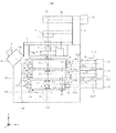
- FIG. 1 is a schematic side view illustrating a configuration of an inverted microscope according to a first embodiment of the present invention
- FIG. 2 is a side view illustrating a state where two optical devices are installed in the inverted microscope illustrated in FIG. 1 ;
- FIG. 3 is a front elevational view illustrating an optical path splitting/switching device illustrated in FIG. 1 ;
- FIG. 4 is a side view illustrating the optical path splitting/switching device illustrated in FIG. 1 ;
- FIG. 5 is a cross-sectional view taken along line A-A of FIG. 2 ;
- FIG. 6 is a side view illustrating an optical path splitting/switching device according to Modified Example 1 of the first embodiment
- FIG. 7 is a front elevational view illustrating the optical path splitting/switching device according to Modified Example 1 of the first embodiment
- FIG. 8 is a schematic side view illustrating a configuration of an inverted microscope according to a second embodiment of the present invention.
- FIG. 9 is a cross-sectional view taken along line C-C of FIG. 8 ;
- FIG. 10 is a front elevational view illustrating an optical path splitting/switching device according to Modified Example 2 of the second embodiment
- FIG. 11 is a side view illustrating the optical path splitting/switching device illustrated in FIG. 10 ;
- FIG. 12 is a schematic side view illustrating a configuration of an inverted microscope according to a third embodiment of the present invention.
- FIG. 13 is a cross-sectional view taken along line D 1 -D 1 of FIG. 12 ;
- FIG. 14 is a cross-sectional view taken along line D 2 -D 2 of FIG. 12 .
- FIGS. 1 and 2 are side views illustrating an inverted microscope according to a first embodiment of the present invention.
- the inverted microscope 100 according to the first embodiment is a microscope in which a specimen 1 as an observation object is viewed from underneath.
- a plurality of optical devices each of which has a function of branching and switching an optical path or a function of selecting of a specified wavelength component, is detachably arranged between an objective lens and an imaging lens.
- FIG. 1 illustrates a state where three optical devices are arranged in the inverted microscope 100
- FIG. 2 illustrates a state where two optical devices are arranged in the inverted microscope 100 .
- the side left side in FIG.
- FIGS. 1 and 2 are the right sides of the inverted microscope 100 .
- the inverted microscope 100 is configured to include a microscope main body 10 , a stage 2 supported by the microscope main body 10 , an objective lens 3 used for observing the specimen 1 mounted on the stage 2 , a revolver 4 which is disposed under the stage 2 to hold the objective lens 3 , and a focusing device 5 installed in the microscope main body 10 .
- the revolver 4 can hold one or more objective lenses 3 and rotate to arrange one objective lens 3 on an optical path of an illumination light beam.
- the focusing device 5 is configured to move the revolver 4 upwards or downwards along an optical axis La of the objective lens 3 arranged on the optical path to adjust the focus of the objective lens 3 to the specimen 1 .
- a transmitted-light-illumination supporting post 6 is attached to the upper rear side of the microscope main body 10 .
- a transmitted-light-illumination light source 7 a , a light transmission projection device 7 b , and a condenser lens 7 c constituting a transmitted-light-illumination optical system are installed in the transmitted-light-illumination supporting post 6 .
- a mirror 7 d is installed in the light transmission projection device 7 b , so that an illumination light beam emitted from the transmitted-light-illumination light source 7 a passes through the light transmission projection device 7 b and is reflected by the mirror 7 d to be incident on the condenser lens 7 c.
- an imaging lens 11 a which forms an image of the observation light beam from the objective lens 3 , a mirror 11 b which bends the optical path of the observation light beam, and a relay lens 11 c are disposed as an observation optical system.
- the imaging lens 11 a is arranged at a position where an optical axis Lb of the imaging lens 11 a is shifted from the optical axis La of the objective lens by ⁇ 3 in a direction perpendicular to the optical axis La.
- the shift amount ⁇ 3 is set to be a half of a total shift amount ⁇ .
- the relay lens 11 c is arranged such that an optical axis of the relay lens 11 c is aligned with the optical axis of the imaging lens 11 a.
- a lens barrel 8 including the imaging lens therein and an ocular piece 9 including the ocular lens therein are assembled at the upper front side of the microscope main body 10 .
- a user can observe an observation image of the specimen 1 by peeping into the ocular piece 9 .
- a space 15 is formed in a central portion of the microscope main body 10 , that is, between the revolver 4 and the imaging lens 11 a by digging out from the side of the one surface of the microscope main body 10 .
- the space 15 is an area for installing a plurality of optical devices.
- the space 15 is formed on the right-side (front side of FIGS. 1 and 2 ) surface of the microscope main body 10 as seen from the front side of the microscope main body 10 .
- the opposite-side surface of the microscope main body 10 is formed to be flat.
- a through-hole 15 a through which the illumination light beam and the observation light beam can pass is formed in the upper portion of the space 15 .
- a plurality of installation units 13 (three installation units in FIGS. 1 and 2 ) for installing the plurality of optical devices in the microscope main body 10 are provided.
- Each of the installation units 13 includes a slide groove 13 a (in the right side in the figure) and a slide groove 13 b (in the left side in the figure) which have the same U-shape.
- optical path splitting/switching devices 20 each having the optical path splitting mirror 21 are installed in the installation units 13 .
- the optical path splitting mirror 21 is, for example, a half mirror which reflects the one half of an incident light beam and transmits the other half thereof.
- a dichroic mirror which reflects a specified wavelength component of an incident light beam and transmits the remaining wavelength component thereof may be used as the optical path splitting mirror 21 .
- Three through-holes 12 a which penetrate the outer side of the microscope main body 10 and the space 15 are arranged side by side in a vertical direction on the rear surface of the microscope main body 10 .
- An attachment portion 12 is formed at the end portion of the each through-hole 12 a .
- Incident-light-illumination projection devices (light transmission tubes) 31 a , 31 b , and 31 c where incident-light-illumination light sources 30 are assembled are attached to the attachment portions 12 .
- Each illumination light beam emitted from each of the incident-light-illumination light sources 30 passes through each through-hole 12 a through each of the incident-light-illumination projection devices 31 a , 31 b , and 31 c to be incident on each optical path splitting/switching device 20 .
- the incident-light-illumination light sources 30 the incident-light-illumination projection devices (light transmission tubes) 31 a , 31 b , and 31 c , and the optical path splitting/switching devices 20 constitute an incident-light-illumination optical system.
- FIG. 3 is a front elevational view illustrating the optical path splitting/switching device 20 ;
- FIG. 4 is a side view illustrating the optical path splitting/switching device 20 ;
- FIG. 5 is a cross-sectional view taken along line A-A of FIG. 2 .
- a portion of the vicinity of a penetration screw hole 14 a is also illustrated in the cross section.
- the inverted microscope 100 is arranged such that the front side of the optical path splitting/switching device 20 illustrated in FIG. 3 is directed to the right-side surface of the inverted microscope 100 .
- protrusions 22 and 23 which can be inserted into the slide grooves 13 a and 13 b , respectively, are formed in the both sides of a casing 20 a of the optical path splitting/switching device 20 .
- An aperture 24 for introducing the transmitted-light-illumination light beam is formed on the one side surface (rear-side surface when the optical path splitting/switching device 20 is installed in the microscope main body 10 ) of the optical path splitting/switching device 20 . Therefore, in order to secure the aperture 24 , the protrusion 22 of the side of the aperture 24 is formed in a shape where a portion thereof is notched.
- Apertures 24 a and 24 b for passing the illumination light beam and the observation light beam are formed on the upper and lower surfaces of the optical path splitting/switching device 20 , respectively.
- a lower surface 221 of the protrusion 22 is formed as a plane parallel to the lower surface of the optical path splitting/switching device 20 .
- the one end portion of the upper surface of the protrusion 22 is formed as a chamfered arced surface 222 so that the cross section thereof has an arc shape.
- the other end portion of the upper surface of the protrusion 22 is formed as a chamfered inclined surface 223 so that the cross section thereof has a straight line shape.
- An end surface 224 of the rear side of the protrusion 22 is formed as a plane perpendicular to the lower surface 221 .
- a lower surface 231 , an arced surface 232 , an inclined surface 233 , and an end surface 234 are formed in the protrusion 23 so as to have a mirror symmetry with those of the protrusion 22 .
- a bottom surface 131 of the slide groove 13 a provided in the microscope main body 10 is an abutting reference surface on which the lower surface 221 of the protrusion 22 is abutted.
- the back-side end portion of the slide groove 13 a in the slide insertion direction is formed to be an inclined surface.
- the inclined surface 132 is an abutting reference surface on which the arced surface 222 of the protrusion 22 is abutted.
- An end surface 133 of the slide groove 13 a is an abutting reference surface on which the end surface 224 (refer to FIG. 3 ) of the protrusion 22 is abutted.
- the penetration screw hole 14 a into which a screw 14 is screwed is formed in the vicinity of the entrance of the slide groove 13 a.
- the slide groove 13 b into which the protrusion 23 is slidably inserted is configured to include a bottom surface 134 on which the lower surface 231 of the protrusion 23 is abutted, an inclined surface 135 on which the arced surface 232 of the protrusion 23 is abutted, and an end surface 136 on which the end surface 234 of the protrusion 23 is abutted.
- the penetration screw hole 14 a is formed in the vicinity of the slide groove 13 b (refer to FIG. 2 ).
- the protrusions 22 and 23 of the optical path splitting/switching device 20 are inserted into the slide grooves 13 a and 13 b ; the lower surfaces 221 and 231 , the arced surfaces 222 and 232 , and the end surfaces 224 and 234 of the protrusions 22 and 23 are abutted on the bottom surfaces 131 and 134 , the inclined surfaces 132 and 135 , and the end surfaces 133 and 136 of the slide grooves 13 a and 13 b .
- the position of the optical path splitting/switching device 20 in the three-axis (X, Y, and Z axis) directions with respect to the microscope main body 10 is aligned.
- the screw 14 is screwed into the penetration screw hole 14 a to be abutted and pressed on the inclined surfaces 223 and 233 . Therefore, the optical path splitting/switching device 20 is forced in the slide insertion direction and the downward direction so as to be fixed in the microscope main body 10 .
- the arced surfaces 222 and 232 are pressingly attached to the inclined surfaces 132 and 135 , uplifting of the protrusions 22 and 23 from the bottom surfaces 131 and 134 of the slide grooves 13 a and 13 b is also prevented.
- the installation units 13 are arranged at the positions shifted from each other in the direction perpendicular to the optical axis La of the objective lens 3 . More specifically, the installation unit 13 of the upper stage which is closest to the objective lens 3 is formed at the position where the center thereof is coincident with the optical axis La. The installation unit 13 of the middle stage is formed at the position where the end surfaces 133 and 136 are shifted with respect to the installation unit 13 of the upper stage by ⁇ 1 in the left direction of the figure. The installation unit 13 of the lower stage is formed at the position where the end surfaces 133 and 136 are shifted with respect to the installation unit 13 of the upper stage by ⁇ 2 ( ⁇ 2> ⁇ 1) in the left direction of the figure.
- the optical paths of the incident-light-illumination optical system of the respective stages are shifted from each other. More specifically, in the incident-light-illumination optical system of the upper stage, the reflection position (intersection point between the reflecting plane and the optical axis Lc 1 ) of the illumination light beam on the optical path splitting mirror 21 exists on the optical axis La of the objective lens 3 .
- the reflection position (intersection point between the reflecting plane and the optical axis Lc 2 ) of the illumination light beam on the optical path splitting mirror 21 is separated by a shift amount ⁇ 1 from the optical axis La of the objective lens 3 along the optical axis Lc 2 of the illumination light beam.
- the reflection position (intersection point between the reflecting plane and the optical axis Lc 3 ) of the transmitted-light-illumination light beam on the optical path splitting mirror 21 is separated by a shift amount ⁇ 2 from the optical axis La of the objective lens 3 along the optical axis Lc 3 of the illumination light beam.
- the shift amount ⁇ 1 corresponds to an amount of shift of the optical path due to diffraction of the observation light beam when the observation light beam passes through the optical path splitting mirror 21 of the upper stage.
- an illumination light beam (transmitted-light-illumination light beam) is emitted from the transmitted-light-illumination light source 7 a provided above the microscope main body 10 .
- the optical path of the illumination light beam is bent by the mirror 7 d in the light transmission projection device 7 b , and the illumination light beam is condensed on a pupil surface of the condenser lens 7 c . After that, the illumination light beam as a parallel light beam is irradiated on the specimen 1 to transmit the specimen 1 .
- illumination light beams (transmitted-light-illumination light beams) are emitted from the incident-light-illumination light sources 30 of the upper, middle, and lower stages which are installed in the rear surface of the microscope main body 10 .
- the illumination light beams are introduced through the incident-light-illumination projection devices 31 a , 31 b , and 31 c and the through-holes 12 a from the apertures 24 to the optical path splitting/switching devices 20 .
- the optical paths of the illumination light beams are bent upward by the optical path splitting mirrors 21 of the respective stages.
- the illumination light beam is reflected to the direction of the optical axis La by the optical path splitting mirror 21 to be incident on the objective lens 3 .
- the reflection position of the illumination light beam on the optical path splitting mirror 21 is shifted by ⁇ 1 from the optical axis La. Therefore, after the illumination light beam is reflected to the direction parallel to the optical axis La, the illumination light beam is incident on the optical path splitting mirror 21 of the upper stage at the position separated by ⁇ 1 from the optical axis La.
- the optical path is shifted due to diffraction of the illumination light beam when the illumination light beam passes through the optical path splitting mirror 21 of the upper stage, so that the illumination light beam is incident through the optical axis La on the objective lens 3 .
- the reflection position of the illumination light beam on the optical path splitting mirror 21 is shifted by ⁇ 2 from the optical axis La. Therefore, after the illumination light beam is reflected to the direction parallel to the optical axis La, the illumination light beam is incident on the optical path splitting mirror 21 of the middle stage at the position separated by ⁇ 2 from the optical axis La.
- the optical path of the illumination light beam is shifted due to diffraction of the illumination light beam when the illumination light beam passes through the optical path splitting mirror 21 of the upper stage, so that the illumination light beam is incident through the optical axis La on the objective lens 3 .
- the illumination light beams from the respective stages can be combined on the optical axis La just before the incidence on the objective lens 3 .
- the illumination light beam incident on the objective lens 3 is irradiated on the specimen 1 to be reflected by the specimen 1 .
- the light beam (observation light beam) which transmits the specimen 1 or is reflected by the specimen 1 passes through the objective lens 3 to be converted into a parallel light beam having the optical axis La as a central axis.
- the parallel light beam sequentially passes through the optical path splitting mirrors 21 of the upper, middle, and lower stages.
- the observation light beam is refracted every time that the observation light beam passes through each optical path splitting mirror 21 , and as a result, the optical path is parallel to the optical axis La and is shifted to the position separated by a shift amount ⁇ from the optical axis La.
- the shift amount ⁇ 3 ⁇ 1.
- the observation light beam is incident on the imaging lens 11 a at the position separated by the shift amount ⁇ from the optical axis La.
- the observation light beam is condensed by the imaging lens 11 a , and the optical path thereof can be changed by the mirror 11 b .
- the observation light beam is converted into a parallel light beam again by the relay lens 11 c , the parallel light beam is incident through the mirror 11 b into the lens barrel 8 .
- the observation light beam is formed into an image by an imaging lens to be emitted through the ocular piece 9 from the inverted microscope 100 . Therefore, a user can observe an observation image of the specimen 1 .
- each optical path splitting/switching device 20 is fixed by using the screw 14 , the optical path splitting/switching device 20 can be attached and detached individually and easily. Therefore, the case where some of the optical path splitting/switching devices 20 are removed and the number of to-be-used incident-light-illumination optical systems is changed will be described.
- the incident-light-illumination optical system of the upper stage is used with priority. For example, in the case where only one incident-light-illumination optical system is used, the optical path splitting/switching device 20 is installed only in the upper stage. In addition, in the case where two incident-light-illumination optical systems are used, the optical path splitting/switching devices 20 are installed in the upper and middle stages. FIG. 2 illustrates the latter state.
- the illumination light beams from the incident-light-illumination light sources 30 of the upper and middle stages are combined on the optical axis La to be incident on the objective lens 3 .
- the observation light beam which passes through the objective lens 3 passes through the optical path splitting mirrors 21 of the upper and middle stages, so that the observation light beam is incident on the imaging lens 11 a in the state where the observation light beam is shifted by ⁇ 2 with respect to the optical axis La.
- the optical axis (hereinafter, referred to as an observation optical axis) of the observation light beam is shifted by
- the inter-axis distance between the observation optical axis and the optical axis Lb is shorter than the inter-axis distance ( ⁇ 3) of the case where the optical path splitting/switching device 20 is also installed in the lower stage (refer to FIG. 1 ).
- the inter-axis distance between the observation optical axis and the optical axis Lb is
- the inter-axis distance between the observation optical axis (that is, the optical axis La) and the optical axis Lb is ⁇ 3.
- the installation units 13 having the same shape with each other for installation of the optical path splitting/switching devices 20 constituting a portion of the incident-light-illumination optical systems are independently arranged between the revolver 4 and the imaging lens 11 a , the optical path splitting/switching devices 20 can be attached to and detached from the microscope main body 10 individually and easily without a change in design of the microscope main body 10 . Therefore, replacement of the installation of the incident-light-illumination optical system or changing of the number of installation stages can be easily performed, so that it is possible to improve expandability of the inverted microscope 100 .
- the optical path splitting/switching device 20 is installed in the microscope main body 10 in such a manner where the protrusions 22 and 23 of the optical path splitting/switching device 20 of each stage are inserted into the slide grooves 13 a and 13 b , the position of the optical path splitting/switching device 20 can be easily determined.
- the fixing of the optical path splitting/switching device 20 is performed by using the screw 14 , the installation and removal of the optical path splitting/switching device 20 can be simply performed.
- the space 15 is prepared in one side surface of the microscope main body 10 and the installation units 13 is prepared on the inner wall of the space 15 , the attachment and detachment of the optical path splitting/switching device 20 can be performed from the one side of the microscope main body 10 . Therefore, it is possible to improve operability of the inverted microscope 100 .
- the central axis of the optical path splitting/switching device 20 is shifted by a specified amount in the direction perpendicular to the optical axis La of the objective lens 3 , the optical path of the illumination light beam from the incident-light-illumination optical system of each stage can be shifted on the optical axis La of the objective lens 3 just before incidence on the objective lens 3 . Therefore, it is possible to prevent deflection of the illumination on the specimen 1 .
- the position of the optical axis Lb of the imaging lens 11 a is also shifted according to the shift amount of the optical path splitting/switching device 20 installed in the each stage with respect to the optical axis La, the inter-axis distance between the observation optical axis and the optical axis Lb can be suppressed to be small. Therefore, it is possible to configure the microscope main body 10 with a compact size without an increase in the effective diameters of the imaging lens 11 a and the optical members of the following stages.
- the slide grooves 13 a and 13 b are formed to have a “U”-shaped side surface
- the side surface shape of the slide grooves 13 a and 13 b is not limited thereto.
- the slide grooves 13 a and 13 b may have a shape of an ant.
- any unit other than the screw 14 may be used as a fixing unit for fixing the optical path splitting/switching device 20 to the microscope main body 10 .
- the retraction fixing using a screw or the like may be performed.
- the shift amount ⁇ 3 (distance between the optical axis La and the optical axis Lb) of the optical axis Lb of the imaging lens 11 a with respect to the optical axis La of the objective lens 3 is not necessarily limited to the half of the total shift amount ⁇ occurring due to the passing of the observation light beam from the objective lens 3 through the optical path splitting mirrors 21 of the upper, middle, and lower stages.
- the shift amount ⁇ 3 may be ⁇ /2 or less.
- the number of optical devices which can be installed in the microscope main body 10 is not particularly limited if the number is two or more.
- FIG. 6 is a side view illustrating an optical path splitting/switching device of Modified Example 1.
- FIG. 7 is a front elevational view illustrating the optical path splitting/switching device illustrated in FIG. 6 and illustrates a cross section taken along line B-B of FIG. 6 .
- the optical path splitting/switching device 20 A is configured to include the casing 20 a , and protrusions 22 a and 23 a are provided on the both side surfaces thereof.
- the shape of the protrusion 22 a is the same as that of the first embodiment.
- the outer shape of the protrusion 23 a is the same as that of the protrusion 23 of the first embodiment, the protrusion 23 a is different from the protrusion 23 of the first embodiment in that an elastic member is incorporated into the protrusion 23 a.
- An aperture is provided on an end surface 235 of the protrusion 23 a , and a ball plunger 236 as an elastic member can be assembled into the aperture.
- An end portion of the ball plunger 236 is slightly protruded outwards from the end surface 235 .
- the end surface 224 of the side of the protrusion 22 a can be abutted on the end surface 133 of the slide groove 13 a . Therefore, the position of the optical path splitting/switching device 20 A can be performed accurately and easily.
- FIG. 8 is a schematic side view illustrating an inverted microscope according to a second embodiment of the present invention.
- the inverted microscope 200 according to the second embodiment is configured to include a microscope main body 10 a .
- the overall shape and structure of the microscope main body 10 a are the same as those of the microscope main body 10 of the first embodiment, and the structure of an installation unit 13 ′ where an optical device is installed in the microscope main body is different from that of the first embodiment.
- FIG. 8 illustrates a case where an optical path splitting/switching device 20 B is installed in the upper stage; an optical path splitting/switching device 20 C is installed in the middle stage; and no optical device is installed in the lower stage.
- the structures of the optical path splitting/switching devices 20 B and 20 C are the same as that of the optical path splitting/switching device 20 described in the first embodiment, and the optical path splitting/switching devices 20 B and 20 C are different from the optical path splitting/switching device 20 in terms of the thickness of optical path splitting mirrors 21 a and 21 b embedded in the optical path splitting/switching devices 20 B and 20 C.
- a space 16 is provided in a central portion of the microscope main body 10 a , that is, between the revolver 4 and the imaging lens 11 a by digging out from the side of one surface of the microscope main body 10 a .
- the space 16 is an area for installing a plurality of optical devices (optical path splitting/switching devices 20 B and 20 C and the like).
- a through-hole 16 a which an illumination light beam and an observation light beam can pass through is provided in the upper portion of the space 16 .
- Each of the installation units 13 ′ includes a slide groove 13 c (in the right side of the figure) and a slide groove 13 d (in the left side of the figure) which are formed in the same U-shape.
- the arrangements of the installation units 13 ′ in the direction perpendicular to the optical axis La of the objective lens 3 are the same. Therefore, the distance D between the end surfaces 133 and 136 of the slide grooves 13 c and 13 d of each stage is also the same as those of the other stages.
- the distance D is larger than d 1 between the two ends of the protrusions 22 and 23 formed in the optical path splitting/switching devices 20 B and 20 C.
- a spacer 40 a is installed in the slide groove 13 c of the upper stage; and a spacer 40 b of which width (length in the same direction as that of the interval D) is different from the width of the spacer 40 a is installed in the slide groove 13 c of the middle stage.
- the width of the spacer 40 a of the upper stage is defined by L 1 ; and the width of the spacer 40 b of the middle stage is defined by L 2 .
- FIG. 9 is a cross-sectional view taken along line C-C of FIG. 8 and is a diagram for describing a structure of the spacer 40 a .
- the spacer 40 a is configured to include an insert portion 401 which is inserted into the slide groove 13 c and a fixed portion 402 which is fixed to the microscope main body 10 a .
- a through-hole 403 is formed in the fixed portion 402 .
- a screw hole 137 is formed in the end surface in the vicinity of the entrance of the slide groove 13 c on which the fixed portion 402 abuts.
- the length (depth of insertion into the slide groove 13 c ) of the insert portion 401 in the slide insertion direction is defined by the length of at least a portion of the end surface 224 of the protrusion 22 abutting on the insert portion 401 when the protrusion 22 of the optical path splitting/switching device 20 B is inserted into the slide groove 13 c .
- a side surface 401 a (refer to FIG. 8 ) of the insert portion 401 abutting on the end surface 224 is the abutting reference surface of the optical path splitting/switching device 20 B.
- the structure of the spacer 40 b is also the same as that of the spacer 40 a , and thus, the description thereof is not provided.
- the spacer 40 a is attached to the side of the slide groove 13 c .
- the protrusions 22 and 23 are inserted into the slide grooves 13 c and 13 d , so that the end surface 224 of the protrusion 22 is abutted on the spacer 40 a .
- the screw 14 is screwed into the penetration screw hole 14 a to be abutted on the inclined surfaces 223 and 233 (refer to FIGS. 3 and 5 ) of the protrusions 22 and 23 , so that the optical path splitting/switching device 20 B is fixed.
- the optical path splitting/switching device 20 C is installed in the installation unit 13 ′ of the middle stage.
- a width L 1 of the spacer 40 a attached to the slide groove 13 c of the upper stage is determined so that the reflection position of the illumination light beam emitted from the incident-light-illumination light source 30 on the optical path splitting mirror 21 a is coincident with the optical axis La of the objective lens 3 .
- a width L 2 of the spacer 40 b attached to the slide groove 13 c of the middle stage is determined based on a shift amount ⁇ 4 of the shifting of the optical path from the optical axis La due to diffraction when the illumination light beam and the observation light beam pass through the optical path splitting mirror 21 a of the upper stage.
- the width of the spacer attached to the slide groove 13 c of the lower stage is determined based on a total shift amount ⁇ 5 of the shifting of the optical path from the optical axis La due to diffraction when the light beam passes through the optical path splitting mirrors 21 a and 21 b of the upper and middle stages.
- the abutting reference surface for determining the positions of the optical path splitting/switching devices 20 B and 20 C is shifted by installing the spacers 40 a and 40 b having different widths to the slide groove 13 c .
- the shapes and positions of the installation units 13 ′ can be aligned in the upper, middle, and lower stages, it is possible to simplify the design of the microscope main body 10 a .
- the positions of the optical path splitting/switching devices 20 B and 20 C in the direction perpendicular to the optical axis La can be easily determined by appropriately selecting the spacers 40 a and 40 b , the configuration of the microscope main body 10 a is simplified, so that it is possible to manufacture the microscope main body 10 a at a low price.
- the fixing of the spacers 40 a and 40 b to the slide groove 13 c is released by unfastening the set screw 41 , the spacers 40 a and 40 b can be easily replaced. Therefore, the positions of the optical path splitting/switching devices 20 B and 20 C can be separately adjusted by optically appropriate amounts. Accordingly, change in the installation positions of the optical path splitting/switching devices 20 B and 20 C or replacement with different types of optical devices having different shift amounts of the optical path can be easily performed. In other words, it is possible to further improve expandability of the inverted microscope 200 while securing necessary optical performance.
- FIG. 10 is a front elevational view illustrating an optical path splitting/switching device according to Modified Example 2.
- FIG. 11 is a side view illustrating the optical path splitting/switching device illustrated in FIG. 10 .
- the optical path splitting/switching device illustrated in FIG. 8 is to be installed on the inverted microscope 200 , although the spacer is prepared in the slide groove 13 c in the second embodiment, a spacer may be provided on the side of the optical path splitting/switching device.
- the optical path splitting/switching device 20 D is configured to include a casing 20 a , and protrusions 22 d and 23 d are provided on the both side surfaces thereof.
- the shape of the protrusion 23 d is the same as that of the protrusion 23 (refer to FIG. 3 ) of the first embodiment.
- the outer shape of the protrusion 22 d is the same as that of the protrusion 22 of the first embodiment, the protrusion 22 d is different from the protrusion 22 of the first embodiment in that a screw hole 226 for installing a spacer 42 is provided on an end surface 225 .
- a counterbore hole 421 is provided in the spacer 42 .
- a set screw 422 is arranged in the counterbore hole 421 and is screwed into the screw hole 226 , so that the spacer 42 is detachably fixed to the protrusion 22 d.
- the spacer 42 is detachably installed on the protrusion 22 d , so that a distance d 2 from the end surface of the spacer 42 , that is, the abutting surface which is abutted on the end surface 133 of the slide groove 13 c to the central axis of the optical path splitting mirror 21 can be changed. Therefore, the position of the optical path splitting/switching device 20 D in the direction perpendicular to the optical axis La can be easily determined.
- FIG. 12 is a schematic side view illustrating an inverted microscope according to a third embodiment of the present invention.
- the inverted microscope 300 according to the third embodiment has a feature in that an installation position of an optical device installed in the microscope main body is automatically detected.
- the inverted microscope 300 is configured to include a microscope main body 10 b .
- the overall shape and structure of the microscope main body 10 b are the same as those of the microscope main body 10 of the first embodiment, and the number of optical devices which can be installed in a space 17 which is prepared for installation of a plurality of optical devices (optical path splitting/switching devices 20 E and the like) is different from that of the first embodiment.
- a through-hole 17 a which an illumination light beam and an observation light beam can pass through is provided in the upper portion of the space 17 .
- Plural stages (two stages in FIG. 12 ) of installation units 13 for installing the optical devices in the microscope main body 10 b are provided on the inner wall of the space 17 .
- the structures and arrangements (the shift amounts in the direction perpendicular to the optical axis La) of the installation units 13 of the respective stages are the same as those of the first embodiment.
- a control unit 50 is connected through a cable 253 to the microscope main body 10 b.
- Each optical path splitting/switching device 20 E includes different types of optical path splitting mirrors 21 c and 21 d , a support unit 21 e which rotatably supports the optical path splitting mirrors 21 c and 21 d , and a motor M which rotates the support unit 21 e .
- the motor M is connected through the cable 253 to the control unit 50 , so that the motor M is operated under the control of the control unit 50 .
- the optical path splitting mirrors 21 c and 21 d are, for example, dichroic mirrors which reflect and transmit light beams having different wavelengths. Therefore, the shift amounts of the shifting of the optical path in the direction perpendicular to the optical axis La of the objective lens 3 are different between the optical path splitting mirrors 21 c and 21 d due to diffraction when the light beams pass through the optical path splitting mirrors 21 c and 21 d .
- the support unit 21 e and the optical path splitting mirrors 21 c and 21 d are rotated through ⁇ -axis rotation. Therefore, the mirror arranged on the optical axis La of the objective lens 3 is switched.
- FIG. 13 is a cross-sectional view taken along line D 1 -D 1 of FIG. 12 and illustrates a configuration in the vicinity of the side surface of the optical path splitting/switching device 20 E of the upper stage.
- FIG. 14 is a cross-sectional view taken along line D 2 -D 2 of FIG. 12 and illustrates a configuration in the vicinity of the side surface of the optical path splitting/switching device 20 E of the lower stage.
- an aperture 201 is formed in a casing 20 b of the optical path splitting/switching device 20 E.
- a detecting unit 25 is provided at the position facing the aperture 201 in the casing 20 b .
- the detecting unit 25 is a so-called switch member and is fixed to the casing 20 b through a fixed portion 251 in the upper side of the figure.
- a detecting member 252 is formed in the side of the detecting unit 25 facing the aperture 201 , and the cable 253 is connected to the opposite side thereof.
- An electric circuit is installed inside the detecting unit 25 , and by pressing the detecting member 252 , the electric circuit is opened or closed.
- the detecting unit 25 is connected through the cable 253 to the control unit 50 .
- a projected portion 101 as a to-be-detected portion with respect to the detecting unit 25 is provided on the wall surface (microscope main body 10 b ) of the end portion of the optical path splitting/switching device 20 E of the lower stage in the slide insertion direction.
- the projected portion 101 is smaller than the aperture 201 , and the length thereof is formed so that the projected portion 101 can press on the end surface of the detecting member 252 when the optical path splitting/switching device 20 E is to be installed in the installation unit 13 (refer to FIG. 1 ).
- the detecting unit 25 and the projected portion 101 constitute a detecting device (detecting means) for detecting the installation position of the optical path splitting/switching device 20 E.
- FIG. 14 illustrates the state where the projected portion 101 presses the detecting member 252 .
- the control unit 50 receives the electrical signal to identify which stage of the microscope main body 10 b the optical path splitting/switching device 20 E is installed in.
- the control unit 50 transmits a control signal for controlling the motor M through the cable 253 according to the installation stage of the optical path splitting/switching device 20 E, so that the optical path splitting mirrors 21 c and 21 d embedded in the desired optical path splitting/switching device 20 E are switched.
- the stages where automatic detection of the optical path splitting/switching devices 20 E are installed can be individually performed to identify the respective optical path splitting/switching devices 20 E, so that the optical path splitting/switching devices 20 E can be individually controlled.
- the detecting unit 25 and the projected portion 101 may be provided in parallel for each stage. In this case, even in the case where three stages or more of optical devices are installed in the microscope main body, the same control can be performed.
- a contact type switch is used as the detecting unit 25
- the type of the switch is not limited thereto.
- a non-contact type optical or magnetic sensor may be used.
- any of the optical devices can be easily attached to and detached from the microscope main body without a change in design of the microscope main body.
- a plurality of abutting reference surfaces of the plurality of installation units is shifted from one another in a direction perpendicular to the optical axis of the objective lens, the optical axes of the light beams passing through the optical devices are also shifted in the same manner, so that necessary and sufficient optical performance can be achieved according to the positions of the optical devices and the number of the optical devices in the inverted microscope.
Landscapes
- Physics & Mathematics (AREA)
- Chemical & Material Sciences (AREA)
- Analytical Chemistry (AREA)
- General Physics & Mathematics (AREA)
- Optics & Photonics (AREA)
- Microscoopes, Condenser (AREA)
Abstract
Description
Claims (3)
Applications Claiming Priority (2)
| Application Number | Priority Date | Filing Date | Title |
|---|---|---|---|
| JP2012082611A JP5911354B2 (en) | 2012-03-30 | 2012-03-30 | Inverted microscope |
| JP2012-082611 | 2012-03-30 |
Publications (2)
| Publication Number | Publication Date |
|---|---|
| US20130258457A1 US20130258457A1 (en) | 2013-10-03 |
| US9494780B2 true US9494780B2 (en) | 2016-11-15 |
Family
ID=47997239
Family Applications (1)
| Application Number | Title | Priority Date | Filing Date |
|---|---|---|---|
| US13/851,921 Active 2034-04-21 US9494780B2 (en) | 2012-03-30 | 2013-03-27 | Inverted microscope |
Country Status (3)
| Country | Link |
|---|---|
| US (1) | US9494780B2 (en) |
| EP (1) | EP2645145B1 (en) |
| JP (1) | JP5911354B2 (en) |
Citations (15)
| Publication number | Priority date | Publication date | Assignee | Title |
|---|---|---|---|---|
| US4337991A (en) * | 1980-09-29 | 1982-07-06 | Le Materiel Biomedical | Light microscope with a plurality of slideways |
| US5270855A (en) * | 1990-11-19 | 1993-12-14 | Olympus Optical Co., Ltd. | Microscope having a focus-adjusting mechanism |
| US5535052A (en) * | 1992-07-24 | 1996-07-09 | Carl-Zeiss-Stiftung | Laser microscope |
| JPH1138326A (en) | 1997-07-17 | 1999-02-12 | Nikon Corp | Inverted microscope |
| JPH1172715A (en) | 1997-08-27 | 1999-03-16 | Nikon Corp | Inverted microscope |
| JPH11344675A (en) | 1998-05-29 | 1999-12-14 | Nikon Corp | Inverted microscope |
| JP2002267940A (en) | 2001-03-09 | 2002-09-18 | Olympus Optical Co Ltd | Inverted microscope system |
| US6813071B2 (en) * | 2001-03-23 | 2004-11-02 | Olympus Optical Co., Ltd. | Inverted microscope |
| US6865021B2 (en) * | 2001-09-27 | 2005-03-08 | Olympus Optical Co., Ltd. | Incident illumination unit and microscope to which incident illumination unit is applied |
| US20060066942A1 (en) * | 2004-09-27 | 2006-03-30 | Olympus Corporation | Inverted microscope |
| US20070146872A1 (en) * | 2003-11-07 | 2007-06-28 | Carl Zeiss Jena Gmbh | Invertible light-optical microscope |
| JP2010532468A (en) | 2007-07-05 | 2010-10-07 | ホフマン、クルト | Apparatus and method for measuring static and dynamic scattering light at low volume |
| WO2011149090A1 (en) | 2010-05-28 | 2011-12-01 | オリンパス株式会社 | Inverted microscope |
| JP2013114004A (en) | 2011-11-28 | 2013-06-10 | Olympus Corp | Microscope |
| US20130286473A1 (en) * | 2012-04-27 | 2013-10-31 | Olympus Corporation | Inverted microscope |
-
2012
- 2012-03-30 JP JP2012082611A patent/JP5911354B2/en active Active
-
2013
- 2013-03-27 US US13/851,921 patent/US9494780B2/en active Active
- 2013-03-28 EP EP13161635.1A patent/EP2645145B1/en active Active
Patent Citations (23)
| Publication number | Priority date | Publication date | Assignee | Title |
|---|---|---|---|---|
| US4337991A (en) * | 1980-09-29 | 1982-07-06 | Le Materiel Biomedical | Light microscope with a plurality of slideways |
| US5270855A (en) * | 1990-11-19 | 1993-12-14 | Olympus Optical Co., Ltd. | Microscope having a focus-adjusting mechanism |
| US5535052A (en) * | 1992-07-24 | 1996-07-09 | Carl-Zeiss-Stiftung | Laser microscope |
| JPH1138326A (en) | 1997-07-17 | 1999-02-12 | Nikon Corp | Inverted microscope |
| JPH1172715A (en) | 1997-08-27 | 1999-03-16 | Nikon Corp | Inverted microscope |
| US6239905B1 (en) | 1997-08-27 | 2001-05-29 | Nikon Corporation | Inverted microscope |
| JPH11344675A (en) | 1998-05-29 | 1999-12-14 | Nikon Corp | Inverted microscope |
| US6160662A (en) | 1998-05-29 | 2000-12-12 | Nikon Corporation | Inverted microscope having a variable stage position |
| JP2002267940A (en) | 2001-03-09 | 2002-09-18 | Olympus Optical Co Ltd | Inverted microscope system |
| US20020131165A1 (en) | 2001-03-09 | 2002-09-19 | Olympus Optical Co., Ltd. | Inverted microscope system |
| US6813071B2 (en) * | 2001-03-23 | 2004-11-02 | Olympus Optical Co., Ltd. | Inverted microscope |
| US6865021B2 (en) * | 2001-09-27 | 2005-03-08 | Olympus Optical Co., Ltd. | Incident illumination unit and microscope to which incident illumination unit is applied |
| US20070146872A1 (en) * | 2003-11-07 | 2007-06-28 | Carl Zeiss Jena Gmbh | Invertible light-optical microscope |
| US20060066942A1 (en) * | 2004-09-27 | 2006-03-30 | Olympus Corporation | Inverted microscope |
| JP2006091723A (en) | 2004-09-27 | 2006-04-06 | Olympus Corp | Inverted microscope |
| JP2010532468A (en) | 2007-07-05 | 2010-10-07 | ホフマン、クルト | Apparatus and method for measuring static and dynamic scattering light at low volume |
| US20100315635A1 (en) | 2007-07-05 | 2010-12-16 | Christoph Janzen | Device and method for measuring static and dynamic scattered light in small volumes |
| WO2011149090A1 (en) | 2010-05-28 | 2011-12-01 | オリンパス株式会社 | Inverted microscope |
| JP2011248245A (en) | 2010-05-28 | 2011-12-08 | Olympus Corp | Inverted microscope |
| US20130075578A1 (en) * | 2010-05-28 | 2013-03-28 | Olympus Corporation | Inverted microscope |
| EP2579086A1 (en) | 2010-05-28 | 2013-04-10 | Olympus Corporation | Inverted microscope |
| JP2013114004A (en) | 2011-11-28 | 2013-06-10 | Olympus Corp | Microscope |
| US20130286473A1 (en) * | 2012-04-27 | 2013-10-31 | Olympus Corporation | Inverted microscope |
Non-Patent Citations (2)
| Title |
|---|
| Extended European Search Report (EESR) dated Jun. 20, 2013 (in English) issued in counterpart European Application No. 13161635.1. |
| Japanese Office Action (and English translation thereof) dated Jan. 19, 2016, issued in counterpart Japanese Application No. 2012-082611. |
Also Published As
| Publication number | Publication date |
|---|---|
| US20130258457A1 (en) | 2013-10-03 |
| EP2645145A1 (en) | 2013-10-02 |
| JP5911354B2 (en) | 2016-04-27 |
| JP2013213854A (en) | 2013-10-17 |
| EP2645145B1 (en) | 2018-11-07 |
Similar Documents
| Publication | Publication Date | Title |
|---|---|---|
| CN102301268B (en) | Imaging optical system, and microscope apparatus and stereo microscope apparatus, having the imaging optical system | |
| JP5623654B2 (en) | Confocal laser scanning microscope | |
| EP1956408B1 (en) | Microscope Iens barrel | |
| US6496307B2 (en) | Confocal scanning microscope | |
| US6313944B2 (en) | Microscope turret assembly and a microscope | |
| US10146037B2 (en) | Microscope | |
| US5714749A (en) | Focus detecting apparatus and microscope apparatus equipped with the foregoing apparatus | |
| US9494780B2 (en) | Inverted microscope | |
| EP2028518B1 (en) | Microscope | |
| JP5959247B2 (en) | microscope | |
| US7436524B2 (en) | Apparatus and method for three-dimensional measurement and program for allowing computer to execute method for three-dimensional measurement | |
| JP5512122B2 (en) | Scanning laser microscope and sub-assembly for non-descanned detection | |
| JPH0593845A (en) | Automatic focus detecting device | |
| US6501540B2 (en) | Surveying instrument having an optical distance meter | |
| JP2016057405A (en) | Multiphoton excitation observation system | |
| JP2000056232A (en) | microscope | |
| US6677568B2 (en) | Surveying instrument having a phase-difference detection type focus detecting device | |
| JP5023934B2 (en) | microscope | |
| JPH1184252A (en) | Automatic focusing microscope | |
| JP6032916B2 (en) | Inverted microscope | |
| JP2017009739A (en) | Microscope and microscope system | |
| JP2007085753A (en) | Apparatus for measuring three-dimensional shape | |
| JP2009216944A (en) | Microscope | |
| JP2009075448A (en) | Light detection unit, microscope device | |
| JP2006154407A (en) | Microscope |
Legal Events
| Date | Code | Title | Description |
|---|---|---|---|
| AS | Assignment |
Owner name: OLYMPUS CORPORATION, JAPAN Free format text: ASSIGNMENT OF ASSIGNORS INTEREST;ASSIGNORS:KITAHARA, AKIHIRO;UTSUGI, HIRONORI;AMANO, YUSUKE;SIGNING DATES FROM 20130318 TO 20130319;REEL/FRAME:030100/0500 |
|
| AS | Assignment |
Owner name: OLYMPUS CORPORATION, JAPAN Free format text: CHANGE OF ADDRESS;ASSIGNOR:OLYMPUS CORPORATION;REEL/FRAME:039665/0302 Effective date: 20160401 |
|
| STCF | Information on status: patent grant |
Free format text: PATENTED CASE |
|
| MAFP | Maintenance fee payment |
Free format text: PAYMENT OF MAINTENANCE FEE, 4TH YEAR, LARGE ENTITY (ORIGINAL EVENT CODE: M1551); ENTITY STATUS OF PATENT OWNER: LARGE ENTITY Year of fee payment: 4 |
|
| AS | Assignment |
Owner name: EVIDENT CORPORATION, JAPAN Free format text: ASSIGNMENT OF ASSIGNORS INTEREST;ASSIGNOR:OLYMPUS CORPORATION;REEL/FRAME:062492/0267 Effective date: 20221024 |
|
| MAFP | Maintenance fee payment |
Free format text: PAYMENT OF MAINTENANCE FEE, 8TH YEAR, LARGE ENTITY (ORIGINAL EVENT CODE: M1552); ENTITY STATUS OF PATENT OWNER: LARGE ENTITY Year of fee payment: 8 |