US9494271B2 - Pipe liner and method of using the same - Google Patents
Pipe liner and method of using the same Download PDFInfo
- Publication number
- US9494271B2 US9494271B2 US13/348,481 US201213348481A US9494271B2 US 9494271 B2 US9494271 B2 US 9494271B2 US 201213348481 A US201213348481 A US 201213348481A US 9494271 B2 US9494271 B2 US 9494271B2
- Authority
- US
- United States
- Prior art keywords
- pipe
- liner
- bladder
- length
- diameter
- Prior art date
- Legal status (The legal status is an assumption and is not a legal conclusion. Google has not performed a legal analysis and makes no representation as to the accuracy of the status listed.)
- Expired - Fee Related, expires
Links
- 238000000034 method Methods 0.000 title claims abstract description 52
- 239000012260 resinous material Substances 0.000 claims abstract description 43
- 239000012530 fluid Substances 0.000 claims abstract description 8
- 239000000463 material Substances 0.000 claims description 8
- 239000011248 coating agent Substances 0.000 claims description 6
- 238000000576 coating method Methods 0.000 claims description 6
- 238000010276 construction Methods 0.000 claims description 2
- 238000003825 pressing Methods 0.000 abstract description 2
- 239000010410 layer Substances 0.000 description 12
- 230000008901 benefit Effects 0.000 description 10
- 230000008439 repair process Effects 0.000 description 4
- 239000011347 resin Substances 0.000 description 4
- 229920005989 resin Polymers 0.000 description 4
- 230000008569 process Effects 0.000 description 3
- 238000009434 installation Methods 0.000 description 2
- 238000004519 manufacturing process Methods 0.000 description 2
- 229920000642 polymer Polymers 0.000 description 2
- XLYOFNOQVPJJNP-UHFFFAOYSA-N water Substances O XLYOFNOQVPJJNP-UHFFFAOYSA-N 0.000 description 2
- 238000007792 addition Methods 0.000 description 1
- 230000006835 compression Effects 0.000 description 1
- 238000007906 compression Methods 0.000 description 1
- 238000005520 cutting process Methods 0.000 description 1
- 230000007812 deficiency Effects 0.000 description 1
- 238000011161 development Methods 0.000 description 1
- 230000018109 developmental process Effects 0.000 description 1
- 239000004744 fabric Substances 0.000 description 1
- 239000007789 gas Substances 0.000 description 1
- 238000003780 insertion Methods 0.000 description 1
- 230000037431 insertion Effects 0.000 description 1
- 230000001788 irregular Effects 0.000 description 1
- 238000012986 modification Methods 0.000 description 1
- 230000004048 modification Effects 0.000 description 1
- 239000003921 oil Substances 0.000 description 1
- 239000010865 sewage Substances 0.000 description 1
- 239000002356 single layer Substances 0.000 description 1
- 238000006467 substitution reaction Methods 0.000 description 1
- 239000004634 thermosetting polymer Substances 0.000 description 1
- 230000007704 transition Effects 0.000 description 1
Images


Classifications
-
- F—MECHANICAL ENGINEERING; LIGHTING; HEATING; WEAPONS; BLASTING
- F16—ENGINEERING ELEMENTS AND UNITS; GENERAL MEASURES FOR PRODUCING AND MAINTAINING EFFECTIVE FUNCTIONING OF MACHINES OR INSTALLATIONS; THERMAL INSULATION IN GENERAL
- F16L—PIPES; JOINTS OR FITTINGS FOR PIPES; SUPPORTS FOR PIPES, CABLES OR PROTECTIVE TUBING; MEANS FOR THERMAL INSULATION IN GENERAL
- F16L55/00—Devices or appurtenances for use in, or in connection with, pipes or pipe systems
- F16L55/16—Devices for covering leaks in pipes or hoses, e.g. hose-menders
- F16L55/162—Devices for covering leaks in pipes or hoses, e.g. hose-menders from inside the pipe
- F16L55/165—Devices for covering leaks in pipes or hoses, e.g. hose-menders from inside the pipe a pipe or flexible liner being inserted in the damaged section
- F16L55/1652—Devices for covering leaks in pipes or hoses, e.g. hose-menders from inside the pipe a pipe or flexible liner being inserted in the damaged section the flexible liner being pulled into the damaged section
- F16L55/1654—Devices for covering leaks in pipes or hoses, e.g. hose-menders from inside the pipe a pipe or flexible liner being inserted in the damaged section the flexible liner being pulled into the damaged section and being inflated
-
- B—PERFORMING OPERATIONS; TRANSPORTING
- B29—WORKING OF PLASTICS; WORKING OF SUBSTANCES IN A PLASTIC STATE IN GENERAL
- B29C—SHAPING OR JOINING OF PLASTICS; SHAPING OF MATERIAL IN A PLASTIC STATE, NOT OTHERWISE PROVIDED FOR; AFTER-TREATMENT OF THE SHAPED PRODUCTS, e.g. REPAIRING
- B29C63/00—Lining or sheathing, i.e. applying preformed layers or sheathings of plastics; Apparatus therefor
- B29C63/26—Lining or sheathing of internal surfaces
- B29C63/34—Lining or sheathing of internal surfaces using tubular layers or sheathings
- B29C63/36—Lining or sheathing of internal surfaces using tubular layers or sheathings being turned inside out
-
- F—MECHANICAL ENGINEERING; LIGHTING; HEATING; WEAPONS; BLASTING
- F16—ENGINEERING ELEMENTS AND UNITS; GENERAL MEASURES FOR PRODUCING AND MAINTAINING EFFECTIVE FUNCTIONING OF MACHINES OR INSTALLATIONS; THERMAL INSULATION IN GENERAL
- F16L—PIPES; JOINTS OR FITTINGS FOR PIPES; SUPPORTS FOR PIPES, CABLES OR PROTECTIVE TUBING; MEANS FOR THERMAL INSULATION IN GENERAL
- F16L55/00—Devices or appurtenances for use in, or in connection with, pipes or pipe systems
- F16L55/18—Appliances for use in repairing pipes
-
- B—PERFORMING OPERATIONS; TRANSPORTING
- B29—WORKING OF PLASTICS; WORKING OF SUBSTANCES IN A PLASTIC STATE IN GENERAL
- B29L—INDEXING SCHEME ASSOCIATED WITH SUBCLASS B29C, RELATING TO PARTICULAR ARTICLES
- B29L2023/00—Tubular articles
- B29L2023/22—Tubes or pipes, i.e. rigid
Definitions
- the present invention generally relates to a method and means of repairing a pipe or other conduit. More particularly, but not exclusively, the invention relates to a method and assembly for lining the walls of a pipe or other conduit.
- One such method involves the use of a cured-in-place (CIP) liner with a polymer coating on its interior surface and a bladder to repair the pipe wall.
- CIP cured-in-place
- the liner is impregnated with a resin capable of curing and hardening.
- the liner and bladder are placed in the pipe, and the bladder is inflated to press the liner against the pipe wall.
- the resin is allowed to cure and harden, creating a new interior pipe wall. Since many liners include an interior polymer coating impervious to a resinous material, the liners usually cannot fold over themselves or bunch up because the liner wall would be formed with intermediate layers of material impervious to resin causing the liner to not be homogeneous across its thickness.
- the completed lining will be uneven and obtrusive within the pipe, disrupting pipe flow and allowing clogs to occur within the system.
- CIP lining One problem with existing methods of CIP lining is that the methods do not conform well to pipes with variable inner diameters.
- the common methods call for the use of a CIP liner and bladder having a diameter approximately equal to the diameter of the pipe.
- some pipes may include a plurality of diameters across their length due to decentralized planning of the sewer system or pipe deformation.
- the second method commonly employed is tailoring a liner in a manufacturing facility to meet the exact dimensions of the length of pipe to be lined. This process is time-consuming and labor-intensive from a manufacturing perspective.
- Another object, feature, or advantage of the present invention is to provide an improved method and means for lining a pipe wall that allows a liner to fold over itself and to bunch up while still producing a smooth interior wall.
- Another object, feature, or advantage of the present invention is to provide an improved method and means for lining a pipe wall that sizes the outer diameter of the liner to substantially the largest inner diameter of the pipe.
- Another object, feature, or advantage of the present invention is to provide an improved method and means for lining a pipe that uses a liner to transport a resinous material capable of curing and hardening into a pipe.
- Another object, feature, or advantage of the present invention is to provide an improved method and means for lining a pipe that uses a bladder capable of stretching circumferentially to press the liner against the wall of the pipe.
- Another object, feature, or advantage of the present invention is to provide an improved method and means for lining a pipe that uses a liner for containing a resinous material capable of curing and hardening.
- Another object, feature, or advantage of the present invention is to provide an improved method and means for lining a pipe where the pipe has varying diameters along the length of pipe to be lined.
- a method of lining a length of pipe includes inserting a pipe liner impregnated with a resinous material into the length of pipe, where the pipe liner has an outer diameter substantially equal to or greater than an inner diameter of the length of pipe.
- a bladder capable of stretching circumferentially is inserted into the pipe liner, where the bladder has an unstretched outer diameter less than the inner diameter of at least a portion of the length of pipe.
- the bladder is expanded under fluid pressure against the pipe liner, pressing the pipe liner against an inner wall of the length of pipe.
- the resinous material is allowed to cure and harden, leaving a renewed pipe wall.
- the length of pipe may have a plurality of inner diameters.
- a method of lining a pipe includes taking a pipe liner having a diameter substantially equal to the diameter of the pipe.
- the liner is impregnated with a resinous material capable of curing and hardening, and then positioned in the pipe.
- An inflatable bladder capable of stretching circumferentially is inserted into the liner.
- the bladder is inflated to circumferentially stretch the bladder to press the pipe liner into contact with the wall of the pipe.
- the liner may be folded over itself or bunched along various portions of the pipe.
- the resinous material is allowed to cure and harden against a substantially smooth surface of the bladder, and then the bladder is optionally removed from the pipe.
- a method of lining a pipe having varying diameters along its length includes taking a pipe liner having a tubular shape and an unstretched diameter substantially equal to a largest pipe diameter.
- the liner is impregnated with a resinous material capable of curing and hardening.
- the liner is positioned in the pipe, followed by or simultaneous with the insertion of a bladder into the liner.
- the bladder is then expanded to press the liner against the wall of the pipe, with the liner folding on itself or bunching along portions of the pipe.
- the resinous material is allowed to cure and harden to produce a smooth finished surface, including along the portion of the liner folded on itself.
- the bladder is optionally removed from the pipe.
- FIG. 1 is a sectional view of an exemplary structure of a pipe having varying diameters across its length.
- FIG. 2 is a sectional view of the liner assembly of the present invention positioned in a pipe.
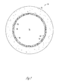
- FIG. 3 is a sectional view of the pipe of FIG. 2 according to line 3 - 3 of FIG. 2 .
- FIG. 4 is a view similar to FIG. 2 showing the bladder fully inflated in the pipe.
- FIG. 5 is a sectional view according to line 5 - 5 of FIG. 4 .
- FIG. 6 is a sectional view of the repaired pipe after the bladder has been removed.
- FIG. 7 is a sectional view according to line 7 - 7 of FIG. 6 .
- FIG. 1 is a sectional view of an exemplary structure of a pipe 10 .
- the pipe 10 has a plurality of inner diameters, including a first portion 12 having a first diameter D 1 , a second portion 16 adjacent the first portion 12 having a second diameter D 2 , and a third portion 18 having a third diameter D 3 .
- D 1 first diameter
- D 2 second diameter
- D 3 third diameter
- a variety of diameters and shapes of pipe may be present in a pipe to be rehabilitated.
- the choice of three pipe portions having various diameters is shown for illustrative purposes in this embodiment.
- the methods of this invention may be applied to an entire length of pipe in a pipeline or to portions of a pipeline having a length of pipe to be repaired.
- FIG. 2 is a sectional view of the liner assembly 30 of the present invention positioned in a pipe 10 .
- the liner assembly 30 includes a bladder 32 and a pipe liner 42 .
- the liner assembly 30 is associated with an inflation member 68 for expanding the walls of the pipe liner 42 against the wall of the pipe 10 .
- the bladder 32 comprises a first end 34 attached to the inflation member 68 near a first end 28 of the pipe 10 , a second end 36 positioned at the second end 58 of the pipe 10 , and a bladder body 38 there between.
- the first end 34 of the bladder 32 may be attached to the inflation member 68 outside of the pipe 10 as well.
- the diameter 40 of the bladder 32 is less than or equal to the smallest diameter D 1 of the pipe 10 before any stretching of the bladder 32 occurs.
- the bladder body 38 is stretchable such that it is able to press against a wall 24 of the pipe 10 when expanded.
- the pipe liner 42 is attached at the first end 28 of the pipe 10 , and comprises a pipe liner body 44 that at least partially surrounds the bladder body 38 in the pipe 10 .
- the pipe liner body 44 is comprised of lining material substantially free of coating or intermediate layers of material impervious to the resinous material 48 .
- the pipe liner 42 may also have a seamless construction.
- the resinous material 48 may be a thermoset resin, which saturates the liner and cures and hardens quicker in the presence of heat. However, it should be appreciated that other resinous materials may be used, on the condition that they are able to cure and harden.
- the pipe liner 42 is essentially a transport device, such that the resinous material 48 forms the structural properties of the liner when cured.
- the diameter 46 of the pipe liner 42 (shown in FIG. 6 ) is substantially equal to the largest diameter D 3 of the pipe 10 . Therefore, the pipe liner 42 does not need to be stretchable.
- the pipe liner 42 is positioned in the pipe 10 by pushing or pulling.
- the bladder 32 Prior to, simultaneous with, or after the pipe liner 42 is inserted into the pipe 10 , the bladder 32 is inserted into the pipe liner 42 .
- the pipe liner 42 and bladder 32 may be inserted into the pipe 10 simultaneously using an inversion method.
- An inversion method includes journaling the pipe liner 42 within the bladder 32 , and closing a first end of the liner assembly 30 using a rope, tape, tie, clamp, or the like.
- the pipe liner 42 may be impregnated with a resinous material before or after journaling within the bladder 32 .
- the liner assembly 30 is then placed within an inversion vessel (not shown), and a second opposite end of the liner assembly 30 is attached to the inversion vessel. Fluid pressure is then applied to the inversion vessel, forcing the length of liner assembly out of the inversion vessel and against the walls of the pipe.
- FIG. 3 is a top sectional view of the pipe 10 of FIG. 2 according to line 3 - 3 of FIG. 2 .
- FIG. 3 shows the bladder 32 and the pipe liner 42 positioned in the pipe 10 .
- the diameter of the bladder 32 is less than the diameter of the pipe liner 42 .
- the original diameter of the pipe liner 42 is substantially greater than the diameter D 1 of the pipe 10 at the first portion 12 . Because the diameter of the pipe liner 42 is greater than the diameter D 1 of the first portion 12 , the pipe liner will fold over itself and bunch up to fit within the first portion 12 and second portion 16 of the pipe 10 .
- FIG. 4 is a sectional view similar to FIG. 2 showing bladder 32 fully inflated in the pipe 10 .
- the bladder 32 is inflated with fluid pressure (not shown), such as air, introduced to the cavity 70 of the bladder body 38 .
- fluid pressure such as air
- the increased pressure causes the stretchable bladder body 38 to expand circumferentially towards the wall 24 of the pipe 10 .
- the expanded bladder will press the pipe liner 42 against the wall 24 of the pipe 10 . This will create a layer 62 of resinous material 48 between the pipe liner 42 and the bladder body 38 .
- the bladder body 38 will have a smooth surface abutting the layer 62 of resinous material 48 . This ensures that the resulting pipe wall 24 will be smooth and even.
- FIG. 5 shows a top sectional view of the pipe 10 of FIG. 4 according to the line 5 - 5 of FIG. 4 .
- FIG. 5 is a sectional view of the pipe 10 near the first portion 12 of the pipe 10 , where the diameter D 1 of the pipe is substantially smaller than the diameter D 3 of the third portion 18 of the pipe 10 . Because the pipe liner 42 has been sized substantially equal to the diameter D 3 of the larger section of the pipe 10 , there will be excess pipe liner body 44 at this section of pipe. The excess pipe liner body 44 will fold over itself and bunch up to create folds 52 in the liner.
- the folds 52 will compress and resinous material 48 will form a pipe liner 42 in the same way as in the larger sections of pipe, where the pipe liner 42 is a single layer.
- the compression creates a layer 62 of resinous material 48 between the pipe liner 42 and the bladder 32 .
- the thickness of the layer 62 of resinous material may vary according to the number of folds 52 or bunches in the pipe liner 42 . Since the bladder 32 was stretched to press the pipe liner 42 against the wall 24 of the pipe 10 , the bladder 32 will have a smooth surface 56 pressed against the varying layers of resinous material 48 . This will result in the resinous material having a smooth interior surface. Because the folds 52 may contain two or more layers of pipe liner 42 , the resinous material 48 will cure and harden to produce a thicker pipe wall 24 at the smaller sections of the pipe.
- FIG. 6 is a sectional view of the pipe 10 after the resinous material 48 has cured and hardened and the bladder 32 has been removed from the pipe 10 .
- the bladder 32 may be removed by deflating the fluid from the cavity 70 , and then by pulling a rope (not shown) connected to the second end 36 of the bladder 32 . Pulling the bladder 32 out first causes the bladder 32 to peel away from the cured resinous material 48 . Although peeling the bladder 32 requires the least amount of effort, it should be appreciated that the bladder 32 may also be pulled straight out of the pipe 10 from the first end 34 of the bladder 32 as well. What remains is a pipe 10 having a renewed wall 24 .
- the bladder 32 may be left in the pipe, acting as a coating for the new lining of the pipe.
- the material chosen for the bladder 32 should be compatible for adhesion with the pipe liner 42 and/or the resinous material 48 . If the materials are compatible for adhesion, the bladder will be very difficult if not impossible to peel from the cured resinous material. After the resinous material cures, the unused portions of bladder hanging within the pipe may be cut away by hand or using a remote cutting vehicle.
- the pipe liner 42 has compressed the impregnated resinous material 48 from the pipe liner body 44 , creating a cured resinous material layer 62 around the interior periphery of the pipe 10 .
- the layer 62 will be thicker in the first portion 12 of the pipe 10 because the pipe liner 42 will have folded over itself or bunched in areas.
- the folds 52 will occur in areas of the pipe 10 having a diameter less than the largest diameter D 3 of the pipe 10 .
- FIG. 7 is a top sectional view of the pipe 10 of FIG. 6 according to the line 7 - 7 of FIG. 6 .
- FIG. 7 shows that although the pipe liner 42 folded over itself, the pipe liner 42 was compressed against the smooth outer surface 56 of the bladder 32 , such that the interior periphery of the resinous material 48 cured into a smooth finish 50 .
- the folds 52 of the pipe liner 42 will cause the cured resinous layer 62 to be thicker than at the larger portions of the pipe 10 .
- the layer 62 of resinous material 48 will be substantially equal along the length of the pipe 10 , especially in embodiments where an inversion installation technique is used in the direction of larger pipe.
- the resinous material 48 will migrate from the bunched areas of liner by pressure toward the larger areas of the liner, to create a resinous surface that is smooth about the interior walls of the pipe 10 .
- the smooth finish 50 of the cured resinous material 48 allows the pipe to be used as it had previously before it required repair.
Landscapes
- Engineering & Computer Science (AREA)
- General Engineering & Computer Science (AREA)
- Mechanical Engineering (AREA)
- Manufacturing & Machinery (AREA)
- Lining Or Joining Of Plastics Or The Like (AREA)
Abstract
Description
Claims (16)
Priority Applications (2)
| Application Number | Priority Date | Filing Date | Title |
|---|---|---|---|
| US13/348,481 US9494271B2 (en) | 2012-01-11 | 2012-01-11 | Pipe liner and method of using the same |
| US15/334,436 US10295104B2 (en) | 2012-01-11 | 2016-10-26 | Pipe liner and method of using the same |
Applications Claiming Priority (1)
| Application Number | Priority Date | Filing Date | Title |
|---|---|---|---|
| US13/348,481 US9494271B2 (en) | 2012-01-11 | 2012-01-11 | Pipe liner and method of using the same |
Related Child Applications (1)
| Application Number | Title | Priority Date | Filing Date |
|---|---|---|---|
| US15/334,436 Continuation US10295104B2 (en) | 2012-01-11 | 2016-10-26 | Pipe liner and method of using the same |
Publications (2)
| Publication Number | Publication Date |
|---|---|
| US20130174979A1 US20130174979A1 (en) | 2013-07-11 |
| US9494271B2 true US9494271B2 (en) | 2016-11-15 |
Family
ID=48743091
Family Applications (2)
| Application Number | Title | Priority Date | Filing Date |
|---|---|---|---|
| US13/348,481 Expired - Fee Related US9494271B2 (en) | 2012-01-11 | 2012-01-11 | Pipe liner and method of using the same |
| US15/334,436 Expired - Fee Related US10295104B2 (en) | 2012-01-11 | 2016-10-26 | Pipe liner and method of using the same |
Family Applications After (1)
| Application Number | Title | Priority Date | Filing Date |
|---|---|---|---|
| US15/334,436 Expired - Fee Related US10295104B2 (en) | 2012-01-11 | 2016-10-26 | Pipe liner and method of using the same |
Country Status (1)
| Country | Link |
|---|---|
| US (2) | US9494271B2 (en) |
Families Citing this family (3)
| Publication number | Priority date | Publication date | Assignee | Title |
|---|---|---|---|---|
| US9945505B2 (en) * | 2015-05-15 | 2018-04-17 | Lmk Technologies, Llc | Method and apparatus for repairing a pipe using a transition tube |
| US11892114B2 (en) | 2017-03-15 | 2024-02-06 | Titan CMP Solutions LLC | Expander with accessories to adjust nominal size |
| US10746341B2 (en) | 2017-03-15 | 2020-08-18 | Titan CMP Solutions LLC | Pusher box for nondestructive pipe refurbishment in confined spaces |
Citations (25)
| Publication number | Priority date | Publication date | Assignee | Title |
|---|---|---|---|---|
| US3616061A (en) * | 1970-02-05 | 1971-10-26 | Ciba Geigy Corp | Apparatus for making curved wound articles |
| US4777984A (en) | 1986-02-10 | 1988-10-18 | British Gas Plc | Method for lining a pipe or main |
| US4976290A (en) * | 1989-06-12 | 1990-12-11 | Ozite Corporation | Tubular member having a liner |
| US5106440A (en) * | 1989-01-30 | 1992-04-21 | Tangeman Andrew F | Method for repairing manholes or wetwalls |
| US5186987A (en) | 1990-04-10 | 1993-02-16 | Ashimori Industry Co., Ltd. | Lining material for pipe lines and a process for providing pipe lines therewith |
| US5265981A (en) | 1992-06-05 | 1993-11-30 | Mcneil Ronald A | System and method for rehabilitating a manhole, and manhole rehabilitated thereby |
| US5423630A (en) | 1992-04-07 | 1995-06-13 | Ashimori Industry Co., Ltd. | Method and apparatus for repairing a pipeline |
| US5451351A (en) * | 1991-09-13 | 1995-09-19 | Composite Components, Inc. | Method for rehabilitating a pipe with a liner having an electrically conductive layer |
| US5498389A (en) | 1993-03-23 | 1996-03-12 | Shonan Gosei-Jushi Seisakusho K.K. | Method and apparatus for lining a branch pipe |
| US5501248A (en) * | 1994-06-23 | 1996-03-26 | Lmk Enterprises, Inc. | Expandable pipe liner and method of installing same |
| US5606997A (en) * | 1995-04-28 | 1997-03-04 | Advance Trenchless Rehabilitation Systems | Method for rehabilitating pipe line and resin impregnated lining having an integral heating element |
| US5762450A (en) | 1992-04-21 | 1998-06-09 | Ht Troplast Ag | System and method for relining sewer pipe sections with inspection capability |
| US5868169A (en) * | 1993-05-03 | 1999-02-09 | Catallo; Giulio | Reinforced lining hose for softlining pipe rehabilitation |
| JPH11170368A (en) | 1996-02-16 | 1999-06-29 | Shonan Gosei Jushi Seisakusho:Kk | Manhole hole lining method |
| US5950682A (en) * | 1994-08-19 | 1999-09-14 | Lmk Enterprises, Inc. | Apparatus and method for repairing the junction of a sewer main line and lateral |
| US5971029A (en) * | 1995-07-11 | 1999-10-26 | Instituform (Netherlands) B.V. | Dual containment pipe system and method of installation |
| US6206993B1 (en) | 1994-08-19 | 2001-03-27 | Lmk Enterprises, Inc. | Method and apparatus for providing a tubular material within a pipeline |
| US6401759B1 (en) | 1998-12-22 | 2002-06-11 | Shonan Gosei-Jushi Seisakusho K.K. | Liner bag for manhole and method of lining a manhole |
| US6478054B1 (en) | 2001-06-25 | 2002-11-12 | Blue Sky Forever, Inc. | Method for resin activation in pipeline repair |
| US6691741B2 (en) * | 2001-10-05 | 2004-02-17 | Nuflow Technologies (2000) Inc. | Installation assemblies for pipeline liners, pipeline liners and methods for installing the same |
| US6732763B2 (en) | 2002-05-24 | 2004-05-11 | Lantor, Inc. | Stretch-resistant pipe liner |
| WO2006128256A1 (en) | 2005-06-03 | 2006-12-07 | Shieldliner Limited | Apparatus and method for lining conduits |
| US20070113519A1 (en) | 2005-11-23 | 2007-05-24 | Lmk Enterprises, Inc. | Method of repairing a manhole chimney using a stretchable sleeve |
| US20090194183A1 (en) * | 2008-02-05 | 2009-08-06 | Lmk Enterprises, Inc. | Bladder and method for cured-in-place pipe lining |
| US8821068B2 (en) | 2010-07-12 | 2014-09-02 | Lmk Technologies, Llc | Manhole liner and method of using the same |
-
2012
- 2012-01-11 US US13/348,481 patent/US9494271B2/en not_active Expired - Fee Related
-
2016
- 2016-10-26 US US15/334,436 patent/US10295104B2/en not_active Expired - Fee Related
Patent Citations (28)
| Publication number | Priority date | Publication date | Assignee | Title |
|---|---|---|---|---|
| US3616061A (en) * | 1970-02-05 | 1971-10-26 | Ciba Geigy Corp | Apparatus for making curved wound articles |
| US4777984A (en) | 1986-02-10 | 1988-10-18 | British Gas Plc | Method for lining a pipe or main |
| US5106440A (en) * | 1989-01-30 | 1992-04-21 | Tangeman Andrew F | Method for repairing manholes or wetwalls |
| US4976290A (en) * | 1989-06-12 | 1990-12-11 | Ozite Corporation | Tubular member having a liner |
| US5186987A (en) | 1990-04-10 | 1993-02-16 | Ashimori Industry Co., Ltd. | Lining material for pipe lines and a process for providing pipe lines therewith |
| US5451351A (en) * | 1991-09-13 | 1995-09-19 | Composite Components, Inc. | Method for rehabilitating a pipe with a liner having an electrically conductive layer |
| US5423630A (en) | 1992-04-07 | 1995-06-13 | Ashimori Industry Co., Ltd. | Method and apparatus for repairing a pipeline |
| US5762450A (en) | 1992-04-21 | 1998-06-09 | Ht Troplast Ag | System and method for relining sewer pipe sections with inspection capability |
| US5265981A (en) | 1992-06-05 | 1993-11-30 | Mcneil Ronald A | System and method for rehabilitating a manhole, and manhole rehabilitated thereby |
| US5498389A (en) | 1993-03-23 | 1996-03-12 | Shonan Gosei-Jushi Seisakusho K.K. | Method and apparatus for lining a branch pipe |
| US5868169A (en) * | 1993-05-03 | 1999-02-09 | Catallo; Giulio | Reinforced lining hose for softlining pipe rehabilitation |
| US5501248A (en) * | 1994-06-23 | 1996-03-26 | Lmk Enterprises, Inc. | Expandable pipe liner and method of installing same |
| US5950682A (en) * | 1994-08-19 | 1999-09-14 | Lmk Enterprises, Inc. | Apparatus and method for repairing the junction of a sewer main line and lateral |
| US6206993B1 (en) | 1994-08-19 | 2001-03-27 | Lmk Enterprises, Inc. | Method and apparatus for providing a tubular material within a pipeline |
| US5606997A (en) * | 1995-04-28 | 1997-03-04 | Advance Trenchless Rehabilitation Systems | Method for rehabilitating pipe line and resin impregnated lining having an integral heating element |
| US5971029A (en) * | 1995-07-11 | 1999-10-26 | Instituform (Netherlands) B.V. | Dual containment pipe system and method of installation |
| JPH11170368A (en) | 1996-02-16 | 1999-06-29 | Shonan Gosei Jushi Seisakusho:Kk | Manhole hole lining method |
| US6401759B1 (en) | 1998-12-22 | 2002-06-11 | Shonan Gosei-Jushi Seisakusho K.K. | Liner bag for manhole and method of lining a manhole |
| US6478054B1 (en) | 2001-06-25 | 2002-11-12 | Blue Sky Forever, Inc. | Method for resin activation in pipeline repair |
| US6691741B2 (en) * | 2001-10-05 | 2004-02-17 | Nuflow Technologies (2000) Inc. | Installation assemblies for pipeline liners, pipeline liners and methods for installing the same |
| US6732763B2 (en) | 2002-05-24 | 2004-05-11 | Lantor, Inc. | Stretch-resistant pipe liner |
| WO2006128256A1 (en) | 2005-06-03 | 2006-12-07 | Shieldliner Limited | Apparatus and method for lining conduits |
| US20080277838A1 (en) | 2005-06-03 | 2008-11-13 | Brian Maxwell Hassen | Apparatus and Method For Lining Conduits |
| US20070113519A1 (en) | 2005-11-23 | 2007-05-24 | Lmk Enterprises, Inc. | Method of repairing a manhole chimney using a stretchable sleeve |
| US7670086B2 (en) | 2005-11-23 | 2010-03-02 | Lmk Enterprises, Inc. | Method of repairing a manhole chimney using a stretchable sleeve |
| US20090194183A1 (en) * | 2008-02-05 | 2009-08-06 | Lmk Enterprises, Inc. | Bladder and method for cured-in-place pipe lining |
| US8821068B2 (en) | 2010-07-12 | 2014-09-02 | Lmk Technologies, Llc | Manhole liner and method of using the same |
| US20140341655A1 (en) | 2010-07-12 | 2014-11-20 | Lmk Technologies, Llc | Manhole liner and method of using the same |
Non-Patent Citations (2)
| Title |
|---|
| JP 11 170368, Yokoshima & Co.-English Abstract, 1 page, Jun. 29, 1999. |
| LMK Enterprises, Inc. PCT/US11/43345, International Search Report dated Jan. 1, 2012, 2 pages. |
Also Published As
| Publication number | Publication date |
|---|---|
| US20130174979A1 (en) | 2013-07-11 |
| US10295104B2 (en) | 2019-05-21 |
| US20170045176A1 (en) | 2017-02-16 |
Similar Documents
| Publication | Publication Date | Title |
|---|---|---|
| US5609439A (en) | Method of and apparatus for repairing and sealing junctions between mains and branch pipes | |
| US8550121B2 (en) | Method and apparatus for lining a pipe | |
| US9851040B2 (en) | Apparatus and method to repair the junction of a sewer main line and lateral pipe | |
| US8118063B2 (en) | Method and apparatus for lining a pipe | |
| US9074338B2 (en) | Manhole liner and method of using the same | |
| US9435479B2 (en) | Device and method for repairing pipe | |
| US20160178108A1 (en) | Repair and reinforcement of pressurized pipes | |
| AU651092B2 (en) | Pipeline and passageway lining materials | |
| JPH04327090A (en) | Method of repairing part of underground conduit | |
| US6682668B1 (en) | Installation of cured in place liners with an endless reusable inflation bladder and installation apparatus | |
| US20130098535A1 (en) | Method and apparatus for forming a coating on a lining of a conduit in situ | |
| US9074720B2 (en) | Apparatus and method for repairing pipes | |
| US10295104B2 (en) | Pipe liner and method of using the same | |
| RU2145029C1 (en) | Method for pipeline facing | |
| US10386006B2 (en) | Method and apparatus for rehabilitation of water conduit with lateral openings | |
| FI125955B (en) | Remediation hose and method for mounting an remediation hose in a pipe system | |
| JP2011025456A (en) | Pipe lining method and lining pipe | |
| JP4719086B2 (en) | Repair method for pipelines with branch pipes | |
| JPH08216256A (en) | Pipe lining method | |
| EP0819231B1 (en) | Branched sewer re-lining | |
| CN115507245B (en) | Lining tube for repairing pipeline and preparation method | |
| JP3216330B2 (en) | Pipeline lining method, lining material and lined pipe | |
| JP2000094521A (en) | Method for lining inside of pipe | |
| AU652245B2 (en) | Method for the repair of localised damaged portions of a cement sewer pipe laid beneath the surface of the ground | |
| GB2425815A (en) | Lining fluid conduits |
Legal Events
| Date | Code | Title | Description |
|---|---|---|---|
| AS | Assignment |
Owner name: LMK ENTERPRISES, INC., ILLINOIS Free format text: ASSIGNMENT OF ASSIGNORS INTEREST;ASSIGNOR:KIEST, LARRY W., JR;REEL/FRAME:027685/0911 Effective date: 20120208 |
|
| AS | Assignment |
Owner name: LMK TECHNOLOGIES, LLC, ILLINOIS Free format text: ASSIGNMENT OF ASSIGNORS INTEREST;ASSIGNOR:LMK ENTERPRISES, INC.;REEL/FRAME:028571/0118 Effective date: 20120713 |
|
| STCF | Information on status: patent grant |
Free format text: PATENTED CASE |
|
| AS | Assignment |
Owner name: ARES CAPITAL CORPORATION., AS COLLATERAL AGENT, NE Free format text: GRANT OF SECURITY INTEREST IN PATENT RIGHTS;ASSIGNORS:PERMA-LINER INDUSTRIES, LLC;ACTION PRODUCTS MARKETING CORP.;LMK TECHNOLOGIES, LLC;REEL/FRAME:048991/0468 Effective date: 20190409 Owner name: ARES CAPITAL CORPORATION., AS COLLATERAL AGENT, NEW YORK Free format text: GRANT OF SECURITY INTEREST IN PATENT RIGHTS;ASSIGNORS:PERMA-LINER INDUSTRIES, LLC;ACTION PRODUCTS MARKETING CORP.;LMK TECHNOLOGIES, LLC;REEL/FRAME:048991/0468 Effective date: 20190409 |
|
| MAFP | Maintenance fee payment |
Free format text: PAYMENT OF MAINTENANCE FEE, 4TH YR, SMALL ENTITY (ORIGINAL EVENT CODE: M2551); ENTITY STATUS OF PATENT OWNER: SMALL ENTITY Year of fee payment: 4 |
|
| AS | Assignment |
Owner name: ADAMS STREET CREDIT ADVISORS LP, ILLINOIS Free format text: SECURITY INTEREST;ASSIGNORS:ACTION PRODUCTS MARKETING, LLC;LMK TECHNOLOGIES LLC;MORAY GROUP, LLC;AND OTHERS;REEL/FRAME:058598/0447 Effective date: 20211029 |
|
| AS | Assignment |
Owner name: LMK TECHNOLOGIES, LLC, ILLINOIS Free format text: RELEASE BY SECURED PARTY;ASSIGNOR:ARES CAPITAL CORPORATION, AS COLLATERAL AGENT;REEL/FRAME:058001/0984 Effective date: 20211029 Owner name: ACTION PRODUCTS MARKETING CORP., IOWA Free format text: RELEASE BY SECURED PARTY;ASSIGNOR:ARES CAPITAL CORPORATION, AS COLLATERAL AGENT;REEL/FRAME:058001/0984 Effective date: 20211029 Owner name: PERMA-LINER INDUSTRIES, LLC, FLORIDA Free format text: RELEASE BY SECURED PARTY;ASSIGNOR:ARES CAPITAL CORPORATION, AS COLLATERAL AGENT;REEL/FRAME:058001/0984 Effective date: 20211029 |
|
| LAPS | Lapse for failure to pay maintenance fees |
Free format text: PATENT EXPIRED FOR FAILURE TO PAY MAINTENANCE FEES (ORIGINAL EVENT CODE: EXP.); ENTITY STATUS OF PATENT OWNER: SMALL ENTITY |
|
| STCH | Information on status: patent discontinuation |
Free format text: PATENT EXPIRED DUE TO NONPAYMENT OF MAINTENANCE FEES UNDER 37 CFR 1.362 |
|
| FP | Lapsed due to failure to pay maintenance fee |
Effective date: 20241115 |