US9490519B2 - Transmission line transformer antenna - Google Patents
Transmission line transformer antenna Download PDFInfo
- Publication number
- US9490519B2 US9490519B2 US14/662,982 US201514662982A US9490519B2 US 9490519 B2 US9490519 B2 US 9490519B2 US 201514662982 A US201514662982 A US 201514662982A US 9490519 B2 US9490519 B2 US 9490519B2
- Authority
- US
- United States
- Prior art keywords
- transmission lines
- increasing material
- transmission line
- amount
- impedance increasing
- Prior art date
- Legal status (The legal status is an assumption and is not a legal conclusion. Google has not performed a legal analysis and makes no representation as to the accuracy of the status listed.)
- Active - Reinstated, expires
Links
Images


Classifications
-
- H—ELECTRICITY
- H01—ELECTRIC ELEMENTS
- H01P—WAVEGUIDES; RESONATORS, LINES, OR OTHER DEVICES OF THE WAVEGUIDE TYPE
- H01P5/00—Coupling devices of the waveguide type
- H01P5/02—Coupling devices of the waveguide type with invariable factor of coupling
-
- H—ELECTRICITY
- H01—ELECTRIC ELEMENTS
- H01P—WAVEGUIDES; RESONATORS, LINES, OR OTHER DEVICES OF THE WAVEGUIDE TYPE
- H01P3/00—Waveguides; Transmission lines of the waveguide type
- H01P3/02—Waveguides; Transmission lines of the waveguide type with two longitudinal conductors
- H01P3/06—Coaxial lines
-
- H—ELECTRICITY
- H01—ELECTRIC ELEMENTS
- H01P—WAVEGUIDES; RESONATORS, LINES, OR OTHER DEVICES OF THE WAVEGUIDE TYPE
- H01P5/00—Coupling devices of the waveguide type
- H01P5/12—Coupling devices having more than two ports
-
- H—ELECTRICITY
- H01—ELECTRIC ELEMENTS
- H01Q—ANTENNAS, i.e. RADIO AERIALS
- H01Q1/00—Details of, or arrangements associated with, antennas
- H01Q1/50—Structural association of antennas with earthing switches, lead-in devices or lightning protectors
Definitions
- the present invention generally relates to hand held communication devices employing whip antennas.
- a whip antenna is an antenna having a single straight flexible wire or rod. The bottom end of the whip is connected to the radio receiver or transmitter.
- the band is typically in the range of 2-30 MHz.
- the shorter frequencies have the ability to follow the contours of Earth. This is one of the few benefits over high frequency communications, which may be more limited to line of sight.
- the whip length should increase to maintain efficiency.
- Some conventional hand-held whip antenna communication devices that operate in the 90-500 MHz band have a whip antenna of lengths of about four feet. Such a length is not very practical for a hand-held device.
- a tri-fold version provides a collapsible antenna having a much shorter length when not in use. However the folded antenna must be deployed to the full 4 ft length for use.
- Another type of conventional hand-held whip antenna communication device uses a twelve inch whip antenna. This conventional “short” whip antenna employs a transformer to reduce impedance mismatch between the signal generator and the antenna. This will be described in reference to FIG. 1 .
- FIG. 1 illustrates a short whip antenna transmission system 100 .
- transmission system 100 includes a signal generator 102 , a transformer 104 and an antenna 106 .
- Signal generator 102 is connected to transformer 104 at a node 108 and transformer 104 is connected to antenna 106 at a node 110 .
- Signal generator 102 generates an alternating current signal for use by antenna 106 to transmit a corresponding radiated signal.
- Transformer 104 reduces an impedance mismatch between signal generator 102 and antenna 106 .
- Antenna 106 is a short whip antenna for transmitting in the 90-500 MHz range.
- the output impedance of signal generator 102 , at node 110 is 50 ⁇ and the input impedance of antenna, at node 110 , is 300 ⁇ .
- Such an impedance mismatch would drastically reduce the efficiency of transmission system 100 .
- Tremendous heat is generated by transformer 104 .
- a heat sink is used to transfer and dissipate heat to the environment. This will be described with reference to FIG. 2 .
- FIG. 2 illustrates a conventional short antenna 200 for transmitting at least 90 MHz.
- conventional short antenna 200 includes a connector 202 , a circuit board 204 , a short whip antenna portion 206 and a heat sink 208 .
- Circuit board 204 includes a toroidal transformer 210 .
- Connector 202 is connected to circuit board 204 , which is additionally connected to short whip antenna portion 206 .
- Heat sink 208 is thermally connected to toroidal transformer 210 .
- Connector 202 receives a signal from a signal generator (not shown) and conducts the signal to circuit board 204 .
- a signal generator not shown
- short whip antenna portion 206 has an input impedance of 300 ⁇ .
- toroidal transformer 210 provides an impedance matching function.
- toroidal transformer 210 generates heat, which is dissipated via heat sink 208 .
- FIG. 3 illustrates a cross-sectional view of heat sink 208 along plane X-X of FIG. 2 .
- heat sink 208 includes a tubular body 302 and a plurality of heat fins, a sample of which is numbered 304 .
- Tubular body has a hollow center 306 .
- tubular body 302 of heat sink 208 As heat is generated by toroidal transformer 210 , the heat is conducted to tubular body 302 of heat sink 208 . Tubular body 302 then conducts the heat through its fins, for dissipation to the environment.
- Connector 202 may be a standard coaxial connector.
- Heat sink 208 is manufactured to fit connector 202 and connect to standard short whip antennas, such as short whip antenna portion 206 .
- the combined function of the impedance matching of toroidal transformer 210 with the heat dissipating function of heat sink 208 enables to somewhat efficient short whip antenna hand held communication device operable at lower frequencies. This will be described with reference to FIG. 4 .
- FIG. 4 illustrates a graph 400 of VSWR as a function of frequency of the driving signal.
- graph 400 includes a Y-axis 402 , an X-axis 404 , a function 406 , a function 408 , a function 410 , and a dotted line 412 .
- Y-axis 402 is a voltage standing wave ratio (VSWR).
- a standing wave ratio (SWR) is a measure of impedance matching of loads to the characteristic impedance of a transmission line. The SWR may be thought of in terms of the maximum and minimum AC voltages along the transmission line, thus being called the VSWR.
- Y-axis 402 is the VSWR and is measured logarithmically. It is a goal to reduce the VSWR as much as possible for the band with which a transmitter will be transmitting. In other words, with the respect to VSWR, the lower—the better.
- X-axis 404 is frequency in MHz of the transmitted signal.
- Function 406 corresponds to the VSWR as a function of frequency of to transmission system having a four foot long whip antenna.
- Function 408 corresponds to the VSWR as a function of frequency of a transmission system having a four foot long tri-fold whip antenna.
- Function 410 corresponds to the VSWR as a function of frequency of a transmission system having a short whip antenna as illustrated in FIG. 2 .
- Dotted line 412 represents a VSWR threshold for a particular transmitter requirement.
- dotted line 412 highlights a VSWR value of 3.
- function 406 has a VSWR value below 3 from about 80-120 MHz
- function 408 has a VSWR value below 3 from about 80-105 MHz
- Function 410 has a VSWR value below 3 at greater than about 90 MHz.
- What is needed is a short whip antenna that can provide a VSWR value below 3 at less than 90 MHz and that can fit within a conventional heat sink as shown in FIG. 2 .
- the present invention provides a short whip antenna that can provide a VSWR value below 3 at less than 90 MHz and that can fit within a conventional heat sink as shown in FIG. 2
- An aspect of the present invention is drawn to device that includes an input port, an antenna, an output port, a transmission line transformer, a first amount of a first impedance increasing material and a second amount of a second impedance increasing material.
- the input port can receive an unbalanced input radio frequency signal.
- the antenna can transmit an unbalanced transmission signal based on the input radio frequency signal.
- the output port is connected to the antenna.
- the transmission line transformer is disposed between the input port and the output port.
- the transmission line transformer includes n transmission lines, wherein each of the n transmission lines has a first end, a second end separated from the first end by a length, an axial conducting core and a coaxial conducting sheathing electrically separated from the axial conducting core.
- Each of the coaxial conducting sheathings is connected to ground at the first end.
- An axial conducting core at a second end of one of the transmission lines is electrically connected to a second end of a coaxial conducting sheathing of another of the transmission lines.
- An axial conducting core at the second end of the another of the transmission lines is electrically connected to the output port.
- the first amount of a first impedance increasing material is disposed with the one of the transmission lines to inhibit common-mode current from flowing on the outer surface of the coaxial conducting sheathing of the one of the transmission lines.
- the second amount of a second impedance increasing material is disposed with another of the transmission lines to inhibit common-mode current from flowing on the outer surface of the coaxial conducting sheathing of the another of the transmission lines.
- the second amount of a second impedance increasing material is greater than the first amount of a first impedance increasing material.
- FIG. 1 illustrates a short whip antenna transmission system
- FIG. 2 illustrates a conventional short antenna for transmitting at least 90 MHz
- FIG. 3 illustrates a cross-sectional view of the heat sink along plane X-X of FIG. 2 ;
- FIG. 4 illustrates a graph of the efficiently radio-frequency power as transmitted from a power source, through a transmission line, into a load as a function of frequency of the driving signal;
- FIG. 5 illustrates a short whip antenna transmission system for transmitting at least 30 MHz
- FIG. 6 illustrates a schematic of the transformer of FIG. 5 ;
- FIG. 7 illustrates common-mode currents within transmission system of FIG. 5 ;
- FIG. 8 illustrates another short whip transmission system for transmitting at least 30 MHz.
- FIG. 9 illustrates a cross-sectional view of heat sink of FIG. 2 along plane X-X, if it were attempted to be used in conjunction with the transformer of FIG. 8 ;
- FIG. 10 illustrates an example short whip transmission system for transmitting below 30 MHz in accordance with aspects of the present invention
- FIG. 11 illustrates a cross-sectional view of the heat sink of FIG. 2 along plane X-X, as used in conjunction with the transformer of FIG. 10 ;
- FIG. 12 illustrates another graph of the efficiently radio-frequency power as transmitted from a power source, through a transmission line, into a load as a function of frequency of the driving signal;
- FIG. 13 illustrates another example short whip transmission system in accordance with aspects of the present invention.
- FIG. 14 illustrates another example short whip transmission system in accordance with aspects of the present invention.
- the present invention is drawn a short whip antenna using a transmission line transformer for impedance matching, between the signal generator and the short whip antenna.
- the transmission line transformer uses specifically displaced beads of impedance increasing material on the coaxial transmission line transformers.
- the beads of impedance increasing material greatly reduce induced back currents (common-mode currents) on the outer surfaces of the coaxial transmission line transformers, which decreases interference with the transmitted signal from the short Whip antenna.
- the specific displacement of the beads enables the coaxial transmission line transformers to be compactly disposed within a heat sink.
- Transmission line transformers are well known. However, they are typically used between a balanced input and unbalanced output—as a “balun.” In accordance with aspects of the present invention, a transmission line transformer is used between an unbalance input and an unbalanced output—as an “unun.”
- a coaxial transmission line transformer In a balanced system, a coaxial transmission line transformer carries equal and opposite currents on its outer conducting sheathing and its inner conducting core. In an unbalanced system, the currents on the outer conducting sheathing and the inner conducting core are unequal. Unopposed current on the outer conducting sheathing is called common-mode current, which promotes external coupling and radiation, increases network losses, and raises VSWR. These effects are detrimental to the efficiency and performance of an antenna, and therefore should be minimized.
- connector 202 is a coaxial connector and is therefore an unbalanced input.
- short whip antenna portion 206 is an unbalanced input.
- a transmission line transformer in accordance with aspects of the present invention may be used in conjunction with connector 202 and short whip antenna portion 206 . In this manner, a transmission line transformer in accordance with aspects of the present invention is an unbalanced to unbalanced transformer, or an unun transformer.
- a first aspect of the invention is drawn to the use of a transmission line transformer for impedance matching between an unbalance input line and an unbalanced short whip antenna. This aspect will be described with reference to FIGS. 5-6 .
- FIG. 5 illustrates a short whip antenna transmission system 500 for transmitting at least 30 MHz.
- transmission system 500 includes signal generator 102 , impedance-matching resistor 502 , a transmission line transformer 504 and antenna 106 .
- Signal generator 102 is connected to impedance-matching resistor 502 at a node 506 .
- Impedance-matching resistor 502 is connected to transmission, line transformer 504 at as node 508 and transmission line transformer 504 is connected to antenna 106 at node 110 .
- Transmission line transformer 504 includes a coaxial transmission line 510 , a coaxial transmission line 512 , a coaxial transmission line 514 , a conducting line 516 , a conducting line 518 , a conducting line 520 , a conducting line 522 and a conducting line 524 .
- Coaxial transmission line 510 has an end 526 , an end 528 , an inner conducting core 530 and an outer conducting sheathing 532 .
- Coaxial transmission line 512 has an end 534 , an end 536 , an inner conducting core 538 and an outer conducting sheathing 540 .
- Coaxial transmission line 514 has an end 542 , an end 544 , an inner conducting core 546 and an outer conducting sheathing 548 .
- Inner conducting core 530 at end 526 , inner conducting core 538 at end 534 and inner conducting core 546 at end 542 are connected at node 508 .
- Outer conducting sheathing 532 at end 526 is connected to outer conducting sheathing 540 at end 534 via conducting line 516 .
- Outer conducting sheathing 540 at end 534 is connected to outer conducting sheathing 548 at end 542 via conducting line 518 .
- Inner conducting core 546 at end 544 is connected to outer conducting sheathing 540 at end 536 via conducting line 524 .
- Inner conducting core 538 at end 536 is connected to outer conducting sheathing 532 at end 528 via conducting line 522 .
- Inner conducting core 530 is connected to node 110 via conducting line 520 .
- coaxial transmission lines 510 , 512 and 514 are arranged in parallel with node 508 , but are arranged in series with respect to node 110 .
- each of coaxial transmission lines 510 , 512 and 514 have equal impedance.
- a signal 550 generated by signal generator 102 is split evenly between coaxial transmission lines 510 , 512 and 514 , wherein inner conducting core 530 receives a signal 552 , inner conducting core 538 receives a signal 554 and inner conducting core 556 receives a signal 556 .
- a signal 558 conducts from inner conducting core 546 at end 544 through line 524 to ground via outer conducting sheathing 540 .
- a signal 560 conducts from inner conducting core 538 at end 536 through line 522 to ground via outer conducting sheathing 532 .
- a signal 562 conducts from inner conducting core 530 at end 528 through line 520 to antenna 106 via node 110 .
- FIG. 6 illustrates a schematic of transmission line transformer 504 of FIG. 5 .
- dotted rectangle 602 corresponds to coaxial transmission line 510
- dotted rectangle 604 corresponds to coaxial transmission line 512
- dotted rectangle 606 corresponds to coaxial transmission line 514 .
- the inside of each of dotted rectangle 602 , 604 and 606 are illustrated as a winding, inductor-type of transformer merely to illustrate that each acts as a transformer in the RF region.
- the upper winding corresponds to the inner conducting core of the corresponding coaxial transmission line
- the lower winding corresponds to the outer conducting sheathing of the corresponding coaxial transmission line.
- outer conducting sheathing 532 of coaxial transmission line 510 As shown by a node 608 line 516 , line 518 and a portion of dotted rectangle 606 are connected to ground. As such as additionally shown in FIG. 5 , outer conducting sheathing 532 of coaxial transmission line 510 , outer conducting sheathing 540 of coaxial transmission line 512 and outer conducting sheathing 548 of coaxial transmission line 514 are all connected to ground.
- a voltage V 1 is generated between outer conducting sheathing 548 (at ground) and inner conducting core 546 of coaxial transmission line 514 as provided by node 508 .
- V 1 is conducted to outer conducting sheathing 540 (also at ground).
- a voltage V 2 is generated between outer conducting sheathing 540 (at ground) and inner conducting core 538 of coaxial transmission line 512 as provided by node 508 .
- V 2 is conducted to outer conducting sheathing 532 (also at ground).
- a voltage V 3 is generated between outer conducting sheathing 532 (at ground) and inner conducting core 530 of coaxial transmission line 510 as provided by node 508 .
- V 3 is conducted to node 110 via line 520 .
- a signal generator was used that included an output impedance (at node 506 ) of about 50 ⁇ and a short whip antenna included an input impedance of about 300 ⁇ (at node 110 ).
- a coaxial cable having an impedance of 93 ⁇ was chosen for the transmission line transformer, as it was readily commercially available.
- Z 538 is the impedance of inner conducting core 538 and Z 546 is the impedance of inner conducting core 546 .
- the input impedance as viewed from node 108 is 31 ⁇ (i.e., 93 ⁇ /3) because they are arranged in parallel.
- the output impedance from at node 110 would then be 279 ⁇ (i.e., 3 2 *31),
- the output impedance of transmission line transformer 504 of 279 ⁇ closely matches the 300 ⁇ input impedance of short whip antenna 106 .
- a 7.5 ⁇ resistor is added as impedance-matching resistor 502 .
- transmission line transformer 504 may effectively match the output impedance at node 508 with the input impedance at node 110 , as mentioned earlier, there are common-mode currents generated that must be addressed. In particular, if common-mode currents are allowed to flow, these currents will effectively short node 508 to ground. This will occur because coaxial transmission lines 510 , 512 and 514 are electrically short (in wavelengths). The effect of shorting the input (node 508 in this case) to ground will destroy all performance. This is obvious if one evaluates the network at DC. Only if common-mode currents (currents flowing on the outside surfaces of conducting sheathing 532 and conducting sheathing 540 ) are eliminated or drastically reduced, does the transmission-line transformer perform as discussed with reference to FIG. 6 .
- FIG. 7 illustrates common-mode currents within transmission system 500 .
- V 1 at end 544 of coaxial transmission line 514 unbalances the currents between conducting core 546 and conducting coaxial sheathing 548 . This unbalance creates a common-mode current 706 toward ground.
- V 2 at end 536 of coaxial transmission line 512 unbalances the currents between conducting core 538 and conducting coaxial sheathing 540 . This unbalance creates a common-mode current 704 toward ground. Because V 2 includes V 1 , common-mode current 704 is twice the magnitude of common-mode current 706 . Finally, V 3 at end 528 of coaxial transmission line 510 unbalances the currents between conducting core 530 and conducting coaxial sheathing 532 . This unbalance creates a common-mode current 702 toward ground. Because V 3 includes V 1 and V 2 , common-mode current 702 is three times the magnitude of common-mode current 706 .
- Conducting line 524 is at voltage V 1 and thus raises the potential of end 536 to V 1 . This voltage tries to induce a current to flow back to ground on the outside of coaxial transmission line 512 . If coaxial transmission lines 510 , 512 and 514 are short (in wavelengths, which these are), then no significant amount of current 558 can be allowed to flow back to node 508 as common-mode current 704 . To the extent that current 558 flows into common-mode current 704 , it would “short” the outer conducting sheathing 548 back to ground (0 volts), thus eliminating the desired stepped-up voltage effect for from transmission line transformer 504 .
- conducting line 522 is trying to raise the voltage on outer conducting sheathing 532 of coaxial transmission lines 510 at end 528 to 2V 1 .
- This double voltage tries twice as hard to induce common-mode current 702 to short out the stepped-up voltage.
- no current choke is needed on coaxial transmission line 514 because common-mode currents flowing in coaxial transmission line 514 are of relatively little concern.
- Common-mode current chokes on coaxial transmission lines 512 and 510 and the choking effects needed are proportional to the voltages trying to induce common-mode current to flow.
- twice the choking effect is needed on coaxial transmission line 510 as on coaxial transmission line 512 , because the voltage on end 528 is twice the voltage as on end 536 .
- Common-mode currents 702 , 704 and 706 each oscillate in accordance with the frequency of signal 550 as provided by signal generator 102 .
- the direct connection effect of common-mode currents 702 , 704 and 706 degrades the desired matching network performance by shorting input to ground, reducing input impedance, and reducing the desired current flowing into short whip antenna 106 . This all leads to reduced radiation from short whip antenna 106 and increased losses, as all of that extra current flows through matching resistor 502 and other lossy elements. Accordingly, it is a goal to eliminate—or at the very least drastically reduce—common-mode currents in a transmission line transformer used with a short whip antenna. This may be accomplished by choking the common-mode currents using increased impedance material on the transmission lines within the transmission line transformer. This will be described in greater detail with reference to FIG. 8 .
- FIG. 8 illustrates another short whip transmission system 800 for transmitting at least 30 MHz.
- transmission system 800 includes signal generator 102 , impedance-matching resistor 502 , a transmission line transformer 802 and antenna 106 .
- Impedance-matching resistor 502 is connected to transmission line transformer 802 at a node 508 and transmission line transformer 802 is connected to antenna 106 at a node 110 .
- Transmission line transformer 802 includes coaxial transmission line 510 , coaxial transmission line 512 , coaxial transmission line 514 , conducting line 516 , conducting line 518 , conducting line 520 , conducting line 522 , conducting line 524 , an impedance increasing material 804 , an impedance increasing material 806 and an impedance increasing material 808 .
- Impedance increasing material 804 surrounds the length of coaxial transmission line 510 .
- Impedance increasing material 806 surrounds the length of coaxial transmission line 512 .
- Impedance increasing material 808 surrounds the length of coaxial transmission line 514 .
- Impedance increasing material 804 acts as a common-mode current choke prevent common-mode currents on coaxial transmission line 510 .
- impedance increasing material 806 acts as a common-mode current choke on coaxial transmission line 512 and impedance increasing material 808 acts as a common-mode current choke on coaxial transmission line 514 .
- a problem with employing impedance increasing material on all the coaxial transmission lines within a transmission line transformer is that the cross-sectional area of the transmission line transformer is increased. If the transformer must be used within a predefined are, such as within heat sink 208 of FIG. 2 , it will not fit. This will be described in greater detail with reference to FIG. 9 .
- FIG. 9 illustrates a cross-sectional view of heat sink 208 along plane X-X of FIG. 2 , if it were attempted to be used in conjunction with transmission line transformer 802 .
- coaxial transmission line 510 with impedance increasing material 804 , coaxial transmission line 512 impedance increasing material 806 and coaxial transmission line 514 impedance increasing material 808 are situated so as to be enclosed within hollow center 306 of tubular body 302 .
- beads of impedance increasing material are disposed so as to minimize the cross-sectional area of the transmission line transformer. This will be described with additional reference to FIG. 10 .
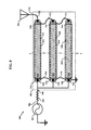
- FIG. 10 illustrates an example short whip transmission system 1000 for transmitting below 30 MHz in accordance with aspects of the present invention.
- transmission system 1000 includes signal generator 102 , impedance-matching resistor 502 , a transmission line transformer 1002 and antenna 106 .
- Impedance-matching resistor 502 is connected to transmission line transformer 1002 at a node 508 and transmission line transformer 1002 is connected to antenna 106 at a node 110 .
- Transmission line transformer 1002 includes coaxial transmission line 510 , coaxial transmission line 512 , coaxial transmission line 514 , conducting line 516 , conducting line 518 , conducting line 520 , conducting line 522 , conducting line 524 , a bead 1004 of impedance increasing material, a bead 1006 of impedance increasing material and a bead 1008 of impedance increasing material.
- Bead 1004 surrounds a portion coaxial transmission line 510
- bead 1006 surrounds another portion of coaxial transmission line 510
- bead 1008 surrounds a portion of coaxial transmission line 512 .
- Bead 1004 is longitudinally separated from bead 1006 by a distance d.
- Bead 1008 had a width w.
- beads of impedance increasing material provide a stepped common-mode current reduction to maximize common-mode current reduction while minimizing the cross sectional area of the transmission line transformer.
- Bead 1008 is a first step of a common-mode current choke, which in this ease is for coaxial transmission line 512 .
- Beads 1004 and 1006 are a second increased step of a common-mode current choke, which in this case is for coaxial transmission line 510 .
- common-mode current 702 is much larger in magnitude than common-mode current 704 , it requires the largest common-mode current choke.
- coaxial transmission line 510 has two beads of impedance increasing material.
- common-mode current 704 requires less common-mode current choke than common-mode current 702 .
- coaxial transmission line 512 only has one bead of impedance increasing material. In this case, beads 1004 and 1006 are sufficient to choke common-mode current 702 and bead 1008 is sufficient to choke common-mode current 704 .
- common-mode current 706 in coaxial transmission line 514 is so sufficiently small that its negligible, negative affect on the radiated signal from short whip antenna 106 can be tolerated at the expense of the saved cross sectional area from not having impedance increasing material.
- FIG. 11 illustrates a cross-sectional view of heat sink 208 along plane X-X of FIG. 2 , as used in conjunction with transmission line transformer 1002 .
- coaxial transmission line 510 coaxial transmission line 512 and coaxial transmission line 514 are situated so as to be enclosed within hollow center 306 of tubular body 302 .
- bead 1008 on coaxial transmission line 512 fits between beads 1004 and 1006 , so as to rest on coaxial transmission line 510 .
- beads 1004 and 1006 on coaxial transmission line 510 fit around bead 1008 , so as to rest on coaxial transmission line 512 .
- coaxial transmission line 514 can rest against beads 1004 , 1006 and 1008 .
- FIG. 12 illustrates a graph 1200 of VSWR as a function of frequency of the driving signal.
- graph 1200 includes Y-axis 402 , X-axis 404 , function 406 , function 408 , function 410 , a function 1202 and dotted line 412 .
- Function 1202 corresponds to the VSWR as a function of frequency of a transmission system having a short whip antenna similar to that as illustrated in FIG. 2 , but using transmission line transformer 1002 of FIG. 10 .
- function 1002 has a VSWR value below 3 from about 30-120 MHz and greater than about 210 MHz. Further function 1002 has a VSWR value below 4 from about 120-210 MHz.
- the example transmission line transformer discussed above with reference to FIG. 10 includes three coaxial transmission lines. However, any number greater than two may be used. As discussed above with reference to equations (1) and (2), the output voltage as a function of the input voltage and the output impedance as a function of the input impedance may be determined fur the number of coaxial transmission lines used. Other example transmission line transformers will now be described with reference to FIGS. 13-14 .
- FIG. 13 illustrates another example short whip transmission system 1300 in accordance with aspects of the present invention.
- transmission system 1300 includes signal generator 102 , impedance-matching resistor 502 , a transmission line transformer 1302 and antenna 106 .
- Impedance-matching resistor 502 is connected to transmission line transformer 1302 at a node 508 and transmission line transformer 1302 is connected to antenna 106 at a node 110 .
- Transmission line transformer 1302 includes coaxial transmission line 510 , coaxial transmission line 512 , conducting line 516 conducting line 520 , conducting line 522 and bead 1008 of impedance increasing material.
- FIG. 14 illustrates an example short whip transmission system 1400 in accordance with aspects of the present invention.
- transmission system 1400 includes signal generator 102 , impedance-matching resistor 502 , a transmission line transformer 1402 and antenna 106 .
- Impedance-matching resistor 502 is connected to transmission line transformer 1402 at a node 508 and transmission line transformer 1402 is connected to antenna 106 at a node 110 .
- Transmission line transformer 1402 includes all the elements of transmission line transformer 1002 of FIG. 10 , with the addition of a coaxial transmission line 1404 , a conducting line 1406 , a conducting line 1408 , a bead 1410 of impedance increasing material, a bead 1412 of impedance increasing material and a bead 1414 of impedance increasing material.
- Coaxial transmission line 1404 has an inner conducting core 1416 and an outer conducting sheathing 1418 .
- Bead 1410 surrounds a portion coaxial transmission line 1404 and is separated from bead 1412 , which additionally surrounds another portion of coaxial transmission line 1404 .
- Bead 1412 is additionally separated from bead 1414 , which surrounds another portion of coaxial transmission line 1404 .
- an efficient transmission line transformer in accordance with the present invention may be designed. Design parameters include: choosing the appropriate number of coaxial transmission lines; choosing the appropriate impedance for the coaxial transmission lines; and, if an optimal impedance for a coaxial transmission line cannot be readily used, choosing an appropriate impedance-matching element to be disposed at least one of between the signal generator and the transmission line transformer and between the transmission line transformer and the short whip antenna. It should also be noted that the foregoing examples describe transformers with n sections having impedance ratios of n 2 . This technique may also be implemented with other transformer topologies, which provide other impedance ratios.
- beads of impedance increasing material may be used on the coaxial transmission lines to provide a stepped common-mode current reduction while minimizing the cross sectional area of the transmission line transformer.
- a coaxial transmission line transformer in accordance with the present invention enables a short whip antenna to transmit at much lower frequencies with a very low VSWR value. This is accomplished with the use of a stepped common-mode current reduction via spaced beads of impedance increasing material within the transmission line transformer.
Abstract
Description
V 0 =nV 1, (1)
where n is the number of coaxial transmission lines in transmission line transformer. Further, the input impedance, Z1, is transformed to the output impedance, Z0, as follows:
Z 0 =n 2 Z 1, (2)
In this example, with three (3) coaxial transmission lines. V0=3 V1 and Z0=9 Z1.
1/Z 1=1/Z 530+1/Z 538+1/Z 546, (3)
Wherein Z530 is the impedance of
Z 530 =Z 538 =Z 546 =Z C, (4)
wherein ZC is the impedance of any of the inner conducting cores. Substituting terms from equation (4) into equation (3) reveals that:
1/Z 1=3/Z C. (5)
Inversing equation (5) concludes that:
Z 1 =Z C/3. (6)
Equation (6) may be extrapolated to the known principle that the total impedance, ZT, of a plurality, n, of impedances elements each having an impedance, Z, and which are connected in parallel is:
Z T =Z/n. (7)
In
Claims (20)
Priority Applications (1)
| Application Number | Priority Date | Filing Date | Title |
|---|---|---|---|
| US14/662,982 US9490519B2 (en) | 2015-03-19 | 2015-03-19 | Transmission line transformer antenna |
Applications Claiming Priority (1)
| Application Number | Priority Date | Filing Date | Title |
|---|---|---|---|
| US14/662,982 US9490519B2 (en) | 2015-03-19 | 2015-03-19 | Transmission line transformer antenna |
Publications (2)
| Publication Number | Publication Date |
|---|---|
| US20160276728A1 US20160276728A1 (en) | 2016-09-22 |
| US9490519B2 true US9490519B2 (en) | 2016-11-08 |
Family
ID=56925283
Family Applications (1)
| Application Number | Title | Priority Date | Filing Date |
|---|---|---|---|
| US14/662,982 Active - Reinstated 2035-04-12 US9490519B2 (en) | 2015-03-19 | 2015-03-19 | Transmission line transformer antenna |
Country Status (1)
| Country | Link |
|---|---|
| US (1) | US9490519B2 (en) |
Cited By (5)
| Publication number | Priority date | Publication date | Assignee | Title |
|---|---|---|---|---|
| US20170104277A1 (en) * | 2015-10-13 | 2017-04-13 | Raytheon Company | Methods and Apparatus for Antenna Having Dual Polarized Radiating Elements with Enhanced Heat Dissipation |
| US10361485B2 (en) | 2017-08-04 | 2019-07-23 | Raytheon Company | Tripole current loop radiating element with integrated circularly polarized feed |
| US10541461B2 (en) | 2016-12-16 | 2020-01-21 | Ratheon Company | Tile for an active electronically scanned array (AESA) |
| US10581177B2 (en) | 2016-12-15 | 2020-03-03 | Raytheon Company | High frequency polymer on metal radiator |
| US11088467B2 (en) | 2016-12-15 | 2021-08-10 | Raytheon Company | Printed wiring board with radiator and feed circuit |
Families Citing this family (1)
| Publication number | Priority date | Publication date | Assignee | Title |
|---|---|---|---|---|
| US10404294B1 (en) * | 2018-09-19 | 2019-09-03 | Harris Global Communications, Inc. | Wireless communication device with efficient broadband matching network and related methods |
Citations (2)
| Publication number | Priority date | Publication date | Assignee | Title |
|---|---|---|---|---|
| US3614676A (en) * | 1969-08-15 | 1971-10-19 | Sylvania Electric Prod | Broadband impedance-matching transformer |
| US20130181803A1 (en) * | 2012-01-16 | 2013-07-18 | Telefonaktiebolaget Lm Ericsson (Publ) | Wideband multilayer transmission line transformer |
-
2015
- 2015-03-19 US US14/662,982 patent/US9490519B2/en active Active - Reinstated
Patent Citations (2)
| Publication number | Priority date | Publication date | Assignee | Title |
|---|---|---|---|---|
| US3614676A (en) * | 1969-08-15 | 1971-10-19 | Sylvania Electric Prod | Broadband impedance-matching transformer |
| US20130181803A1 (en) * | 2012-01-16 | 2013-07-18 | Telefonaktiebolaget Lm Ericsson (Publ) | Wideband multilayer transmission line transformer |
Cited By (6)
| Publication number | Priority date | Publication date | Assignee | Title |
|---|---|---|---|---|
| US20170104277A1 (en) * | 2015-10-13 | 2017-04-13 | Raytheon Company | Methods and Apparatus for Antenna Having Dual Polarized Radiating Elements with Enhanced Heat Dissipation |
| US9780458B2 (en) * | 2015-10-13 | 2017-10-03 | Raytheon Company | Methods and apparatus for antenna having dual polarized radiating elements with enhanced heat dissipation |
| US10581177B2 (en) | 2016-12-15 | 2020-03-03 | Raytheon Company | High frequency polymer on metal radiator |
| US11088467B2 (en) | 2016-12-15 | 2021-08-10 | Raytheon Company | Printed wiring board with radiator and feed circuit |
| US10541461B2 (en) | 2016-12-16 | 2020-01-21 | Ratheon Company | Tile for an active electronically scanned array (AESA) |
| US10361485B2 (en) | 2017-08-04 | 2019-07-23 | Raytheon Company | Tripole current loop radiating element with integrated circularly polarized feed |
Also Published As
| Publication number | Publication date |
|---|---|
| US20160276728A1 (en) | 2016-09-22 |
Similar Documents
| Publication | Publication Date | Title |
|---|---|---|
| US9490519B2 (en) | Transmission line transformer antenna | |
| US6956535B2 (en) | Coaxial inductor and dipole EH antenna | |
| US8593363B2 (en) | End-fed sleeve dipole antenna comprising a ¾-wave transformer | |
| US4138681A (en) | Portable radio antenna | |
| US20200203119A1 (en) | Plasma delivery system for modulated plasma systems | |
| US7583160B2 (en) | Broadband transmission line transformer | |
| US7692512B2 (en) | Balun with series-connected balanced-signal lines | |
| CN104811150B (en) | Circuit | |
| US6750752B2 (en) | High power wideband balun and power combiner/divider incorporating such a balun | |
| EP2953237B1 (en) | Wireless power transmission system | |
| US10879043B2 (en) | Device intrinsically designed to resonate, suitable for RF power transfer as well as group including such device and usable for the production of plasma | |
| US8482362B1 (en) | Combiner/divider with interconnection structure | |
| JP5625025B2 (en) | Power combiner / distributor | |
| EP2937972A1 (en) | Wireless power transmission system | |
| US20100302116A1 (en) | Multiple band collinear dipole antenna | |
| US6642902B2 (en) | Low loss loading, compact antenna and antenna loading method | |
| US20130088399A1 (en) | Antenna having a feeding structure, and a feeding method | |
| US10818996B1 (en) | Inductive radio frequency power sampler | |
| CA3027397A1 (en) | Systems and methods for wireless power transmission | |
| US10680573B1 (en) | Transmission-line-based impedance transformer with coupled sections having a common signal conductor | |
| EP3506427B1 (en) | Compact antenna device | |
| WO2011126306A1 (en) | Antenna having a broadband power supply structural body, and a power supply method | |
| US10063326B1 (en) | High frequency line flattener impedance matching network | |
| CN104362989A (en) | Balun and power amplifier impedance matching circuit | |
| GB2430559A (en) | Balun for coupling an antenna to a coaxial feedline |
Legal Events
| Date | Code | Title | Description |
|---|---|---|---|
| STCF | Information on status: patent grant |
Free format text: PATENTED CASE |
|
| FEPP | Fee payment procedure |
Free format text: MAINTENANCE FEE REMINDER MAILED (ORIGINAL EVENT CODE: REM.); ENTITY STATUS OF PATENT OWNER: SMALL ENTITY |
|
| LAPS | Lapse for failure to pay maintenance fees |
Free format text: PATENT EXPIRED FOR FAILURE TO PAY MAINTENANCE FEES (ORIGINAL EVENT CODE: EXP.); ENTITY STATUS OF PATENT OWNER: SMALL ENTITY |
|
| STCH | Information on status: patent discontinuation |
Free format text: PATENT EXPIRED DUE TO NONPAYMENT OF MAINTENANCE FEES UNDER 37 CFR 1.362 |
|
| FP | Lapsed due to failure to pay maintenance fee |
Effective date: 20201108 |
|
| PRDP | Patent reinstated due to the acceptance of a late maintenance fee |
Effective date: 20210320 |
|
| FEPP | Fee payment procedure |
Free format text: SURCHARGE, PETITION TO ACCEPT PYMT AFTER EXP, UNINTENTIONAL. (ORIGINAL EVENT CODE: M2558); ENTITY STATUS OF PATENT OWNER: SMALL ENTITY |
|
| MAFP | Maintenance fee payment |
Free format text: PAYMENT OF MAINTENANCE FEE, 4TH YR, SMALL ENTITY (ORIGINAL EVENT CODE: M2551); ENTITY STATUS OF PATENT OWNER: SMALL ENTITY Year of fee payment: 4 |
|
| FEPP | Fee payment procedure |
Free format text: PETITION RELATED TO MAINTENANCE FEES FILED (ORIGINAL EVENT CODE: PMFP); ENTITY STATUS OF PATENT OWNER: SMALL ENTITY Free format text: PETITION RELATED TO MAINTENANCE FEES GRANTED (ORIGINAL EVENT CODE: PMFG); ENTITY STATUS OF PATENT OWNER: SMALL ENTITY |
|
| STCF | Information on status: patent grant |
Free format text: PATENTED CASE |