US9488196B2 - Fluid valve arrangement comprising a bistable fluid valve - Google Patents

Fluid valve arrangement comprising a bistable fluid valve Download PDF

Info

Publication number
US9488196B2
US9488196B2 US14/345,182 US201214345182A US9488196B2 US 9488196 B2 US9488196 B2 US 9488196B2 US 201214345182 A US201214345182 A US 201214345182A US 9488196 B2 US9488196 B2 US 9488196B2
Authority
US
United States
Prior art keywords
fluid
line
valve
pressure
bistable
Prior art date
Legal status (The legal status is an assumption and is not a legal conclusion. Google has not performed a legal analysis and makes no representation as to the accuracy of the status listed.)
Active, expires
Application number
US14/345,182
Other versions
US20140345267A1 (en
Inventor
Stefan Storm
Raphael Rammer
Current Assignee (The listed assignees may be inaccurate. Google has not performed a legal analysis and makes no representation or warranty as to the accuracy of the list.)
Airbus Defence and Space GmbH
Original Assignee
EADS Deutschland GmbH
Priority date (The priority date is an assumption and is not a legal conclusion. Google has not performed a legal analysis and makes no representation as to the accuracy of the date listed.)
Filing date
Publication date
Application filed by EADS Deutschland GmbH filed Critical EADS Deutschland GmbH
Assigned to EADS DEUTSCHLAND GMBH reassignment EADS DEUTSCHLAND GMBH ASSIGNMENT OF ASSIGNORS INTEREST (SEE DOCUMENT FOR DETAILS). Assignors: RAMMER, RAPHAEL, STORM, STEFAN
Publication of US20140345267A1 publication Critical patent/US20140345267A1/en
Application granted granted Critical
Publication of US9488196B2 publication Critical patent/US9488196B2/en
Active legal-status Critical Current
Adjusted expiration legal-status Critical

Links

Images

Classifications

    • FMECHANICAL ENGINEERING; LIGHTING; HEATING; WEAPONS; BLASTING
    • F15FLUID-PRESSURE ACTUATORS; HYDRAULICS OR PNEUMATICS IN GENERAL
    • F15BSYSTEMS ACTING BY MEANS OF FLUIDS IN GENERAL; FLUID-PRESSURE ACTUATORS, e.g. SERVOMOTORS; DETAILS OF FLUID-PRESSURE SYSTEMS, NOT OTHERWISE PROVIDED FOR
    • F15B13/00Details of servomotor systems ; Valves for servomotor systems
    • F15B13/02Fluid distribution or supply devices characterised by their adaptation to the control of servomotors
    • F15B13/04Fluid distribution or supply devices characterised by their adaptation to the control of servomotors for use with a single servomotor
    • F15B13/042Fluid distribution or supply devices characterised by their adaptation to the control of servomotors for use with a single servomotor operated by fluid pressure
    • F15B2013/0428Fluid distribution or supply devices characterised by their adaptation to the control of servomotors for use with a single servomotor operated by fluid pressure with switchable internal or external pilot pressure source
    • FMECHANICAL ENGINEERING; LIGHTING; HEATING; WEAPONS; BLASTING
    • F15FLUID-PRESSURE ACTUATORS; HYDRAULICS OR PNEUMATICS IN GENERAL
    • F15BSYSTEMS ACTING BY MEANS OF FLUIDS IN GENERAL; FLUID-PRESSURE ACTUATORS, e.g. SERVOMOTORS; DETAILS OF FLUID-PRESSURE SYSTEMS, NOT OTHERWISE PROVIDED FOR
    • F15B2211/00Circuits for servomotor systems
    • F15B2211/30Directional control
    • F15B2211/32Directional control characterised by the type of actuation
    • F15B2211/329Directional control characterised by the type of actuation actuated by fluid pressure
    • YGENERAL TAGGING OF NEW TECHNOLOGICAL DEVELOPMENTS; GENERAL TAGGING OF CROSS-SECTIONAL TECHNOLOGIES SPANNING OVER SEVERAL SECTIONS OF THE IPC; TECHNICAL SUBJECTS COVERED BY FORMER USPC CROSS-REFERENCE ART COLLECTIONS [XRACs] AND DIGESTS
    • Y10TECHNICAL SUBJECTS COVERED BY FORMER USPC
    • Y10TTECHNICAL SUBJECTS COVERED BY FORMER US CLASSIFICATION
    • Y10T137/00Fluid handling
    • Y10T137/7722Line condition change responsive valves
    • Y10T137/7781With separate connected fluid reactor surface
    • Y10T137/7784Responsive to change in rate of fluid flow
    • YGENERAL TAGGING OF NEW TECHNOLOGICAL DEVELOPMENTS; GENERAL TAGGING OF CROSS-SECTIONAL TECHNOLOGIES SPANNING OVER SEVERAL SECTIONS OF THE IPC; TECHNICAL SUBJECTS COVERED BY FORMER USPC CROSS-REFERENCE ART COLLECTIONS [XRACs] AND DIGESTS
    • Y10TECHNICAL SUBJECTS COVERED BY FORMER USPC
    • Y10TTECHNICAL SUBJECTS COVERED BY FORMER US CLASSIFICATION
    • Y10T137/00Fluid handling
    • Y10T137/8593Systems
    • Y10T137/85978With pump
    • Y10T137/85986Pumped fluid control
    • Y10T137/86002Fluid pressure responsive
    • Y10T137/8601And pilot valve
    • YGENERAL TAGGING OF NEW TECHNOLOGICAL DEVELOPMENTS; GENERAL TAGGING OF CROSS-SECTIONAL TECHNOLOGIES SPANNING OVER SEVERAL SECTIONS OF THE IPC; TECHNICAL SUBJECTS COVERED BY FORMER USPC CROSS-REFERENCE ART COLLECTIONS [XRACs] AND DIGESTS
    • Y10TECHNICAL SUBJECTS COVERED BY FORMER USPC
    • Y10TTECHNICAL SUBJECTS COVERED BY FORMER US CLASSIFICATION
    • Y10T137/00Fluid handling
    • Y10T137/8593Systems
    • Y10T137/86485Line condition change responsive release of valve

Definitions

  • the invention relates to a fluid valve arrangement having a bistable fluid valve for at least one fluid line with a valve body which can be moved into two positions for two switching states.
  • Directional or shut-off valves are used in most hydraulic systems, in order to reverse or to interrupt the fluid volumetric flow.
  • a dedicated actuator system, power supply and control electronics are necessary to control the valve. If rapidly switching valves are required for high actuating frequencies, high electrical losses are necessarily produced to control the valve.
  • the invention is based on the object of providing a bistable fluid valve which can be reversed by way of pressure pulses or pressure flanks and otherwise has no energy requirement.
  • a pressure pulse generator is provided for valve switchover in the feed line for switching over a fluid feed line and a fluid return line between two flow lines
  • the fluid valve comprises a reversing unit which has two chambers which are separated from one another by a bistable surface element, the two chambers being connected to the two flow lines and the bistable surface element being operatively coupled to the valve body in order to actuate it.
  • the bistable surface element has the property of being able to assume two shapes which are different from one another. A force is necessary for the change from one shape into the other shape.
  • the bistable surface element is loaded with pressure from one side or from both sides. The pressure difference between the two sides brings about the change from one shape into the other shape given a sufficient magnitude.
  • the pressure pulse generator in the fluid feed line, the pressure pulse is transmitted to a first of the two chambers in the reversing unit independently of the valve position via that one of the two flow lines which is connected to the feed line.
  • the pressure pulse generator can be configured either as a separate pressure pulse transmitter or can be realized by a connected piston pump. Since the second chamber communicates with the pressureless return line, the pressure pulse leads to the bistable surface element snapping out of the first position into a second position and therefore moving the valve body into the second position, in which the two flow lines are then reversed with respect to the feed line and the return line, that is to say the flow line which was previously connected to the return line now communicates with the feed line and vice versa.
  • a hydraulic motor which is connected to the flow lines can be reversed in this way.
  • a further pressure pulse is generated by means of the pressure pulse transmitter, which further pressure pulse then loads the second chamber in the reversing unit on account of the reversed valve via the second flow line, at the same time the first chamber communicating with the pressureless flow line and, as a result, the bistable surface element snapping back into the original position.
  • bistable surface element is pushed by a pressure pulse in the current outlet line into the other stable position.
  • the bistable element has to withstand the maximum pressure difference which can be built up in the stable positions, without reversing.
  • the pressure pulse for reversing has to exceed the maximum pressure difference which occurs during operation between the outlet and inlet lines.
  • a pressure pulse transmitter is provided for valve switchover in the fluid line and the fluid valve comprises a reversing unit which has two chambers which are separated from one another by a bistable surface element, one of the chambers communicating directly with the fluid line, whereas the other chamber is connected via a pressure changing member to the fluid line and the bistable surface element is operatively connected to the valve body in order to actuate it.
  • both chambers are therefore connected to the same fluid line and the switchover of the valve takes place on account of the pressure flanks which occur in the fluid line.
  • This embodiment is therefore suitable, in particular, for coupling to piston pumps or piezopumps.
  • a pressure difference between the two chambers which bring about a switchover of the valve is produced by way of a rising pressure flank which acts directly on one chamber whereas it does not act in the same way on the second chamber via the pressure changing member.
  • the pressure changing member is a throttle which brings about a time-delayed action of the pressure on the associated chamber.
  • a switchover is therefore brought about by way of a rising pressure flank and a switch back into the starting position is brought about by way of a falling pressure flank, because the pressure drop, just like the pressure rise, acts on one chamber directly and on the second chamber only in a delayed manner.
  • the pressure changing member can therefore be tuned in such a way that the switchover by way of a modified pressure flank profile is controlled directly by the fluid pump.
  • a pulsing pressure profile is produced at the pump outlet side in the case of coupling to a piston pump.
  • the bistable surface element is switched to and fro by way of steep pressure rise or fall flanks of the pump outlet pressure, the throttle generating the pressure difference which is necessary for this purpose.
  • the fluid valve is coupled to a fluid pump which operates in a pulsed manner, and one chamber of the reversing unit is connected directly to the fluid line and the other chamber is connected via a resonance tube to the fluid line, the resonance tube being tuned to the frequency of the fluid pump.
  • the fluid valve first of all remains in the starting position in the case of coupling to the fluid pump (piston pump or piezopump). If the pump is stopped briefly, the fluid column in the resonance tube oscillates further and loads the chamber which is coupled to it and therefore the bistable surface element and therefore switches the fluid valve into the second position.
  • the bistable surface element is configured in the form of a spherical cap. In this way, a round arrangement is possible which is structurally simple, can be sealed easily and makes snapping over with hysteresis possible.
  • FIG. 1 shows a diagrammatic illustration of a first embodiment of a fluid valve
  • FIG. 2 shows a diagrammatic illustration of a second embodiment of a fluid valve
  • FIG. 3 shows a pressure profile diagram with respect to the embodiment according to FIG. 2 .
  • FIG. 4 shows a diagrammatic illustration of a third embodiment of a fluid valve
  • FIG. 5 shows a pressure profile diagram with respect to the embodiment according to FIG. 4 .
  • the first embodiment (shown diagrammatically in FIG. 1 ) of a fluid valve 10 a substantially comprises a valve body 12 which has two valve body sections 14 a , 14 b which bring about reversing of the fluid flow which flows from a fluid pump 16 via a non-return valve 17 and a fluid feed line 18 and back again via a fluid return line 20 and a further non-return valve 21 . Accordingly, the fluid flow through the two flow lines 22 a , 22 b will take place either in one direction or in the other direction which is opposite with respect thereto.
  • the fluid valve 10 a comprises a reversing unit 24 which consists substantially of two chambers 28 a , 28 b which are separated from one another in a pressure-tight manner via a bistable surface element 26 , preferably with the shape of a spherical cap.
  • the two chambers 28 a , 28 b are connected via connecting lines 30 a , 30 b to the flow lines 22 a , 22 b.
  • a pressure pulse transmitter 32 which imparts a pressure pulse to the fluid feed line 18 is arranged in the fluid feed line 18 .
  • the pressure pulse can also be generated directly via the fluid pump if its design permits this. Proceeding from the position which is shown in FIG. 1 , the pressure pulse which is generated by the pressure pulse transmitter 32 is transmitted via the fluid feed line 18 , the valve body 12 , the flow line 22 b , the connecting lines 30 b to the chamber 28 b . Since the other chamber 28 a does not experience the pressure pulse, the pressure difference over the surface element 26 rises, which leads to said surface element 26 snapping out of the position which is shown in FIG. 1 into a second stable position, in which the surface element 26 is folded over to the right.
  • a connecting rod 34 which is fastened both to the surface element 26 and to the valve body 12 , the latter is displaced into a second position, in which the flow paths are then reversed, that is to say the fluid feed line 18 is then connected to the flow line 22 a and the fluid return line 20 is connected to the flow line 22 b .
  • a pressure pulse is again transmitted from the pressure pulse transmitter 32 via the fluid feed line 18 , the valve body 12 , the flow line 22 a , the connecting lines 30 a to the chamber 28 a . Since the chamber 28 b does not experience the pressure pulse, the valve body 12 snaps back into the position which is shown in FIG. 1 .
  • FIG. 2 diagrammatically shows a second embodiment of a fluid valve 10 b .
  • Identical components have the same reference numerals as in FIG. 1 .
  • the fluid valve 10 b differs from the above-described fluid valve in that both chambers 28 a , 28 b are connected to the fluid feed line 18 , to be precise one chamber 28 a is connected directly via the connecting line 30 , with the result that pressure changes in the feed line 18 act directly in the chamber 28 a , and the other chamber 28 b is connected via a throttle 36 , with the result that pressure pulses in the feed line 18 arrive in the chamber 28 b only with a time delay.
  • a switchover of the valve body 12 takes place at every pressure flank in the feed line 18 .
  • the switchover can also take place on account of modified pressure flanks by the fluid pump.
  • FIG. 3 is shown in FIG. 3 as an exemplary pressure profile in the feed line 18 if a reciprocating piston pump 16 is used. If, starting from the position which is shown in FIG. 2 , the falling pressure flank which is denoted by 40 in FIG. 3 occurs on the feed line 18 , the falling pressure acts directly in the chamber 28 a which is connected directly to it. In contrast, the pressure in the chamber 28 b which is connected via the throttle 36 falls with a time delay, with the result that a pressure difference is built up which at some point brings about snapping over of the surface element 26 . As a result, the valve body 12 is once again displaced via the connecting rod into the second position.
  • a rising pressure flank which is denoted by 42 in FIG. 3 leads to a direct pressure rise in the chamber 28 a and to a time-delayed pressure rise in the chamber 28 b , with the result that the surface element snaps back and moves the valve body 12 back into the position which is shown in FIG. 2 again.
  • FIG. 4 diagrammatically shows a third embodiment of a fluid valve 10 c .
  • Identical components have the same reference numerals as in FIGS. 1 and 2 .
  • one chamber 28 b is connected via the connecting line 30 to the feed line 18
  • the other chamber 28 b is connected via a resonance tube 44 to the feed line 18 , the resonance tube being set to a resonant frequency which corresponds to the pulsing frequency of the fluid pump 16 .
  • the fluid valve first of all remains in the position which is shown. If the fluid pump 16 is then stopped briefly, the pressure which is shown in FIG.
  • every largely incompressible fluid is meant, preferably hydraulic fluid.

Landscapes

  • Engineering & Computer Science (AREA)
  • Physics & Mathematics (AREA)
  • Fluid Mechanics (AREA)
  • Mechanical Engineering (AREA)
  • General Engineering & Computer Science (AREA)
  • Multiple-Way Valves (AREA)
  • Infusion, Injection, And Reservoir Apparatuses (AREA)
  • Fluid-Pressure Circuits (AREA)

Abstract

The invention relates to a fluid valve arrangement having a bistable fluid valve for at least one fluid line with a valve body which can be moved into two positions for two switching states, a pressure pulse generator being provided for valve switchover in the feed line for switching over a feed line and a return line between two flow lines, and the fluid valve comprising a reversing unit which has two chambers which are separated from one another by a bistable surface element, the two chambers being connected to the two flow lines and the bistable surface element being operatively coupled to the valve body in order to actuate it. As a result, a bistable fluid valve is provided which can be reversed by way of pressure pulses or pressure flanks and otherwise has no energy requirement.

Description

RELATED APPLICATIONS
The present application is National Phase of International Application Number PCT/DE2012/100237 filed Aug. 13, 2012 and claims priority to German Application Number 10 2011 113 361.9 filed Sep. 15, 2011.
The invention relates to a fluid valve arrangement having a bistable fluid valve for at least one fluid line with a valve body which can be moved into two positions for two switching states.
Directional or shut-off valves are used in most hydraulic systems, in order to reverse or to interrupt the fluid volumetric flow. A dedicated actuator system, power supply and control electronics are necessary to control the valve. If rapidly switching valves are required for high actuating frequencies, high electrical losses are necessarily produced to control the valve.
Proceeding from this, the invention is based on the object of providing a bistable fluid valve which can be reversed by way of pressure pulses or pressure flanks and otherwise has no energy requirement.
The invention results from the features of the independent claims. Advantageous developments and refinements are the subject matter of the dependent claims. Further features, possible uses and advantages of the invention result from the following description and the explanation of exemplary embodiments of the invention which are shown in the figures.
The above object is achieved according to Claim 1 by virtue of the fact that a pressure pulse generator is provided for valve switchover in the feed line for switching over a fluid feed line and a fluid return line between two flow lines, and the fluid valve comprises a reversing unit which has two chambers which are separated from one another by a bistable surface element, the two chambers being connected to the two flow lines and the bistable surface element being operatively coupled to the valve body in order to actuate it. The bistable surface element has the property of being able to assume two shapes which are different from one another. A force is necessary for the change from one shape into the other shape. In the present case, the bistable surface element is loaded with pressure from one side or from both sides. The pressure difference between the two sides brings about the change from one shape into the other shape given a sufficient magnitude.
By way of the pressure pulse generator in the fluid feed line, the pressure pulse is transmitted to a first of the two chambers in the reversing unit independently of the valve position via that one of the two flow lines which is connected to the feed line. The pressure pulse generator can be configured either as a separate pressure pulse transmitter or can be realized by a connected piston pump. Since the second chamber communicates with the pressureless return line, the pressure pulse leads to the bistable surface element snapping out of the first position into a second position and therefore moving the valve body into the second position, in which the two flow lines are then reversed with respect to the feed line and the return line, that is to say the flow line which was previously connected to the return line now communicates with the feed line and vice versa. For example, a hydraulic motor which is connected to the flow lines can be reversed in this way. In order to bring about switching of the valve back into the starting position, a further pressure pulse is generated by means of the pressure pulse transmitter, which further pressure pulse then loads the second chamber in the reversing unit on account of the reversed valve via the second flow line, at the same time the first chamber communicating with the pressureless flow line and, as a result, the bistable surface element snapping back into the original position.
It is essential here that the bistable surface element is pushed by a pressure pulse in the current outlet line into the other stable position. Here, the bistable element has to withstand the maximum pressure difference which can be built up in the stable positions, without reversing. The pressure pulse for reversing has to exceed the maximum pressure difference which occurs during operation between the outlet and inlet lines.
Furthermore, the above object is achieved according to Claim 2 by virtue of the fact that a pressure pulse transmitter is provided for valve switchover in the fluid line and the fluid valve comprises a reversing unit which has two chambers which are separated from one another by a bistable surface element, one of the chambers communicating directly with the fluid line, whereas the other chamber is connected via a pressure changing member to the fluid line and the bistable surface element is operatively connected to the valve body in order to actuate it. In this embodiment, both chambers are therefore connected to the same fluid line and the switchover of the valve takes place on account of the pressure flanks which occur in the fluid line. This embodiment is therefore suitable, in particular, for coupling to piston pumps or piezopumps. A pressure difference between the two chambers which bring about a switchover of the valve is produced by way of a rising pressure flank which acts directly on one chamber whereas it does not act in the same way on the second chamber via the pressure changing member.
According to a first preferred development, the pressure changing member is a throttle which brings about a time-delayed action of the pressure on the associated chamber. A switchover is therefore brought about by way of a rising pressure flank and a switch back into the starting position is brought about by way of a falling pressure flank, because the pressure drop, just like the pressure rise, acts on one chamber directly and on the second chamber only in a delayed manner. The pressure changing member can therefore be tuned in such a way that the switchover by way of a modified pressure flank profile is controlled directly by the fluid pump. A pulsing pressure profile is produced at the pump outlet side in the case of coupling to a piston pump. The bistable surface element is switched to and fro by way of steep pressure rise or fall flanks of the pump outlet pressure, the throttle generating the pressure difference which is necessary for this purpose.
According to a second preferred development, the fluid valve is coupled to a fluid pump which operates in a pulsed manner, and one chamber of the reversing unit is connected directly to the fluid line and the other chamber is connected via a resonance tube to the fluid line, the resonance tube being tuned to the frequency of the fluid pump. In this embodiment, the fluid valve first of all remains in the starting position in the case of coupling to the fluid pump (piston pump or piezopump). If the pump is stopped briefly, the fluid column in the resonance tube oscillates further and loads the chamber which is coupled to it and therefore the bistable surface element and therefore switches the fluid valve into the second position.
According to one advantageous development of the invention, the bistable surface element is configured in the form of a spherical cap. In this way, a round arrangement is possible which is structurally simple, can be sealed easily and makes snapping over with hysteresis possible.
Further advantages, features and details result from the following description, in which at least one exemplary embodiment is described in detail, possibly with reference to the drawing. Identical, similar and/or functionally identical parts are provided with identical reference numerals.
In the drawing:
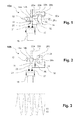
FIG. 1 shows a diagrammatic illustration of a first embodiment of a fluid valve,
FIG. 2 shows a diagrammatic illustration of a second embodiment of a fluid valve,
FIG. 3 shows a pressure profile diagram with respect to the embodiment according to FIG. 2,
FIG. 4 shows a diagrammatic illustration of a third embodiment of a fluid valve, and
FIG. 5 shows a pressure profile diagram with respect to the embodiment according to FIG. 4.
The first embodiment (shown diagrammatically in FIG. 1) of a fluid valve 10 a substantially comprises a valve body 12 which has two valve body sections 14 a, 14 b which bring about reversing of the fluid flow which flows from a fluid pump 16 via a non-return valve 17 and a fluid feed line 18 and back again via a fluid return line 20 and a further non-return valve 21. Accordingly, the fluid flow through the two flow lines 22 a, 22 b will take place either in one direction or in the other direction which is opposite with respect thereto.
The fluid valve 10 a comprises a reversing unit 24 which consists substantially of two chambers 28 a, 28 b which are separated from one another in a pressure-tight manner via a bistable surface element 26, preferably with the shape of a spherical cap. The two chambers 28 a, 28 b are connected via connecting lines 30 a, 30 b to the flow lines 22 a, 22 b.
A pressure pulse transmitter 32 which imparts a pressure pulse to the fluid feed line 18 is arranged in the fluid feed line 18. As an alternative to this, the pressure pulse can also be generated directly via the fluid pump if its design permits this. Proceeding from the position which is shown in FIG. 1, the pressure pulse which is generated by the pressure pulse transmitter 32 is transmitted via the fluid feed line 18, the valve body 12, the flow line 22 b, the connecting lines 30 b to the chamber 28 b. Since the other chamber 28 a does not experience the pressure pulse, the pressure difference over the surface element 26 rises, which leads to said surface element 26 snapping out of the position which is shown in FIG. 1 into a second stable position, in which the surface element 26 is folded over to the right. Via a connecting rod 34 which is fastened both to the surface element 26 and to the valve body 12, the latter is displaced into a second position, in which the flow paths are then reversed, that is to say the fluid feed line 18 is then connected to the flow line 22 a and the fluid return line 20 is connected to the flow line 22 b. In order to achieve switching back of the fluid valve 12, a pressure pulse is again transmitted from the pressure pulse transmitter 32 via the fluid feed line 18, the valve body 12, the flow line 22 a, the connecting lines 30 a to the chamber 28 a. Since the chamber 28 b does not experience the pressure pulse, the valve body 12 snaps back into the position which is shown in FIG. 1.
FIG. 2 diagrammatically shows a second embodiment of a fluid valve 10 b. Identical components have the same reference numerals as in FIG. 1. The fluid valve 10 b differs from the above-described fluid valve in that both chambers 28 a, 28 b are connected to the fluid feed line 18, to be precise one chamber 28 a is connected directly via the connecting line 30, with the result that pressure changes in the feed line 18 act directly in the chamber 28 a, and the other chamber 28 b is connected via a throttle 36, with the result that pressure pulses in the feed line 18 arrive in the chamber 28 b only with a time delay. In this embodiment, a switchover of the valve body 12 takes place at every pressure flank in the feed line 18. By way of suitable tuning of the pressure changing element, the switchover can also take place on account of modified pressure flanks by the fluid pump. This is shown in FIG. 3 as an exemplary pressure profile in the feed line 18 if a reciprocating piston pump 16 is used. If, starting from the position which is shown in FIG. 2, the falling pressure flank which is denoted by 40 in FIG. 3 occurs on the feed line 18, the falling pressure acts directly in the chamber 28 a which is connected directly to it. In contrast, the pressure in the chamber 28 b which is connected via the throttle 36 falls with a time delay, with the result that a pressure difference is built up which at some point brings about snapping over of the surface element 26. As a result, the valve body 12 is once again displaced via the connecting rod into the second position. In the reverse case, a rising pressure flank which is denoted by 42 in FIG. 3 leads to a direct pressure rise in the chamber 28 a and to a time-delayed pressure rise in the chamber 28 b, with the result that the surface element snaps back and moves the valve body 12 back into the position which is shown in FIG. 2 again.
FIG. 4 diagrammatically shows a third embodiment of a fluid valve 10 c. Identical components have the same reference numerals as in FIGS. 1 and 2. As in the embodiment of FIG. 2, in the case of the fluid valve 10 c, one chamber 28 b is connected via the connecting line 30 to the feed line 18, whereas the other chamber 28 b is connected via a resonance tube 44 to the feed line 18, the resonance tube being set to a resonant frequency which corresponds to the pulsing frequency of the fluid pump 16. During operation at the pulsing frequency, the fluid valve first of all remains in the position which is shown. If the fluid pump 16 is then stopped briefly, the pressure which is shown in FIG. 5 by means of line 46 remains high, while the resonance tube 44 continues to oscillate with the consequence that the pressure in the connected chamber 28 a continues to oscillate, as is shown by the dashed line 48. Since the pressure likewise remains high in the directly connected chamber 28 b, the result is a pressure difference in the two chambers 28 a, 28 b, which pressure difference leads to snapping over of the surface element 26.
If fluid is mentioned in conjunction with the invention, every largely incompressible fluid is meant, preferably hydraulic fluid.
LIST OF REFERENCE NUMERALS
  • 10 a, b, c Fluid valve
  • 12 Valve body
  • 14 a, b Valve body section
  • 16 Fluid pump
  • 18 Fluid feed line
  • 20 Fluid return line
  • 22 a, b Flow line
  • 24 Reversing unit
  • 26 Surface element
  • 28 a, b Chamber
  • 30 a, b Connecting line
  • 31 Pressure pulse transmitter
  • 34 Connecting rod
  • 36 Throttle
  • 40 Falling pressure flank
  • 42 Rising pressure flank
  • 44 Resonance tube
  • 46 Pressure profile, pump
  • 48 Pressure profile, resonance tube

Claims (6)

The invention claimed is:
1. Fluid valve arrangement having a bistable fluid valve for a fluid feed line and a fluid return line with a valve body which can be moved into two positions for two switching states, characterized in that a pressure pulse generator is provided for valve switchover in the feed line for switching over the fluid feed line and the fluid return line between two flow lines, and the fluid valve comprises a reversing unit which has two chambers which are separated from one another by a bistable surface element, the two chambers being connected to the two flow lines and the bistable surface element being operatively coupled to the valve body in order to actuate it.
2. Fluid valve arrangement according to claim 1, characterized in that the pressure pulse generator is formed by a reciprocating piston pump which is connected to the fluid valve arrangement.
3. Fluid valve arrangement according to claim 1, characterized in that the bistable surface element is configured in the form of a spherical cap.
4. Fluid valve arrangement having a bistable fluid valve for at least one fluid line with a valve body which can be moved into two positions for two switching states, characterized in that the fluid valve comprises a reversing unit which has two chambers which are separated from one another by a bistable surface element], one of the chambers communicating directly with the fluid line, whereas the other chamber is connected via a pressure changing member to the fluid line and the bistable surface element is operatively coupled to the valve body in order to actuate it.
5. Fluid valve arrangement according to claim 4, characterized in that the pressure changing member is a throttle point.
6. Fluid valve arrangement according to claim 4, characterized in that it is coupled to a fluid pump which operates in a pulsed manner, and one chamber is connected directly to the fluid line and the other chamber is connected via a resonance tube to the fluid line, the resonance tube being tuned to the frequency of the fluid pump.
US14/345,182 2011-09-15 2012-08-13 Fluid valve arrangement comprising a bistable fluid valve Active 2033-05-03 US9488196B2 (en)

Applications Claiming Priority (4)

Application Number Priority Date Filing Date Title
DE102011113361 2011-09-15
DE201110113361 DE102011113361B4 (en) 2011-09-15 2011-09-15 Fluid valve arrangement with a bistable fluid valve
DE102011113361.9 2011-09-15
PCT/DE2012/100237 WO2013037356A1 (en) 2011-09-15 2012-08-13 Fluid valve arrangement comprising a bistable fluid valve

Publications (2)

Publication Number Publication Date
US20140345267A1 US20140345267A1 (en) 2014-11-27
US9488196B2 true US9488196B2 (en) 2016-11-08

Family

ID=46924181

Family Applications (1)

Application Number Title Priority Date Filing Date
US14/345,182 Active 2033-05-03 US9488196B2 (en) 2011-09-15 2012-08-13 Fluid valve arrangement comprising a bistable fluid valve

Country Status (6)

Country Link
US (1) US9488196B2 (en)
EP (1) EP2756197B1 (en)
CN (1) CN103827511B (en)
DE (1) DE102011113361B4 (en)
ES (1) ES2572106T3 (en)
WO (1) WO2013037356A1 (en)

Cited By (1)

* Cited by examiner, † Cited by third party
Publication number Priority date Publication date Assignee Title
US12055236B2 (en) 2020-07-01 2024-08-06 BBG Baugeräte GmbH Switching means of working fluid

Families Citing this family (1)

* Cited by examiner, † Cited by third party
Publication number Priority date Publication date Assignee Title
CN110081039B (en) * 2019-04-28 2020-09-04 深圳市中粤海洋能源科技有限公司 Energy tracking valve group and modularized ocean current power generation system

Citations (6)

* Cited by examiner, † Cited by third party
Publication number Priority date Publication date Assignee Title
US3452779A (en) 1967-08-22 1969-07-01 Racine Hydraulics & Machinery Fluidic interface valve and control system
DE1600815A1 (en) 1966-02-01 1970-02-26 Ibm Pneumatic switching device, especially for low pressure systems
US5423244A (en) * 1990-11-21 1995-06-13 S.I.T.I. Societa Impianti Termoelettrici Industriali S.P.A. Hydraulic circuit for an apparatus for generating pressure and apparatus for generating pressure using said hydraulic circuit
WO1998012406A1 (en) 1996-09-20 1998-03-26 Trearc Ltd. Fluid actuators
US20050183770A1 (en) 2004-02-19 2005-08-25 Robert Metzinger Linear fluid drive system with detent
US20070044857A1 (en) 2005-08-31 2007-03-01 Festo Ag & Co. Pilot controlled pulse valve

Family Cites Families (3)

* Cited by examiner, † Cited by third party
Publication number Priority date Publication date Assignee Title
CN2162551Y (en) * 1992-09-30 1994-04-20 中国人民解放军运输工程学院 Direction control valve for pressure fluid
CN2238946Y (en) * 1995-06-29 1996-10-30 慈溪市燃气安全用具厂 Double steady-state gas electromagnet valve
CN1598376A (en) * 2004-08-19 2005-03-23 湖南泵阀制造有限公司 Adjustable reversing controlling valve

Patent Citations (7)

* Cited by examiner, † Cited by third party
Publication number Priority date Publication date Assignee Title
DE1600815A1 (en) 1966-02-01 1970-02-26 Ibm Pneumatic switching device, especially for low pressure systems
US3452779A (en) 1967-08-22 1969-07-01 Racine Hydraulics & Machinery Fluidic interface valve and control system
US5423244A (en) * 1990-11-21 1995-06-13 S.I.T.I. Societa Impianti Termoelettrici Industriali S.P.A. Hydraulic circuit for an apparatus for generating pressure and apparatus for generating pressure using said hydraulic circuit
WO1998012406A1 (en) 1996-09-20 1998-03-26 Trearc Ltd. Fluid actuators
US20050183770A1 (en) 2004-02-19 2005-08-25 Robert Metzinger Linear fluid drive system with detent
US20070044857A1 (en) 2005-08-31 2007-03-01 Festo Ag & Co. Pilot controlled pulse valve
EP1760376A1 (en) 2005-08-31 2007-03-07 FESTO AG & Co Pilot operated impulse valve

Non-Patent Citations (2)

* Cited by examiner, † Cited by third party
Title
Corresponding German Application No. 102011113361.9 Foreign Action dated Apr. 12, 2012.
Corresponding International Application No. PCT/DE2012/100237 Search Report dated Nov. 27, 2012.

Cited By (1)

* Cited by examiner, † Cited by third party
Publication number Priority date Publication date Assignee Title
US12055236B2 (en) 2020-07-01 2024-08-06 BBG Baugeräte GmbH Switching means of working fluid

Also Published As

Publication number Publication date
CN103827511A (en) 2014-05-28
DE102011113361A1 (en) 2013-03-21
US20140345267A1 (en) 2014-11-27
CN103827511B (en) 2016-06-15
WO2013037356A1 (en) 2013-03-21
EP2756197B1 (en) 2016-03-30
DE102011113361B4 (en) 2015-02-26
EP2756197A1 (en) 2014-07-23
ES2572106T3 (en) 2016-05-30

Similar Documents

Publication Publication Date Title
US9689407B2 (en) Hydraulic drive with rapid stroke and load stroke
US9488196B2 (en) Fluid valve arrangement comprising a bistable fluid valve
JP2017122454A (en) Apparatus using electronically controlled valves
KR20110013347A (en) Double Stage Reciprocating Pump
WO2008029288A3 (en) Fluid-powered proportioning pump and system for dispensing fluid inluding such a pump
WO2009029925A3 (en) Hydraulic flow control system
EP3239523A1 (en) Bellows pump apparatus
CN104329306B (en) A kind of hydraulic control system, method and pump
US11041510B2 (en) Hydraulic pressure amplifier arrangement
CA2996161A1 (en) Hydraulic pressure intensifier
RU2013126766A (en) METHOD, DEVICE AND SYSTEM FOR SWITCHING DOWNLOADING DIRECTIONS IN A PUMP UNIT
KR20140094325A (en) Bypass device for a main air ventilation of a pressure booster
CN104088827A (en) Hydraulic overturning device for pontoon bridge gangplank
CA2988146C (en) Hydraulic system and method of operating the same
CN102380239A (en) Vertical type filter press hydraulic system
EP2796727B1 (en) Dew condensation preventing valve
JP2016532828A (en) Hydraulic drive and method for discrete change of its position output
CN104903636B (en) Valve device and use of such a valve device
KR20160012425A (en) Method and apparatus for fuel switching
CN103573724B (en) Hydraulic circuit and using method thereof
CN102588172A (en) Injector
Hansen et al. Design of a multi-poppet on-off valve for wave energy converters
RU2228467C2 (en) Hydraulic system with emergency protection
KR101966955B1 (en) Universal reciprocal gas booster
KR101595982B1 (en) Micro Pump including hydrodynamic check valve

Legal Events

Date Code Title Description
AS Assignment

Owner name: EADS DEUTSCHLAND GMBH, GERMANY

Free format text: ASSIGNMENT OF ASSIGNORS INTEREST;ASSIGNORS:STORM, STEFAN;RAMMER, RAPHAEL;REEL/FRAME:032645/0510

Effective date: 20140220

STCF Information on status: patent grant

Free format text: PATENTED CASE

FEPP Fee payment procedure

Free format text: PAYOR NUMBER ASSIGNED (ORIGINAL EVENT CODE: ASPN); ENTITY STATUS OF PATENT OWNER: LARGE ENTITY

MAFP Maintenance fee payment

Free format text: PAYMENT OF MAINTENANCE FEE, 4TH YEAR, LARGE ENTITY (ORIGINAL EVENT CODE: M1551); ENTITY STATUS OF PATENT OWNER: LARGE ENTITY

Year of fee payment: 4

MAFP Maintenance fee payment

Free format text: PAYMENT OF MAINTENANCE FEE, 8TH YEAR, LARGE ENTITY (ORIGINAL EVENT CODE: M1552); ENTITY STATUS OF PATENT OWNER: LARGE ENTITY

Year of fee payment: 8