US9486933B2 - Band saw with emergency stop device - Google Patents
Band saw with emergency stop device Download PDFInfo
- Publication number
- US9486933B2 US9486933B2 US12/654,982 US65498210A US9486933B2 US 9486933 B2 US9486933 B2 US 9486933B2 US 65498210 A US65498210 A US 65498210A US 9486933 B2 US9486933 B2 US 9486933B2
- Authority
- US
- United States
- Prior art keywords
- brake member
- band saw
- retainer
- emergency stop
- arm
- Prior art date
- Legal status (The legal status is an assumption and is not a legal conclusion. Google has not performed a legal analysis and makes no representation as to the accuracy of the status listed.)
- Active, expires
Links
Images


Classifications
-
- B—PERFORMING OPERATIONS; TRANSPORTING
- B27—WORKING OR PRESERVING WOOD OR SIMILAR MATERIAL; NAILING OR STAPLING MACHINES IN GENERAL
- B27B—SAWS FOR WOOD OR SIMILAR MATERIAL; COMPONENTS OR ACCESSORIES THEREFOR
- B27B13/00—Band or strap sawing machines; Components or equipment therefor
- B27B13/14—Braking devices specially designed for band sawing machines, e.g. acting after damage of the band saw blade
-
- F—MECHANICAL ENGINEERING; LIGHTING; HEATING; WEAPONS; BLASTING
- F16—ENGINEERING ELEMENTS AND UNITS; GENERAL MEASURES FOR PRODUCING AND MAINTAINING EFFECTIVE FUNCTIONING OF MACHINES OR INSTALLATIONS; THERMAL INSULATION IN GENERAL
- F16D—COUPLINGS FOR TRANSMITTING ROTATION; CLUTCHES; BRAKES
- F16D59/00—Self-acting brakes, e.g. coming into operation at a predetermined speed
- F16D59/02—Self-acting brakes, e.g. coming into operation at a predetermined speed spring-loaded and adapted to be released by mechanical, fluid, or electromagnetic means
-
- F—MECHANICAL ENGINEERING; LIGHTING; HEATING; WEAPONS; BLASTING
- F16—ENGINEERING ELEMENTS AND UNITS; GENERAL MEASURES FOR PRODUCING AND MAINTAINING EFFECTIVE FUNCTIONING OF MACHINES OR INSTALLATIONS; THERMAL INSULATION IN GENERAL
- F16P—SAFETY DEVICES IN GENERAL; SAFETY DEVICES FOR PRESSES
- F16P1/00—Safety devices independent of the control and operation of any machine
-
- F—MECHANICAL ENGINEERING; LIGHTING; HEATING; WEAPONS; BLASTING
- F16—ENGINEERING ELEMENTS AND UNITS; GENERAL MEASURES FOR PRODUCING AND MAINTAINING EFFECTIVE FUNCTIONING OF MACHINES OR INSTALLATIONS; THERMAL INSULATION IN GENERAL
- F16P—SAFETY DEVICES IN GENERAL; SAFETY DEVICES FOR PRESSES
- F16P7/00—Emergency devices preventing damage to a machine or apparatus
- F16P7/02—Emergency devices preventing damage to a machine or apparatus by causing the machine to stop on the occurrence of dangerous conditions therein
-
- F—MECHANICAL ENGINEERING; LIGHTING; HEATING; WEAPONS; BLASTING
- F16—ENGINEERING ELEMENTS AND UNITS; GENERAL MEASURES FOR PRODUCING AND MAINTAINING EFFECTIVE FUNCTIONING OF MACHINES OR INSTALLATIONS; THERMAL INSULATION IN GENERAL
- F16D—COUPLINGS FOR TRANSMITTING ROTATION; CLUTCHES; BRAKES
- F16D2127/00—Auxiliary mechanisms
- F16D2127/001—Auxiliary mechanisms for automatic or self-acting brake operation
-
- Y—GENERAL TAGGING OF NEW TECHNOLOGICAL DEVELOPMENTS; GENERAL TAGGING OF CROSS-SECTIONAL TECHNOLOGIES SPANNING OVER SEVERAL SECTIONS OF THE IPC; TECHNICAL SUBJECTS COVERED BY FORMER USPC CROSS-REFERENCE ART COLLECTIONS [XRACs] AND DIGESTS
- Y10—TECHNICAL SUBJECTS COVERED BY FORMER USPC
- Y10T—TECHNICAL SUBJECTS COVERED BY FORMER US CLASSIFICATION
- Y10T83/00—Cutting
- Y10T83/081—With randomly actuated stopping means
- Y10T83/088—Responsive to tool detector or work-feed-means detector
- Y10T83/089—Responsive to tool characteristic
-
- Y—GENERAL TAGGING OF NEW TECHNOLOGICAL DEVELOPMENTS; GENERAL TAGGING OF CROSS-SECTIONAL TECHNOLOGIES SPANNING OVER SEVERAL SECTIONS OF THE IPC; TECHNICAL SUBJECTS COVERED BY FORMER USPC CROSS-REFERENCE ART COLLECTIONS [XRACs] AND DIGESTS
- Y10—TECHNICAL SUBJECTS COVERED BY FORMER USPC
- Y10T—TECHNICAL SUBJECTS COVERED BY FORMER US CLASSIFICATION
- Y10T83/00—Cutting
- Y10T83/707—By endless band or chain knife
- Y10T83/7226—With means to guard the tension
-
- Y—GENERAL TAGGING OF NEW TECHNOLOGICAL DEVELOPMENTS; GENERAL TAGGING OF CROSS-SECTIONAL TECHNOLOGIES SPANNING OVER SEVERAL SECTIONS OF THE IPC; TECHNICAL SUBJECTS COVERED BY FORMER USPC CROSS-REFERENCE ART COLLECTIONS [XRACs] AND DIGESTS
- Y10—TECHNICAL SUBJECTS COVERED BY FORMER USPC
- Y10T—TECHNICAL SUBJECTS COVERED BY FORMER US CLASSIFICATION
- Y10T83/00—Cutting
- Y10T83/849—With signal, scale, or indicator
- Y10T83/85—Signal; e.g., alarm
Definitions
- the present invention relates generally to band saws and more particularly, to an emergency stop device for use in cooperation with a band saw for urging and stopping a running drive or follower wheel around which an endless band saw blade is looped.
- FIG. 1 shows a conventional band saw 10 comprising mainly a drive wheel 12 directly connected with an output shaft 13 of a motor (not shown in the drawing), and a follower wheel 14 driven by the drive wheel 12 through an endless band saw blade 16 , which is tensionally looped around the drive wheel 12 and the follower wheel 14 .
- the motor When the motor is started, it will drive the drive wheel 12 to rotate, which in turn drives the band saw blade 16 to rotate the follower wheel 14 .
- a workpiece is placed on the worktable and pushed toward an exposed cutting portion 162 of the running band saw blade 16 for cutting. Since the running cutting portion 162 is exposed to ambient environment, the band saw 10 shall be operated carefully; otherwise, severe injury may occur to the operator.
- the conventional band saw is always equipped with kinds of an emergency stop device.
- a well-known emergency stop mechanism adopted by the conventional band saw 10 includes an emergency stop button (not shown) electrically connected with the motor for an emergency shutting down the power of the motor that drives the drive wheel 12 .
- an emergency stop button (not shown) electrically connected with the motor for an emergency shutting down the power of the motor that drives the drive wheel 12 .
- the drive wheel 12 and the follower wheel 14 which have great mass and will gain great angular momentum when they are rotating, won't stop running immediately after the power of the motor is shut down, resulting in that the cutting motion of the band saw blade 16 will continue for a while after the motor is power-off.
- the present invention has been accomplished in view of the above-noted circumstances. It is an objective of the present invention to provide an emergency stop device that can stop the cutting motion of the band saw blade immediately after the motor is power-off for lowering the possibility of damage when the band saw is in the emergency situation.
- the emergency stop device for a band saw for stopping a running wheel of the band saw, around which a band saw blade is looped comprises a brake member, a spring member and a retainer.
- the brake member is moveable between a standby position where the brake member is spaced apart from the running wheel of the band saw, and an active position where the brake member firmly urges and stops the running wheel of the band saw.
- the spring member exerts a force on the brake member tending to move the brake member from the standby position toward the active position.
- the retainer is moveable between an engaged position where the retainer is engageable with the brake member to hold the brake member at the standby position, and a released position where the retainer is released apart from the brake member for enabling the brake member to move to the active position by the actuation of the spring member.
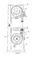
- FIG. 1 is a schematic drawing showing a band saw of a prior art
- FIG. 2 is a top plan view of the emergency stop device in accordance with a preferred embodiment of the present invention.
- FIG. 3 is a sectional view taken along line 3 - 3 of FIG. 2 , showing that the emergency stop device is inactive;
- FIG. 4 is similar to FIG. 3 , but showing that the emergency stop device is in action at a beginning stage;
- FIG. 5 is a schematic drawing showing that the emergency stop device in accordance with the preferred embodiment of the present invention is installed at a place in proximity to a follower wheel of a band saw;
- FIG. 6 is similar to FIG. 4 , but showing that the emergency stop device is in action at a final stage;
- FIG. 7 is a schematic drawing showing that the emergency stop device in accordance with the preferred embodiment of the present invention is installed at a place in proximity to a right top side of a drive wheel of a band saw, and
- FIG. 8 is a schematic drawing showing that the emergency stop device in accordance with the preferred embodiment of the present invention is installed at a place in proximity to a left top side of a drive wheel of a band saw.
- an emergency stop device 20 in accordance with a preferred embodiment of the present invention comprises a bracket 30 , a controller 40 disposed inside the bracket 30 , a retainer 50 , a spring member 60 , a brake member 70 and two guides 80 .
- the bracket 30 has a flat bottom 32 , a slanted top opening 34 and a passage 36 at a left side thereof for the passing of an endless band saw blade 94 .
- the controller 40 is realized by using an electromagnetic switch, which includes a housing 44 mounted inside the bracket 30 , and an axially moveable rod 42 protruding out of the housing 44 and having a head 422 moveable along with the rod 42 relative to the housing 44 between a retracted position P 1 , as shown in FIG. 3 , and an extended position P 2 , as shown in FIG. 4 .
- an electromagnetic switch which includes a housing 44 mounted inside the bracket 30 , and an axially moveable rod 42 protruding out of the housing 44 and having a head 422 moveable along with the rod 42 relative to the housing 44 between a retracted position P 1 , as shown in FIG. 3 , and an extended position P 2 , as shown in FIG. 4 .
- the electromagnetic switch of the controller 40 is power-off, the head 422 of the axially moveable rod 42 is kept at the retracted position P 1 , as shown in FIG. 3 .
- the head 422 of the axially moveable rod 42 is moved by a magnetic force that exerts a force on the axially moveable rod 42 in a direction away from the housing 44 and eventually stopped at the extended position P 2 , as shown in FIG. 4 .
- the head 422 of the axially moveable rod 42 will still stay at the extended position P 2 ; however, the head 422 of the axially moveable rod 42 can be moved back to the retracted position P 1 if an appropriate external force is exerted on the axially moveable rod 42 .
- the retainer 50 is realized in this preferred embodiment by using a lever having a first arm 52 , a second arm 54 disposed at a right angle relative to the first arm 52 and provided at a free end thereof with a hook 542 , and a pivot portion 56 disposed between the first and second arms 52 and 54 and pivotally connected with a pivot shaft 562 mounted inside the bracket 30 .
- a torsion spring 58 is sleeved on the pivot shaft 562 .
- One end of the torsion spring 58 is supported at a part of the bracket 30 and the other end of the torsion spring 58 is supported at the first arm 52 .
- the free end of the first arm 52 is contacted with and pushable by the head 422 of the axially moveable rod 42 of controller 40 , such that the retainer 50 is pivotally moveable about the pivot portion 56 thereof by the actuation of the axially moveable rod 42 .
- the second arm 54 of the retainer 50 is kept at an engaged position P 3 where the hook 542 of the retainer 50 is engageable with the brake member 70 , as shown in FIG. 3 .
- the torsion spring 58 is untwisted and kept in the normal configuration.
- the retainer 50 will be forced to clockwisely turn about the pivot shaft 562 , such that the second arm 54 of the retainer 50 will be biased to a released position P 4 where the hook 542 of the retainer 50 is separatable apart from the brake member 70 , as shown in FIG. 4 .
- the torsion spring 58 is twisted to induce a rebound force exerting on the retainer 50 for turning the retainer 50 counterclockwise.
- the second arm 54 will be biased back to the engaged position P 3 along with the counterclockwise rotation of the retainer 50 and the head 422 of the rod 42 can be moved from the extended position P 2 back to the retracted position P 1 by the push of the free end of the first arm 52 of the retainer 50 .
- the spring member 60 is realized by using a compression spring 60 , which is sleeved on a guide rod 66 mounted to the bottom 32 of the bracket 30 , and provided with a fixed end 62 fixedly mounted to the bottom 32 of the bracket 30 , and a moveable end 64 moveable between a first compressed position P 5 where the compression spring 60 is approximately fully compressed as shown in FIG. 3 , and a second compression position P 6 where the compression spring 60 is slightly compressed as shown in FIG. 4 .
- the brake member 70 has a relatively narrower top surface 71 , a relatively wider bottom surface 72 , a slantingly inwardly curved stop surface 73 , a cylindrical recess 74 recessed vertically from the bottom surface 72 toward the stop surface 73 , and a guide slot 75 cut through front and rear surfaces 76 and 77 of the brake member 70 and divided into a relatively narrower portion 752 and a relatively wider portion 754 .
- On the front surface 76 a notch 78 and a locating groove 79 are recessed.
- the notch 78 extends upwardly from the bottom surface 72 to the bottom end of the relatively wider portion 754 of the guide slot 75 and has a beveled cut 782 at an entrance thereof.
- the locating groove 79 extends transversely from a left side of the brake member 70 to a middle of the relatively wider portion 754 of the guide slot 75 .
- the moveable end 64 of the spring member 60 is disposed inside the cylindrical recess 74 .
- the guides 80 are rounded posts having a diameter proximately equal to the width of the relatively narrower portion 752 of the guide slot 75 .
- the guides 80 are protrudently and spacedly mounted on the bracket 30 and located in the guide slot 75 .
- the emergency stop device 20 is used in cooperation with a band saw 90 in which the bracket 30 is mounted.
- the band saw 90 includes two wheels, namely a drive wheel 92 directly connected to an output shaft of a motor (not shown in the drawings), and a follower wheel 96 which is driven by the drive wheel 92 through the endless band saw blade 94 looping around the drive and follower wheels 92 and 96 .
- the emergency stop device 20 is mounted at a location of the band saw 90 , which is in proximity to the contact place where the blade 94 contacts the circumference 962 of the follower wheel 96 , in such a way that the blade 94 runs through the passage 36 of the bracket 30 , the top surface 71 of the brake member 70 is aimed at the contact place, and the stop surface 73 of the brake member 70 is aimed at the circumference 962 of the follower wheel 96 .
- the brake member 70 stays at the standby position P 7 and compresses the spring member 60 to keep the moveable end 64 of the spring member 60 at the first compressed position P 5 , and the second arm 54 passes through the notch 78 to have the hook 542 be hooked on the locating groove 79 so as to firmly hold the brake member 70 at the standby position P 7 and keep the moveable end 64 of the spring member 60 motionless.
- the guides 80 are located in the relatively narrower portion 752 of the guide slot 75 to prohibit any transverse movement of the brake member 70 .
- the emergency stop device 20 is set apart from the follower wheel 96 , such that the band saw 90 can run normally.
- the emergency stop device 20 of the present invention can be started by pushing an emergency stop button (not shown in the drawings) that is electrically connected with the controller 40 to power on the controller 40 .
- an emergency stop button (not shown in the drawings) that is electrically connected with the controller 40 to power on the controller 40 .
- the electromagnetic switch of the controller 40 is power-on, as shown in FIG. 4 , the second arm 54 of the retainer 50 will be moved to the released position P 4 , i.e.
- the hook 542 of the second arm 54 will be released away from the locating groove 79 of the brake member 70 , and thereafter the moveable end 64 of the spring member 60 will push the brake member 70 to move upwardly, such that the brake member 70 will be moved across the top opening 34 of the bracket 30 to the active position P 8 where the brake member 70 urges against the running follower wheel 96 .
- the relatively narrower portion 752 of the guide slot 75 will leave the guides 80 and the relatively wider portion 754 of the guide slot 75 will approach and reach the guides 80 , such that a transverse gap may exist between the guides 80 and the periphery of the relatively wider portion 754 , which allows the brake member 70 to move transversely.
- the curved stop surface 73 of the brake member 70 will contact the circumference 962 of the running follower wheel 96 , and then the brake member 70 will move transversely, and eventually be jammed between the running follower wheel 96 and the periphery wall that defines the passage 36 such that the curved stop surface 73 will firmly urge the circumference 962 of the running follower wheel 96 to stop the running of the follower wheel 96 so as to further stop the cutting motion of the band saw blade 94 .
- a limit switch 22 mounted adjacent to the controller 40 will be simultaneously started by the controller 40 for enabling the band saw 90 to raise a malfunction alarm notifying ambient people.
- FIG. 6 shows that the emergency stop device 20 is started after a predetermined period of time, in which the electromagnetic switch of the controller 40 is power-off, such that second arm 54 of the retainer 50 is swiveled back to the initial position, which is the same as the engaged position P 3 but not engaged with the brake member 70 because the brake member 70 has been moved to the active position P 8 .
- the user wants to reset the emergency stop device 20 , the user can apply an external force on the brake member 70 to move the brake member 70 back to the standby position P 7 from the active position P 8 and to compress the spring member 60 to make the moveable end 64 of the spring member 64 move back to the first compressed position P 5 from the second compressed position P 6 .
- the beveled cut 782 of the notch 78 of the brake member 70 will contact the slanted top surface of the hook 542 and then slightly push the hook 542 away for enabling the second arm 54 to be inserted inside the brake member 70 through the notch 78 when the brake member 70 is kept moving, and finally the hook 542 will move back due to the rebound force of the torsion spring 58 and hook on the locating groove 79 to keep the brake member 70 at the standby position P 7 .
- the emergency stop device 20 of the present invention is installed in the band saw 90 in proximity to the running follower wheel 96 .
- the emergency stop device 20 can be installed at any appropriate position in proximity to the running follower or drive wheel 96 or 92 as along as the brake member 70 can be jammed between the periphery wall that defines the passage 36 and the follower wheel 96 or the drive wheel 92 , wherein the curved stop surface 73 is firmly stopped against the circumference of the follower wheel 96 or the drive wheel 92 .
- FIG. 7 shows that the emergency stop device 20 is installed at a location in proximity to a place where the blade 94 contacts the circumference of the drive wheel 92 .
- the brake member 70 will firmly urge against the drive wheel 92 to stop running of the drive wheel 92 so as to stop the cutting motion of the band saw blade 94 .
- the blade 94 may not run through the passage 36 .
- FIG. 8 shows that the emergency stop device 20 is installed at a location in proximity to a left top side of the drive wheel 92 in such a way that the blade 94 doesn't run through the passage 36 .
- the running drive wheel 92 can be stopped by the brake member 70 .
Abstract
An emergency stop device for a band saw includes a brake member moveable between a standby position and an active position where the brake member firmly urges and stops a running wheel of the band saw, around which a band saw blade is looped. The brake member is held by a retainer at the standby position when the emergency stop device is inactive. When the emergency stop device is started, the retainer is separated apart from the brake member for enabling the brake member to move by an actuation of a spring member from the standby position to the active position so as to stop the cutting motion of the band saw blade.
Description
1. Field of the Invention
The present invention relates generally to band saws and more particularly, to an emergency stop device for use in cooperation with a band saw for urging and stopping a running drive or follower wheel around which an endless band saw blade is looped.
2. Description of the Related Art
A well-known emergency stop mechanism adopted by the conventional band saw 10 includes an emergency stop button (not shown) electrically connected with the motor for an emergency shutting down the power of the motor that drives the drive wheel 12. However, because of the law of inertia, the drive wheel 12 and the follower wheel 14, which have great mass and will gain great angular momentum when they are rotating, won't stop running immediately after the power of the motor is shut down, resulting in that the cutting motion of the band saw blade 16 will continue for a while after the motor is power-off. In light of this, it is desired to have an improved emergency stop device that can stop the cutting motion of the band saw blade immediately after the motor that drives the drive wheel is power-off.
The present invention has been accomplished in view of the above-noted circumstances. It is an objective of the present invention to provide an emergency stop device that can stop the cutting motion of the band saw blade immediately after the motor is power-off for lowering the possibility of damage when the band saw is in the emergency situation.
To achieve the objective of the present invention, the emergency stop device for a band saw for stopping a running wheel of the band saw, around which a band saw blade is looped, comprises a brake member, a spring member and a retainer. The brake member is moveable between a standby position where the brake member is spaced apart from the running wheel of the band saw, and an active position where the brake member firmly urges and stops the running wheel of the band saw. The spring member exerts a force on the brake member tending to move the brake member from the standby position toward the active position. The retainer is moveable between an engaged position where the retainer is engageable with the brake member to hold the brake member at the standby position, and a released position where the retainer is released apart from the brake member for enabling the brake member to move to the active position by the actuation of the spring member. As a result, when the band saw equipped with the emergency stop device of the present invention is working normally, the brake member is held by the retainer at the standby position. When the running band saw needs to be emergency-stopped, the emergency stop device can be started by the user to control the retainer to be separated apart from the brake member for enabling the brake member to stop the running wheel so as to further stop the cutting motion of the band saw blade.
Further scope of applicability of the present invention will become apparent from the detailed description given hereinafter. However, it should be understood that the detailed description and specific examples, while indicating preferred embodiments of the invention, are given by way of illustration only, since various changes and modifications within the spirit and scope of the invention will become apparent to those skilled in the art from this detailed description.
The present invention will become more fully understood from the detailed description given herein below and the accompanying drawings which are given by way of illustration only, and thus are not limitative of the present invention, and wherein:
As shown in FIGS. 2-4 , an emergency stop device 20 in accordance with a preferred embodiment of the present invention comprises a bracket 30, a controller 40 disposed inside the bracket 30, a retainer 50, a spring member 60, a brake member 70 and two guides 80.
The bracket 30 has a flat bottom 32, a slanted top opening 34 and a passage 36 at a left side thereof for the passing of an endless band saw blade 94.
In the preferred embodiment of the present invention, the controller 40 is realized by using an electromagnetic switch, which includes a housing 44 mounted inside the bracket 30, and an axially moveable rod 42 protruding out of the housing 44 and having a head 422 moveable along with the rod 42 relative to the housing 44 between a retracted position P1, as shown in FIG. 3 , and an extended position P2, as shown in FIG. 4 . Specifically speaking, when the electromagnetic switch of the controller 40 is power-off, the head 422 of the axially moveable rod 42 is kept at the retracted position P1, as shown in FIG. 3 . In case the electromagnetic switch of the controller 40 is power-on, the head 422 of the axially moveable rod 42 is moved by a magnetic force that exerts a force on the axially moveable rod 42 in a direction away from the housing 44 and eventually stopped at the extended position P2, as shown in FIG. 4 . At this moment, even if the electromagnetic switch of the controller 40 is turned off, the head 422 of the axially moveable rod 42 will still stay at the extended position P2; however, the head 422 of the axially moveable rod 42 can be moved back to the retracted position P1 if an appropriate external force is exerted on the axially moveable rod 42.
The retainer 50 is realized in this preferred embodiment by using a lever having a first arm 52, a second arm 54 disposed at a right angle relative to the first arm 52 and provided at a free end thereof with a hook 542, and a pivot portion 56 disposed between the first and second arms 52 and 54 and pivotally connected with a pivot shaft 562 mounted inside the bracket 30. A torsion spring 58 is sleeved on the pivot shaft 562. One end of the torsion spring 58 is supported at a part of the bracket 30 and the other end of the torsion spring 58 is supported at the first arm 52. The free end of the first arm 52 is contacted with and pushable by the head 422 of the axially moveable rod 42 of controller 40, such that the retainer 50 is pivotally moveable about the pivot portion 56 thereof by the actuation of the axially moveable rod 42. Specifically speaking, when the head 422 of the axially moveable rod 42 stays at the retracted position P1, the second arm 54 of the retainer 50 is kept at an engaged position P3 where the hook 542 of the retainer 50 is engageable with the brake member 70, as shown in FIG. 3 . At this moment, the torsion spring 58 is untwisted and kept in the normal configuration. On the other hand, in case the head 422 of the rod 42 is moved from the retracted position P1 to the extended position P2 to push the free end of the first arm 52 of the retainer 50 to move, the retainer 50 will be forced to clockwisely turn about the pivot shaft 562, such that the second arm 54 of the retainer 50 will be biased to a released position P4 where the hook 542 of the retainer 50 is separatable apart from the brake member 70, as shown in FIG. 4 . At this moment, the torsion spring 58 is twisted to induce a rebound force exerting on the retainer 50 for turning the retainer 50 counterclockwise. As a result, when the electromagnetic switch of the controller 40 is turned power-off, the second arm 54 will be biased back to the engaged position P3 along with the counterclockwise rotation of the retainer 50 and the head 422 of the rod 42 can be moved from the extended position P2 back to the retracted position P1 by the push of the free end of the first arm 52 of the retainer 50.
The spring member 60 is realized by using a compression spring 60, which is sleeved on a guide rod 66 mounted to the bottom 32 of the bracket 30, and provided with a fixed end 62 fixedly mounted to the bottom 32 of the bracket 30, and a moveable end 64 moveable between a first compressed position P5 where the compression spring 60 is approximately fully compressed as shown in FIG. 3 , and a second compression position P6 where the compression spring 60 is slightly compressed as shown in FIG. 4 .
The brake member 70 has a relatively narrower top surface 71, a relatively wider bottom surface 72, a slantingly inwardly curved stop surface 73, a cylindrical recess 74 recessed vertically from the bottom surface 72 toward the stop surface 73, and a guide slot 75 cut through front and rear surfaces 76 and 77 of the brake member 70 and divided into a relatively narrower portion 752 and a relatively wider portion 754. On the front surface 76, a notch 78 and a locating groove 79 are recessed. The notch 78 extends upwardly from the bottom surface 72 to the bottom end of the relatively wider portion 754 of the guide slot 75 and has a beveled cut 782 at an entrance thereof. The locating groove 79 extends transversely from a left side of the brake member 70 to a middle of the relatively wider portion 754 of the guide slot 75. In addition, the moveable end 64 of the spring member 60 is disposed inside the cylindrical recess 74. When the moveable end 64 of the spring member 60 is moved from the first compressed position P5 to the second compressed position P6, the rebound force of the spring member 60 will act on the brake member 70 to move the brake member 70 from a standby position P7, as shown in FIG. 3 , to an active position P8, as shown in FIG. 4 .
The guides 80 are rounded posts having a diameter proximately equal to the width of the relatively narrower portion 752 of the guide slot 75. The guides 80 are protrudently and spacedly mounted on the bracket 30 and located in the guide slot 75.
Detailed description of how the above-mentioned elements of the emergency stop device 20 of the present invention will be given hereunder.
As shown in FIGS. 3 and 5 , the emergency stop device 20 is used in cooperation with a band saw 90 in which the bracket 30 is mounted. Normally, the band saw 90 includes two wheels, namely a drive wheel 92 directly connected to an output shaft of a motor (not shown in the drawings), and a follower wheel 96 which is driven by the drive wheel 92 through the endless band saw blade 94 looping around the drive and follower wheels 92 and 96. The emergency stop device 20 is mounted at a location of the band saw 90, which is in proximity to the contact place where the blade 94 contacts the circumference 962 of the follower wheel 96, in such a way that the blade 94 runs through the passage 36 of the bracket 30, the top surface 71 of the brake member 70 is aimed at the contact place, and the stop surface 73 of the brake member 70 is aimed at the circumference 962 of the follower wheel 96.
As shown in FIG. 3 , when the emergency stop device 20 is inactive, the brake member 70 stays at the standby position P7 and compresses the spring member 60 to keep the moveable end 64 of the spring member 60 at the first compressed position P5, and the second arm 54 passes through the notch 78 to have the hook 542 be hooked on the locating groove 79 so as to firmly hold the brake member 70 at the standby position P7 and keep the moveable end 64 of the spring member 60 motionless. At this moment, the guides 80 are located in the relatively narrower portion 752 of the guide slot 75 to prohibit any transverse movement of the brake member 70. As a result, the emergency stop device 20 is set apart from the follower wheel 96, such that the band saw 90 can run normally.
When the band saw 90 needs to be emergency-stopped, the emergency stop device 20 of the present invention can be started by pushing an emergency stop button (not shown in the drawings) that is electrically connected with the controller 40 to power on the controller 40. As soon as the electromagnetic switch of the controller 40 is power-on, as shown in FIG. 4 , the second arm 54 of the retainer 50 will be moved to the released position P4, i.e. the hook 542 of the second arm 54 will be released away from the locating groove 79 of the brake member 70, and thereafter the moveable end 64 of the spring member 60 will push the brake member 70 to move upwardly, such that the brake member 70 will be moved across the top opening 34 of the bracket 30 to the active position P8 where the brake member 70 urges against the running follower wheel 96. During the upward movement of the brake member 70, the relatively narrower portion 752 of the guide slot 75 will leave the guides 80 and the relatively wider portion 754 of the guide slot 75 will approach and reach the guides 80, such that a transverse gap may exist between the guides 80 and the periphery of the relatively wider portion 754, which allows the brake member 70 to move transversely. In the process of movement of the brake member 70 from the standby position P7 to the active position P8, the curved stop surface 73 of the brake member 70 will contact the circumference 962 of the running follower wheel 96, and then the brake member 70 will move transversely, and eventually be jammed between the running follower wheel 96 and the periphery wall that defines the passage 36 such that the curved stop surface 73 will firmly urge the circumference 962 of the running follower wheel 96 to stop the running of the follower wheel 96 so as to further stop the cutting motion of the band saw blade 94. On the other hand, when the controller 40 is power-on, a limit switch 22 mounted adjacent to the controller 40 will be simultaneously started by the controller 40 for enabling the band saw 90 to raise a malfunction alarm notifying ambient people.
In the above-mentioned embodiment, the emergency stop device 20 of the present invention is installed in the band saw 90 in proximity to the running follower wheel 96. However, it is to be noted that the emergency stop device 20 can be installed at any appropriate position in proximity to the running follower or drive wheel 96 or 92 as along as the brake member 70 can be jammed between the periphery wall that defines the passage 36 and the follower wheel 96 or the drive wheel 92, wherein the curved stop surface 73 is firmly stopped against the circumference of the follower wheel 96 or the drive wheel 92. For example, FIG. 7 shows that the emergency stop device 20 is installed at a location in proximity to a place where the blade 94 contacts the circumference of the drive wheel 92. As soon as the emergency stop device 20 is started, the brake member 70 will firmly urge against the drive wheel 92 to stop running of the drive wheel 92 so as to stop the cutting motion of the band saw blade 94. In addition, depending on the location at which the emergency stop device 20 is installed, the blade 94 may not run through the passage 36. For example, FIG. 8 shows that the emergency stop device 20 is installed at a location in proximity to a left top side of the drive wheel 92 in such a way that the blade 94 doesn't run through the passage 36. Similarly, as soon as the emergency stop device 20 is started, the running drive wheel 92 can be stopped by the brake member 70.
The invention being thus described, it will be obvious that the same may be varied in many ways. Such variations are not to be regarded as a departure from the spirit and scope of the invention, and all such modifications as would be obvious to one skilled in the art are intended to be included within the scope of the following claims.
Claims (8)
1. A band saw comprising a running wheel, around which a band saw blade is looped, and an emergency stop device for stopping the running wheel, said emergency stop device comprising:
a bracket having a bottom portion, a top portion, a side portion and a passage formed at the side portion, the passage being defined by a plurality of side walls, the band saw blade passing through the passage;
a brake member supported by said bracket and positioned proximate to the running wheel of the band saw such that the brake member is moveable between a standby position for positioning the brake member spaced apart from the running wheel of the band saw, and an active position for positioning the brake member between the passage and the running wheel in a manner that the brake member is firmly urged against both the running wheel and one of the side walls for stopping of the running wheel, the brake member comprising a locating groove, a distal end, a curved stop surface, an abutting surface and a tapering section, the tapering section being located between the curved stop surface and the abutting surface, the tapering section being tapered off toward the distal end; the curved stop surface being abutted against the running wheel and the abutting surface being abutted against the one of the side walls when the brake member is in the active position;
a spring member exerting a force on the brake member tending to move the brake member from the standby position toward the active position;
a retainer moveable between an engaged position where the retainer is engaged with the brake member to hold the brake member at the standby position, and a released position where the retainer is released apart from the brake member for enabling the brake member to move to the active position by the actuation of the spring member, the retainer comprising a hook, a first arm, a second arm provided at a free end thereof with the hook, and a pivot portion between the first arm and the second arm, the hook being configured to be hooked on the locating groove of the brake member when the brake member stays at the standby position and the retainer stays at the engaged position, the retainer is pivotally moveable about the pivot portion between the engaged position and the released position; and
a controller, the controller is an electromagnetic switch having an axially moveable rod pushable on the first arm of the retainer for pivotally moving the retainer from the engaged position to the released position;
wherein when the emergency stop device is active, the controller is powered such that the moveable rod pushes the first arm of the retainer and thus the second arm of the retainer is moved from the engaged position to the released position, and the hook is released away from the locating groove of the brake member, and thereafter the spring member pushes the brake member to move toward the active position, the brake member stays at the active position before an external force is manually applied thereon to move the brake member back to the standby position.
2. The band saw of claim 1 , wherein the spring member has a fixed end and a moveable end, the movable end being connected with the brake member.
3. The band saw of claim 2 , wherein the fixed end of the spring member is fixedly mounted to the bracket.
4. The band saw of claim 1 , wherein the pivot portion of the retainer is pivotally connected to the bracket.
5. The band saw of claim 1 , wherein the pivot portion of the retainer is mounted with a torsion spring for exerting a force on the retainer tending to move the retainer to the engaged position.
6. The band saw of claim 1 , further comprising a guide; wherein the brake member comprises a guide slot in which the guide is located for guiding movement of the brake member.
7. The band saw of claim 6 , wherein the guide is mounted on the bracket.
8. The band saw of claim 6 , wherein the guide slot has a relatively narrower portion and a relatively wider portion; the guide is located in the relatively narrower portion of the guide slot when the brake member stays at the standby position, and the guide is located in the relatively wider portion of the guide slot when the brake member stays at the active position.
Priority Applications (1)
| Application Number | Priority Date | Filing Date | Title |
|---|---|---|---|
| US12/654,982 US9486933B2 (en) | 2010-01-12 | 2010-01-12 | Band saw with emergency stop device |
Applications Claiming Priority (1)
| Application Number | Priority Date | Filing Date | Title |
|---|---|---|---|
| US12/654,982 US9486933B2 (en) | 2010-01-12 | 2010-01-12 | Band saw with emergency stop device |
Publications (2)
| Publication Number | Publication Date |
|---|---|
| US20110167974A1 US20110167974A1 (en) | 2011-07-14 |
| US9486933B2 true US9486933B2 (en) | 2016-11-08 |
Family
ID=44257472
Family Applications (1)
| Application Number | Title | Priority Date | Filing Date |
|---|---|---|---|
| US12/654,982 Active 2032-02-11 US9486933B2 (en) | 2010-01-12 | 2010-01-12 | Band saw with emergency stop device |
Country Status (1)
| Country | Link |
|---|---|
| US (1) | US9486933B2 (en) |
Families Citing this family (3)
| Publication number | Priority date | Publication date | Assignee | Title |
|---|---|---|---|---|
| US10695938B2 (en) * | 2014-09-18 | 2020-06-30 | Scott Automation & Robotics Pty Ltd. | Safety apparatus for protecting an operator of an electrically powered saw |
| FR3072039B1 (en) * | 2017-10-09 | 2019-11-08 | Aumatech | SAFETY DEVICE FOR A BAND SAW |
| EP3974111A1 (en) * | 2020-09-25 | 2022-03-30 | Andreas Stihl AG & Co. KG | Handheld tool and method for operating a handheld tool |
Citations (24)
| Publication number | Priority date | Publication date | Assignee | Title |
|---|---|---|---|---|
| US586745A (en) * | 1897-07-20 | Island | ||
| US1684815A (en) * | 1928-09-18 | Bone saw | ||
| US1757785A (en) * | 1928-06-02 | 1930-05-06 | Charles E Sullenberger | Band sawing machine |
| US1927203A (en) * | 1932-12-02 | 1933-09-19 | Tannewitz Works | Brake device for band saws |
| US1946758A (en) * | 1931-08-19 | 1934-02-13 | Powell Stanley | Brake |
| US2177961A (en) * | 1939-01-28 | 1939-10-31 | Westinghouse Air Brake Co | Brake mechanism |
| US2389376A (en) * | 1941-03-18 | 1945-11-20 | Mandin Sven Gustaf Adolf | Means for cutting off towing cables and the like |
| US2660636A (en) * | 1951-07-05 | 1953-11-24 | Westinghouse Electric Corp | Automatic reclosing circuit breaker |
| US2751054A (en) * | 1954-09-03 | 1956-06-19 | Sr Michael A Del Re | Automatic emergency brake release mechanism |
| US2833975A (en) * | 1955-04-07 | 1958-05-06 | Westinghouse Electric Corp | Motor system |
| US2875858A (en) * | 1956-08-14 | 1959-03-03 | George W Dunham | Brake mechanism |
| US3115956A (en) * | 1960-06-08 | 1963-12-31 | Trombetta Panfilo | Industrial brake |
| US3237265A (en) * | 1964-05-19 | 1966-03-01 | Florian Raymond Ralph | Safety release devices |
| US3241205A (en) * | 1961-12-19 | 1966-03-22 | Genin Marcel Emile Joseph | Locking device for safety belt |
| US3265165A (en) * | 1964-07-02 | 1966-08-09 | Otis Elevator Co | Brake shoe mounting |
| US3456695A (en) * | 1966-10-20 | 1969-07-22 | Huvi Israel Akrenius | Arrangement for a band saw apparatus |
| DE1574382B1 (en) * | 1967-10-14 | 1971-08-26 | Licentia Gmbh | BRAKE DEVICE |
| US3638521A (en) * | 1970-11-05 | 1972-02-01 | Stinemark Corp | Method and apparatus for slicing bread and other bakery products |
| US3894459A (en) * | 1973-08-14 | 1975-07-15 | Apag Apparatebau Ag | Thread cutters |
| US4051756A (en) * | 1974-02-20 | 1977-10-04 | Zellweger, Ltd. | Cutting arrangement |
| US4094218A (en) * | 1977-01-31 | 1978-06-13 | Houdaille Industries, Inc. | Hydraulic system for tensioning band saw blades |
| US4515251A (en) * | 1983-01-26 | 1985-05-07 | Warner Electric Brake & Clutch Company | Electromagnetic brake with improved armature mounting |
| US4875558A (en) * | 1989-03-16 | 1989-10-24 | Otis Elevator Company | Safety brake for escalators |
| US5277278A (en) * | 1992-02-18 | 1994-01-11 | Otis Elevator Company | Escalator caliper brake assembly with adjustable braking torque |
-
2010
- 2010-01-12 US US12/654,982 patent/US9486933B2/en active Active
Patent Citations (24)
| Publication number | Priority date | Publication date | Assignee | Title |
|---|---|---|---|---|
| US586745A (en) * | 1897-07-20 | Island | ||
| US1684815A (en) * | 1928-09-18 | Bone saw | ||
| US1757785A (en) * | 1928-06-02 | 1930-05-06 | Charles E Sullenberger | Band sawing machine |
| US1946758A (en) * | 1931-08-19 | 1934-02-13 | Powell Stanley | Brake |
| US1927203A (en) * | 1932-12-02 | 1933-09-19 | Tannewitz Works | Brake device for band saws |
| US2177961A (en) * | 1939-01-28 | 1939-10-31 | Westinghouse Air Brake Co | Brake mechanism |
| US2389376A (en) * | 1941-03-18 | 1945-11-20 | Mandin Sven Gustaf Adolf | Means for cutting off towing cables and the like |
| US2660636A (en) * | 1951-07-05 | 1953-11-24 | Westinghouse Electric Corp | Automatic reclosing circuit breaker |
| US2751054A (en) * | 1954-09-03 | 1956-06-19 | Sr Michael A Del Re | Automatic emergency brake release mechanism |
| US2833975A (en) * | 1955-04-07 | 1958-05-06 | Westinghouse Electric Corp | Motor system |
| US2875858A (en) * | 1956-08-14 | 1959-03-03 | George W Dunham | Brake mechanism |
| US3115956A (en) * | 1960-06-08 | 1963-12-31 | Trombetta Panfilo | Industrial brake |
| US3241205A (en) * | 1961-12-19 | 1966-03-22 | Genin Marcel Emile Joseph | Locking device for safety belt |
| US3237265A (en) * | 1964-05-19 | 1966-03-01 | Florian Raymond Ralph | Safety release devices |
| US3265165A (en) * | 1964-07-02 | 1966-08-09 | Otis Elevator Co | Brake shoe mounting |
| US3456695A (en) * | 1966-10-20 | 1969-07-22 | Huvi Israel Akrenius | Arrangement for a band saw apparatus |
| DE1574382B1 (en) * | 1967-10-14 | 1971-08-26 | Licentia Gmbh | BRAKE DEVICE |
| US3638521A (en) * | 1970-11-05 | 1972-02-01 | Stinemark Corp | Method and apparatus for slicing bread and other bakery products |
| US3894459A (en) * | 1973-08-14 | 1975-07-15 | Apag Apparatebau Ag | Thread cutters |
| US4051756A (en) * | 1974-02-20 | 1977-10-04 | Zellweger, Ltd. | Cutting arrangement |
| US4094218A (en) * | 1977-01-31 | 1978-06-13 | Houdaille Industries, Inc. | Hydraulic system for tensioning band saw blades |
| US4515251A (en) * | 1983-01-26 | 1985-05-07 | Warner Electric Brake & Clutch Company | Electromagnetic brake with improved armature mounting |
| US4875558A (en) * | 1989-03-16 | 1989-10-24 | Otis Elevator Company | Safety brake for escalators |
| US5277278A (en) * | 1992-02-18 | 1994-01-11 | Otis Elevator Company | Escalator caliper brake assembly with adjustable braking torque |
Also Published As
| Publication number | Publication date |
|---|---|
| US20110167974A1 (en) | 2011-07-14 |
Similar Documents
| Publication | Publication Date | Title |
|---|---|---|
| US9486933B2 (en) | Band saw with emergency stop device | |
| EP2711134B1 (en) | Stall release lever for fastening tool | |
| US8550323B2 (en) | Driving tool | |
| US20130292148A1 (en) | Portable power tool with improved brake assembly | |
| US20120325886A1 (en) | Electric driving tool | |
| US20130180118A1 (en) | Chain saw | |
| GB2482566A (en) | Shield for Guide Slot of Saw Blade in Table Saw | |
| CA2506430A1 (en) | Blade stop components and roller bearing clutch design for a power tool | |
| US20200189066A1 (en) | Angle grinder | |
| JP5114377B2 (en) | Power tool | |
| CA2799246C (en) | Recoil starter mechanism | |
| JP2008161966A (en) | Driving work tool | |
| US20220161405A1 (en) | Retaining device for use with a nail gun | |
| CN203380963U (en) | Manual control structure of electric saw of sawing machine | |
| JP2015009313A (en) | Driving machine | |
| US20200086524A1 (en) | Band saw blade guard assembly | |
| JP6035004B2 (en) | Fastener driving machine with safety locking member | |
| JP2017218282A (en) | Hose feeding device | |
| JPS6218607Y2 (en) | ||
| US5887535A (en) | Thread cutting device for a sewing machine | |
| US8201542B2 (en) | Safety device for the throttle operation | |
| JP3855628B2 (en) | Portable electric cutting machine | |
| JP5983926B2 (en) | Chainsaw | |
| JP6560648B2 (en) | Drum brake device | |
| JP2002079414A (en) | Portable motor-driven cutting device |
Legal Events
| Date | Code | Title | Description |
|---|---|---|---|
| AS | Assignment |
Owner name: OAV EQUIPMENT & TOOLS, INC., TAIWAN Free format text: ASSIGNMENT OF ASSIGNORS INTEREST;ASSIGNORS:JAN, LONG-CHANG;LIU, HUSAN-CHU;REEL/FRAME:023819/0875 Effective date: 20091221 |
|
| STCF | Information on status: patent grant |
Free format text: PATENTED CASE |
|
| MAFP | Maintenance fee payment |
Free format text: PAYMENT OF MAINTENANCE FEE, 4TH YR, SMALL ENTITY (ORIGINAL EVENT CODE: M2551); ENTITY STATUS OF PATENT OWNER: SMALL ENTITY Year of fee payment: 4 |