US9486840B2 - High-speed, triangulation-based, 3-D method and system for inspecting manufactured parts and sorting the inspected parts - Google Patents
High-speed, triangulation-based, 3-D method and system for inspecting manufactured parts and sorting the inspected parts Download PDFInfo
- Publication number
- US9486840B2 US9486840B2 US13/901,868 US201313901868A US9486840B2 US 9486840 B2 US9486840 B2 US 9486840B2 US 201313901868 A US201313901868 A US 201313901868A US 9486840 B2 US9486840 B2 US 9486840B2
- Authority
- US
- United States
- Prior art keywords
- parts
- lines
- thread
- radiation
- triangulation
- Prior art date
- Legal status (The legal status is an assumption and is not a legal conclusion. Google has not performed a legal analysis and makes no representation as to the accuracy of the status listed.)
- Active, expires
Links
- 238000000034 method Methods 0.000 title claims abstract description 63
- 238000003384 imaging method Methods 0.000 claims abstract description 26
- 230000005855 radiation Effects 0.000 claims abstract description 24
- 230000002093 peripheral effect Effects 0.000 claims abstract description 14
- 239000002131 composite material Substances 0.000 claims abstract description 13
- 238000003491 array Methods 0.000 claims abstract description 12
- 230000007547 defect Effects 0.000 claims description 56
- 238000012545 processing Methods 0.000 claims description 25
- 230000008569 process Effects 0.000 claims description 20
- 230000002950 deficient Effects 0.000 claims description 13
- 238000012546 transfer Methods 0.000 claims description 10
- 239000004065 semiconductor Substances 0.000 claims description 5
- 230000037303 wrinkles Effects 0.000 claims description 5
- 230000007246 mechanism Effects 0.000 claims description 4
- 230000005484 gravity Effects 0.000 claims description 3
- 238000007689 inspection Methods 0.000 abstract description 51
- 239000011295 pitch Substances 0.000 description 49
- 238000005259 measurement Methods 0.000 description 23
- 238000001514 detection method Methods 0.000 description 16
- 230000003287 optical effect Effects 0.000 description 14
- 230000008901 benefit Effects 0.000 description 6
- 238000004519 manufacturing process Methods 0.000 description 6
- 239000000843 powder Substances 0.000 description 6
- 238000012937 correction Methods 0.000 description 4
- 230000005670 electromagnetic radiation Effects 0.000 description 4
- 239000000523 sample Substances 0.000 description 4
- 238000000926 separation method Methods 0.000 description 4
- 239000000872 buffer Substances 0.000 description 3
- 238000013075 data extraction Methods 0.000 description 3
- 238000010586 diagram Methods 0.000 description 3
- 238000003708 edge detection Methods 0.000 description 3
- 230000000694 effects Effects 0.000 description 3
- 239000000284 extract Substances 0.000 description 3
- 230000006870 function Effects 0.000 description 3
- 238000009434 installation Methods 0.000 description 3
- 239000002184 metal Substances 0.000 description 3
- 238000005286 illumination Methods 0.000 description 2
- 229920006395 saturated elastomer Polymers 0.000 description 2
- 230000000007 visual effect Effects 0.000 description 2
- NIXOWILDQLNWCW-UHFFFAOYSA-N acrylic acid group Chemical group C(C=C)(=O)O NIXOWILDQLNWCW-UHFFFAOYSA-N 0.000 description 1
- 230000009471 action Effects 0.000 description 1
- 230000004075 alteration Effects 0.000 description 1
- 238000004458 analytical method Methods 0.000 description 1
- 230000003466 anti-cipated effect Effects 0.000 description 1
- 230000003139 buffering effect Effects 0.000 description 1
- 238000004364 calculation method Methods 0.000 description 1
- 230000008859 change Effects 0.000 description 1
- 238000006243 chemical reaction Methods 0.000 description 1
- 230000001427 coherent effect Effects 0.000 description 1
- 230000007123 defense Effects 0.000 description 1
- 238000013461 design Methods 0.000 description 1
- 238000006073 displacement reaction Methods 0.000 description 1
- 238000001914 filtration Methods 0.000 description 1
- 238000009499 grossing Methods 0.000 description 1
- 230000003993 interaction Effects 0.000 description 1
- 238000012423 maintenance Methods 0.000 description 1
- 230000007257 malfunction Effects 0.000 description 1
- 239000000463 material Substances 0.000 description 1
- 238000000691 measurement method Methods 0.000 description 1
- 238000000053 physical method Methods 0.000 description 1
- 229920003023 plastic Polymers 0.000 description 1
- 230000010287 polarization Effects 0.000 description 1
- 238000012805 post-processing Methods 0.000 description 1
- 230000000630 rising effect Effects 0.000 description 1
- 238000010079 rubber tapping Methods 0.000 description 1
- 230000035945 sensitivity Effects 0.000 description 1
- 229910052710 silicon Inorganic materials 0.000 description 1
- 239000010703 silicon Substances 0.000 description 1
- 238000000638 solvent extraction Methods 0.000 description 1
- 238000012144 step-by-step procedure Methods 0.000 description 1
- 238000004441 surface measurement Methods 0.000 description 1
- 238000012360 testing method Methods 0.000 description 1
- 238000011179 visual inspection Methods 0.000 description 1
Images


Classifications
-
- B—PERFORMING OPERATIONS; TRANSPORTING
- B07—SEPARATING SOLIDS FROM SOLIDS; SORTING
- B07C—POSTAL SORTING; SORTING INDIVIDUAL ARTICLES, OR BULK MATERIAL FIT TO BE SORTED PIECE-MEAL, e.g. BY PICKING
- B07C5/00—Sorting according to a characteristic or feature of the articles or material being sorted, e.g. by control effected by devices which detect or measure such characteristic or feature; Sorting by manually actuated devices, e.g. switches
- B07C5/34—Sorting according to other particular properties
- B07C5/342—Sorting according to other particular properties according to optical properties, e.g. colour
- B07C5/3422—Sorting according to other particular properties according to optical properties, e.g. colour using video scanning devices, e.g. TV-cameras
-
- G—PHYSICS
- G01—MEASURING; TESTING
- G01N—INVESTIGATING OR ANALYSING MATERIALS BY DETERMINING THEIR CHEMICAL OR PHYSICAL PROPERTIES
- G01N21/00—Investigating or analysing materials by the use of optical means, i.e. using sub-millimetre waves, infrared, visible or ultraviolet light
- G01N21/84—Systems specially adapted for particular applications
- G01N21/88—Investigating the presence of flaws or contamination
- G01N21/8806—Specially adapted optical and illumination features
-
- G—PHYSICS
- G01—MEASURING; TESTING
- G01N—INVESTIGATING OR ANALYSING MATERIALS BY DETERMINING THEIR CHEMICAL OR PHYSICAL PROPERTIES
- G01N21/00—Investigating or analysing materials by the use of optical means, i.e. using sub-millimetre waves, infrared, visible or ultraviolet light
- G01N21/84—Systems specially adapted for particular applications
- G01N21/88—Investigating the presence of flaws or contamination
- G01N21/95—Investigating the presence of flaws or contamination characterised by the material or shape of the object to be examined
- G01N21/952—Inspecting the exterior surface of cylindrical bodies or wires
-
- B—PERFORMING OPERATIONS; TRANSPORTING
- B07—SEPARATING SOLIDS FROM SOLIDS; SORTING
- B07C—POSTAL SORTING; SORTING INDIVIDUAL ARTICLES, OR BULK MATERIAL FIT TO BE SORTED PIECE-MEAL, e.g. BY PICKING
- B07C2501/00—Sorting according to a characteristic or feature of the articles or material to be sorted
- B07C2501/0009—Sorting of fasteners, e.g. screws, nuts, bolts
-
- G—PHYSICS
- G01—MEASURING; TESTING
- G01N—INVESTIGATING OR ANALYSING MATERIALS BY DETERMINING THEIR CHEMICAL OR PHYSICAL PROPERTIES
- G01N21/00—Investigating or analysing materials by the use of optical means, i.e. using sub-millimetre waves, infrared, visible or ultraviolet light
- G01N21/84—Systems specially adapted for particular applications
- G01N2021/845—Objects on a conveyor
Definitions
- This invention relates in general to the field of non-contact, optical inspection and sorting of parts and, more particularly, to triangulation-based, 3-D methods and systems for optically inspecting and sorting parts, such as ammunition cases and threaded fasteners.
- inter-reflection i.e., double bounce or secondary reflection
- specular reflections that can occur among concave surfaces or combinations of surfaces positioned near right angles to each other
- the true desired laser lines are often obscured by inter-reflection lines.
- Such obscuration makes it difficult to measure shiny surfaces of complex surface geometry.
- Laser triangulation measuring equipment generally operate by projecting, with a laser beam having a wavelength centered at approximately 830 nm (infrared (IR) radiation), a light spot having a preset spot size onto the surface to be examined, e.g., from a laser projection “gun” that may be mounted normal to the surface being examined.
- a light detection unit including a lens and a light detecting element or “camera,” such as a CCD or CMOS imaging chip or a position sensing device (PSD), e.g., of silicon, at an offset angle to the projection axis may observe the position of the laser spot in its field of view and output a signal describing the angle at which the spot appeared in the field of view.
- the range to the object can be computed from the angle information when the distance between the laser projection axis and the light detection unit is known.
- the offset angle between the laser beam and the line of sight of the light detection unit is often referred to as the “triangulation angle.”
- the height or “z-component” of the object at the point at which the light spot impinges upon the object may be determined.
- Inspection of defects on and in small arms ammunition cartridges and cases is a vital aspect in the manufacturing process, allowing for maintenance of a high level of quality and reliability in the munitions industry.
- Standards have been developed and applied by manufacturers for many years to assist in classifying various types of defects.
- a military standard is used such as that introduced in 1958 by the U.S. Department of Defense, MIL-STD-636.
- MIL-STD-636 For small arms ammunition calibers up to 0.50, this standard serves to evaluate and illustrate a practical majority of defects assembled as a result of extensive surveys covering all the small arms ammunition manufacturing facilities in the United States.
- FIG. 1 a is a side schematic view of a .50 caliber case.
- a case is counted as a defective because of a split case if the cartridge case shows a definite separation of the metal entirely through the case wall.
- a case is classified as either a “major” or “critical” defect depending on the location of split.
- a split in the (I), (S) or (J) position is counted as a “major” defect when no loss of powder occurs; and as a “critical” defect when loss of powder occurs.
- a split in the (K), (L) or (M) position is counted as a “critical” defect.
- FIG. 1 b is a side schematic view of a .30 caliber case.
- a case is counted as a defective because of a split case if the cartridge case shows a definite separation of the metal entirely through the case wall.
- a case is classified either as “major” or “critical” defective depending on location of split.
- a split in the (I) of (J) position is counted as a “major” defect when no loss of powder occurs; and as a “critical” defect when loss of powder occurs.
- a split in the (K), (L), or (M) position is counted as a “critical” defect.
- FIG. 1 c is a side schematic view of a .45 caliber case.
- a case is counted as defective because of a split case if the cartridge case shows a definite separation of the metal entirely through the case wall.
- a case is classified either as a “major” or “critical” defective depending on the location of the split.
- a split in the (I) or (J) position is counted as a “major” defect when no loss of powder occurs; and as a “critical” defect when loss of powder occurs.
- a split in the (K), (L), or (M) position is counted as a “critical” defect.
- U.S. Pat. No. 4,923,066 discloses an automatic visual inspection system for small arms ammunition which sorts visual surface flaws at high speed according to established standards which can be tailored to fit specific needs.
- U.S. Pat. No. 7,403,872 discloses a method and system for inspecting manufactured parts such as cartridges and cartridge cases and sorting the inspected parts.
- WO 2005/022076 discloses a plurality of light line generators which generate associated beams of light that intersect a part to be inspected.
- U.S. Pat. No. 6,313,948 discloses an optical beam shaper for production of a uniform sheet of light for use in a parts inspection system having a light source including a coherent light generator, a diffractive beam shaper, and lens elements.
- U.S. Pat. No. 6,285,034 discloses an inspection system for evaluating rotationally asymmetric workpieces for conformance to configuration criteria.
- U.S. Pat. No. 6,252,661 discloses an inspection system for evaluating workpieces for conformance to configuration criteria.
- U.S. Pat. No. 6,959,108 discloses an inspection system wherein workpieces to be inspected are consecutively and automatically launched to pass unsupported through the field of view of a plurality of cameras.
- U.S. Pat. No. 4,831,251 discloses an optical device for discriminating threaded workpiece by the handedness by their screw thread profiles.
- U.S. Pat. No. 5,383,021 discloses a non-contact inspection system capable of evaluating spatial form parameters of a workpiece to provide inspection of parts in production.
- U.S. Pat. No. 5,568,263 also discloses a non-contact inspection system capable of evaluating spatial form parameters of a workpiece to provide inspection of parts in production.
- U.S. Pat. No. 4,852,983 discloses an optical system which simulates the optical effect of traveling over a large distance on light traveling between reference surfaces.
- U.S. Patent Application Publication No. 2005/0174567 discloses a system to determine the presence of cracks in parts.
- U.S. Patent Application Publication No. 2006/0236792 discloses an inspection station for a workpiece including a conveyor, a mechanism for rotating the workpiece, and a probe.
- U.S. Pat. No. 6,289,600 discloses a non-contact measuring device for determining the dimensions of a cylindrical object, such as a pipe.
- U.S. Pat. No. 5,521,707 discloses a non-contact laser-based sensor guided by a precision mechanical system to scan a thread form producing a set of digitized images of the thread form.
- WO 2009/130062 discloses a method and a device for the optical viewing of objects.
- triangulation is the most commonly used 3-D imaging method and offers a good figure of merit for resolution and speed.
- U.S. Pat. Nos. 5,024,529 and 5,546,189 describe the use of triangulation-based systems for inspection of many industrial parts, including shiny surfaces like pins of a grid array.
- U.S. Pat. No. 5,617,209 shows a scanning method for grid arrays which has additional benefits for improving accuracy.
- the method of using an angled beam of radiant energy can be used for triangulation, confocal or general line scan systems.
- triangulation systems are not immune to fundamental limitations like occlusion and sensitivity to background reflection.
- the depth of focus can limit performance of systems, particularly edge location accuracy, when the object has substantial relief and a wide dynamic range (i.e. variation in surface reflectance).
- camera-based systems have been combined with triangulation systems to enhance measurement capability.
- U.S. Pat. No. 5,098,031 discloses a method and system for high-speed, 3-D imaging of microscopic targets.
- the system includes confocal and triangulation-based scanners or subsystems which provide data which is both acquired and processed under the control of a control algorithm to obtain information such as dimensional information about the microscopic targets which may be “non-cooperative.”
- the “non-cooperative” targets are illuminated with a scanning beam of electromagnetic radiation such as laser light incident from a first direction.
- a confocal detector of the electromagnetic radiation is placed at a first location for receiving reflected radiation which is substantially optically collinear with the incident beam of electromagnetic radiation.
- the triangulation-based subsystem also includes a detector of electromagnetic radiation which is placed at a second location which is non-collinear with respect to the incident beam. Digital data is derived from signals produced by the detectors.
- U.S. Pat. No. 5,815,275 discloses triangulation-based 3-D imaging using an angled scanning beam of radiant energy.
- U.S. Pat. No. 4,547,674 discloses a method and apparatus for inspecting gear geometry via optical triangulation.
- U.S. Pat. No. 4,970,401 discloses a non-contact triangulation probe system including a base plate and a first non-contact triangulation probe including a light source mounted on a first movable slide.
- U.S. Pat. Nos. 5,168,458 and 5,170,306 disclose methods and systems for gauging threaded fasteners to obtain trilobular parameters.
- U.S. patent documents related to the invention include: U.S. Pat. Nos. 4,315,688; 4,598,998; 4,644,394; 4,852,983; 4,906,098; 5,521,707; 5,608,530; 5,646,724; 5,291,272; 6,055,329; 4,983,043; 3,924,953; 5,164,995; 4,721,388; 4,969,746; 5,012,117; 7,684,054; 7,403,872; 7,633,635; 7,312,607, 7,777,900; 7,633,046; 7,633,634; 7,738,121; 7,755,754; 7,738,088; 7,796,278; 7,684,054; 8,054,460; 8,179,434 and U.S. published patent applications 2010/0245850, 2010/0201806, 2012/0293623; 2012/0105429; and 2012/0293789.
- An object of at least one embodiment of the present invention is to provide a high-speed, triangulation-based, 3-D method and system for inspecting manufactured parts and sorting the inspected parts at low cost and without rotating the part.
- a high-speed triangulation-based, 3-D method of inspecting manufactured parts and sorting the inspected parts is provided.
- Each part has a length, a width, a part axis and an outer peripheral surface which extends 360° around the part.
- the method includes receiving a supply of parts, consecutively transferring the parts so that the parts move along a path which extends from the supply of parts and through a circumference imaging station and supporting a plurality of angularly-spaced, triangulation-based, sensor heads at the imaging station.
- Each of the sensor heads is configured to generate focused lines of radiation and to sense corresponding reflected lines of radiation.
- the method also includes delivering the focused lines onto a plurality of exterior side surfaces of the part during motion of the part relative to the focused lines to obtain corresponding arrays of reflected lines of radiation.
- the exterior side surfaces are angularly spaced about the axis of the part at the imaging station.
- the sensor heads simultaneously sense their corresponding arrays of reflected lines to obtain corresponding sets of 2-D profile signals.
- Each set of profile signals represents a 3-D view of one of the exterior side surfaces and the sets of 2-D profile signals represent a 360° panoramic composite 3-D view of the outer peripheral surface of the part.
- the method further includes processing the sets of 2-D profile signals of each part to identify parts having an unacceptable defect, directing parts identified as having an unacceptable defect to a defective part area and directing parts not identified as having an unacceptable defect to an acceptable part area.
- the step of transferring may include the step of allowing each part to fall freely so that each part is unconfined and unobstructed during the step of delivering.
- the part may have a radially extending surface, wherein the focused lines are angled with respect to the radially extending surface and wherein the 3-D view includes at least a portion of the radially extending surface.
- Each part may be a cartridge case, wherein the step of processing determines at least one of a dent, a split, a perforation, a crack, a scratch, a wrinkle, a buckle, a bulge and a surface blemish located at the side surfaces of the case.
- Each of the sensor heads may include at least one semiconductor laser.
- the focused lines of radiation may be polarized laser lines of light.
- Each part may be a threaded fastener wherein the step of processing determines a thread profile parameter.
- the step of processing may identify a thread defect.
- a high-speed, triangulation-based, 3-D system for inspecting manufactured parts and sorting the inspected parts.
- Each of the parts has a length, a width, a part axis and an outer peripheral surface which extends 360° around the part.
- the system includes a source of parts and a transfer subsystem for consecutively transferring the parts from the source of parts so that the parts travel along a path which extends from the source of parts and through a circumference imaging station.
- the system also includes a plurality of angularly-spaced, triangulation-based, sensor heads. Each of the heads is configured to generate focused lines of radiation and to sense corresponding reflected lines of radiation.
- the heads are located at the imaging station to simultaneously deliver the focused lines onto a plurality of exterior side surfaces of the part during motion of the part relative to the focused lines to obtain corresponding arrays of reflected lines of radiation.
- the exterior side surfaces are angularly spaced about the axis of the part.
- the sensor heads simultaneously sense their corresponding arrays of reflected lines to obtain corresponding sets of 2-D profile signals.
- Each set of profile signals representing a 3-D view of one of the exterior side surfaces and the sets of 2-D profile signals representing at 360° panoramic composite 3-D view of the outer peripheral surface of the part.
- At least one processor processes the sets of 2-D profile signals to identify parts having an unacceptable defect.
- a mechanism including a part sorter directs parts identified as having an unacceptable defect to a defective part area and directs parts not identified as having an unacceptable defect to an acceptable part area.
- a system controller coupled to the at least one processor and the part sorter controls the sorting based on the inspecting.
- the transfer subsystem may include a track adapted to consecutively receive parts to be inspected and enable the parts to slide there along by the force of gravity.
- the part may have a radially extending surface, wherein the focused lines are angled with respect to the radially extending surface and wherein the 3-D view includes at least a portion of the radially extending surface.
- Each part may be a cartridge case wherein the at least one processor determines at least one of a dent, a split, a perforation, a crack, a scratch, a wrinkle, a buckle, a bulge and a surface blemish located at the side surfaces of the case.
- Each of the sensor heads may include at least one semiconductor laser.
- the focused lines of radiation may be polarized laser lines of light.
- Each part may be a threaded fastener wherein the at least one processor determines a thread profile parameter.
- the at least one processor may identify a thread defect.
- FIG. 1 a is a side schematic view of a .50 caliber cartridge case
- FIG. 1 b is a side schematic view of a .30 caliber cartridge case
- FIG. 1 c is a side schematic view of a .45 caliber cartridge case
- FIG. 2 is a schematic perspective view of an example embodiment of a system of the invention
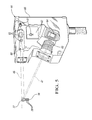
- FIG. 3 is a schematic perspective view of a threaded fastener and a plurality of angularly-spaced, triangulation-based, sensor heads at an imaging station;
- FIG. 4 is a top schematic block diagram view of a plurality of angularly-spaced sensor heads of at least one embodiment of the invention
- FIG. 5 is a schematic perspective view (partially broken away) of the various components of a sensor head of a preferred embodiment of the system
- FIG. 6 is a graph wherein a thread profile and some of its parameters are illustrated
- FIG. 7 is a schematic, perspective view, in cross section, of a continuous, seamless, 360 degree panoramic composite 3-D image or view formed by processing sets of 2-D profile signals;
- FIG. 8 is a schematic view wherein a framework in the illustrated figure is applied to a part such as a cartridge case once it has been located;
- FIG. 9 is a schematic view of a screen shot which describes a cartridge case or bullet to be inspected.
- FIG. 10 is a schematic view similar to the view of FIG. 8 wherein buffers are applied once the case regions has been identified.
- FIG. 11 is a block diagram flow chart illustrating a high-speed, triangulation-based, 3-D method of optically inspecting and sorting the inspected parts in accordance with at least one embodiment of the invention.
- At least one embodiment of the present invention provides a high-speed, triangulation-based, 3-D method and system for inspecting manufactured parts at an imaging station and sorting the inspected parts.
- the parts such as ammunition cases or threaded fasteners, have a length, a width, a part axis and an outer peripheral surface which extends 360° around the part.
- one embodiment of the high-speed, triangulation-based, 3-D method and system of the present invention optically inspects manufactured parts such as cartridge cases or fasteners or bolts as illustrated in FIGS. 1 and 2 .
- the inspected parts are then typically sorted based on the inspection.
- the system 10 is designed for the inspection of the outer peripheral surface of such cases or fasteners.
- the system 10 is also suitable for other small, mass-produced manufactured parts.
- the subsystems of the system 10 which may be used for part handling and delivery may vary widely from application to application depending on part size and shape, as well as what inspection is being conducted.
- the subsystems ultimately chosen for part handling and delivery have some bearing on the nature of the subsystem conducting the optical inspection.
- parts such as bolts 36 ( FIG. 2 ) are placed into a source of parts such as a feeder bowl (not shown) having a scalloped rim.
- the bowl is supported on an adjustable frame structure. Tooling around the rim takes advantage of the asymmetrical mass distribution of the bolts 36 to feed the bolts 36 onto a downwardly sloped vibratory feeder conveyor or loader 16 . Consequently, every bolt 36 which exits the bowl is received by the conveyor 16 and is oriented in the same direction as shown in FIG. 2 .
- One or more vibrators (not shown) controlled by a vibrator controller (not shown) vibrate the bowl and the conveyor 16 to help move the bolts 36 in single file to a loading station. At the loading station the longitudinal axes of the bolts 36 are substantially parallel.
- a part transfer subsystem, generally indicated at 18 , of the high-speed, triangulation-based 3-D system 10 is provided to transfer the bolts 36 from the loading station, to an unloading station, where the now unsupported bolts 36 fall under the force of gravity.
- the subsystem 18 includes a transfer mechanism in the form of metering wheel 22 which is, preferably, made of an optically transparent plastic material such as acrylic.
- the wheel 22 has openings formed about its outer peripheral surface which are adapted to receive and support the bolts 36 at the loading station and to transfer the supported bolts 36 so that the bolts 36 travel along a first path indicated by an arrow 25 which extends from the loading station to the unloading station at which each bolt 36 has a predetermined position and orientation.
- the bolts 36 are supported on the wheel 22 during wheel rotation by a stationary guide 26 .
- the wheel 22 is rotated by an electric motor 28 under the control of a motor controller 30 to rotate about its axis.
- the system 10 also includes a system controller 52 which controls and coordinates the inspection of the bolts 36 with the transfer of the bolts 36 to control movement of the bolts 36 and the inspection of the bolts 33 .
- the results of the processing by at least one processor such as a signal processor 50 are output to the system controller 52 which controls the system 10 based on the results of the optical inspection.
- Sensors 54 provide various timing or position signals to the controller 52 to help control the system 10 .
- one type of sensor may signal the controller 52 when the bolts 36 are located at or near the imaging station in the system 10 so that sensor heads, generally indicated at 44 in FIGS. 2-5 , can be controlled by the controller 52 to take “pictures” of the bolts 36 at the imaging station.
- the system 10 may also include a display and a user interface to permit two-way user interaction with the system 10 .
- the bolts 36 may be dropped onto a track 56 which may take the form of an AMPCO 18 oriented at a 35° angle. As the bolts 36 slide down and exit the track 56 , they pass through the imaging station to be inspected one at a time. Bolts 36 which pass the inspection may be actively accepted by a part diverter or flipper 32 located a few inches below the bottom end of the track 56 . The solenoid-actuated flipper 32 actively accepts those parts which have passed the above inspection into an acceptable part receive area 33 . The flipper 32 rests by default in its reject position so that parts will not be falsely accepted in the unlikely event of a hardware or software malfunction.
- a plurality of angularly-spaced, triangulation-based sensor heads 44 are supported and mounted within the imaging station.
- the sensor heads 44 simultaneously illuminate a plurality of exterior side surfaces of each bolt 36 with focused planes or lines 45 of radiation to obtain corresponding reflected lines 47 when the part 36 is in the imaging station as indicated by the sensors 54 ( FIG. 2 ).
- the exterior side surfaces are angularly spaced about an axis 39 of the part 36 .
- the sensor heads 44 simultaneously sense their corresponding reflected lines 47 to obtain corresponding 2-D profile signals.
- At least one processor processes the sets of 2-D profile signals to obtain a 360° panoramic composite 3-D view of the outer peripheral surface of the part 36 .
- the 3-D view may be continuous and seamless as shown in FIG. 7 by “stitching” the various views together.
- the system controller 55 provides control signals based on the signals from the sensors 54 .
- the control signals are utilized to control the sensor heads 44 which preferably have inputs which allow precise control over the position of 2-D profile signals samples.
- the bolts 36 may be undercut to have a radially extending surface wherein the focused lines 45 are angled with respect to the radially extending surface.
- the 3-D view may include at least a portion of the radially extending surface in this example.
- the at least one processor may process the sets of 2-D profile signals to identify a defective part as described in greater detail hereinbelow.
- the at least one processor may process the sets of 2-D profile signals to obtain a measurement of the part as also described in greater detail hereinbelow.
- Each of the sensor heads 44 may comprise a high-speed, 2D/3D laser scanner (LJ-V7000 series) available from Keyence Corporation of Japan.
- LJ-V7000 series high-speed, 2D/3D laser scanner
- Such a sensor head from Keyence generates a laser beam that has been expanded into a line and is reflected from the surface of the part.
- This reflected line of light is formed on a HSE3-CMOS sensor and by detecting changes in the position and shape of the reflection, it is possible to measure the position of various points along the surface of the part.
- Such a sensor head 44 typically includes ( FIG. 5 ) a cylindrical lens 60 , at least one and preferably two semiconductor laser diodes 61 , a GP64-Processor 62 , a 2D Ernostar lens 63 and a HSE3-CMOS Sensor 64 .
- the laser diodes 61 emit “blue” light beams which are polarized and combined by optical elements or components 65 to form the line of laser light 45 .
- the beams from the pair of blue laser diodes 61 are combined such that the transmitted beam is polarized in both X and Y axes.
- the captured images at the sensor 64 in both polarizations are used to generate a resulting 2-D profile signal wherein stray reflections are cancelled.
- the laser light source and receiver are independent of each other, greatly complicating on-site installation and adjustment.
- the laser light source and receiver are contained in a single body or enclosure 66 , making transmitter-to-receiver mounting adjustment unnecessary. This also ensures that the transmitter and receiver maintain this alignment regardless of machine use.
- the height of individual pixels and pixel pitch vary due to the relative positions of the laser light source and the receiver, requiring on-site linearization following installation.
- the output data is pre-linearized by the on-board controller (not shown) of the sensor head 44 without the need for additional post-processing.
- each such sensor head 44 is not a machine vision camera, but a traceable measurement device, traceability and calibration documentation is available out of the box. All such devices are factory calibrated to international traceability standards and compliance documentation is readily available.
- the sensor heads 44 and the at least one processor can extract serrations, knurls, twelve point aerospace or non-symmetric features of parts like D-head or T-head bolts etc.
- the operator may tell the system controller ( FIG. 2 ) via a display and user interface where the interesting parameters are located on the part axis (height of the part).
- the software tools extract and measure features from the images and resulting 2-D profile signals created by the sensed reflected lines of radiation.
- the 2-D profile signals may be pre-processed by the processor 62 and then processed by the at least one processor 50 under system control to obtain a 360 degree panoramic composite view or image which is used by the processor 50 to determine at least one of a dent, a split, a perforation, a crack, a scratch, a wrinkle, a buckle, a bulge, and a surface blemish located at the side surfaces of the part where the part is an ammunition case.
- the system 10 is an integrated system designed to fully inspect and measure parts from their sides without any need for part rotation at the imaging station.
- the system 10 can inspect parts which are supported such as a track which has a slit formed therein to allow a 360° unobstructed view of the part 36 .
- Each optical path is designed so that the displacement angle between the views is almost exactly 90° (or 120° if three sensor heads 44 are provided).
- This optical layout ensures complete coverage of the case's (or fastener's) lateral surfaces.
- the optical path is the same for all four viewpoints.
- imaging makes the system 10 relatively insensitive to part decentering and therefore suitable for measurement applications.
- the system 10 provides a solution for inspecting parts, such as cases or fasteners, whose features would be hidden when looked at from the top and for all those applications where a part must be inspected or measured from different sides without part rotation.
- FIG. 7 is a schematic, perspective view, in cross section, of a continuous, seamless, 360 degree panoramic composite 3-D image or view formed by processing a plurality of separate sets of 2-D profile signals. Each “curved” 3-D view may be “stitched” or joined together by a conventional image processing algorithm to form the 3-D view.
- FIG. 11 is a detailed block diagram flow chart describing a method of at least one embodiment of the present invention, generally indicated at 100 , as follows:
- block 114 is “no” reject part as being defective (block 118 ).
- This vision system 10 is especially designed for the inspection of relatively small manufactured parts such as threaded fasteners and small and medium caliber ammunition.
- the processing of images and/or signals of the cartridge cases to detect defective cases is generally described in issued U.S. Pat. No. 7,403,872 as described in the following Appendix with regard to a composite image.
- the detection of dents relies on the alteration of the angle of reflected light caused by a surface deformation on the inspected part. Light which is incident on a surface dent will reflect along a different axis than light which is incident on a non-deformed section of circumference.
- One option is to orient the light source so that light reflected off the part exterior is aimed directly into the sensor head aperture. Light which reflects off a dented region will not reflect bright background. Alternatively, the light source can be positioned with a shallower angle to the part. This will result in a low background illumination level with dents appearing as well deemed origin spots on the image.
- the vision system detects dents on parts with multiple tapered sections.
- a bright background is created in highly tapered regions (with dents appearing as dark spots) while a dim background is created in flatter regions (with dents appearing as bright spots).
- the software need not auto-locate the part and identify regions of interest using preset visual clues.
- Defect detection in each region of interest is typically conducted by first running several image processing algorithms and then analyzing the resultant pixel brightness values. Groups of pixels whose brightness values exceed a preset threshold are flagged as a “bright defect,” while groups of pixels whose brightness values lie below a preset threshold are flagged as a “dark defect.” Different image processing techniques and threshold values are often needed to inspect for bright and dark defects, even within the same part region.
- Previously locating the part in the composite image may be accomplished by running a series of linear edge detection algorithms. This algorithm uses variable threshold, smoothing and size settings to determine the boundary between a light and dark region along a defined line. These three variables are not generally available to the user, but are hard-coded into the software, as the only time they will generally need to change is in the event of large scale lighting adjustments.
- the software first uses the above edge detection algorithm to find the back (left) end of the part in the image.
- the software runs four more edge searches along the top and bottom edges of the part.
- the midpoints of the edge pairs are calculated and joined in order to find the centerline.
- the centerline search is then performed again, but rather than conducting the linear edge detections in the vertical direction, they are conducted perpendicular to the newly found centerline. This iteration reduces the small angle error associated with any potential misalignment of the part in the field of view.
- a framework of part regions is defined using a hard-coded model of the anticipated part shape.
- the regions defined by the framework include head, extractor groove, case, taper, and neck.
- Each of these regions can be varied in length and width through the user interface in order to adapt the software to varying case sizes. Note that although regions can be adjusted in size, they cannot have their bulk shape changed.
- a checkbox allows the taper and neck regions to be removed in order to inspect pistol cases (which do not have a taper).
- the size of the region framework as well as the state of the Taper/No-Taper checkbox is saved in the part profile.
- FIG. 8 shows the definition of the various regions on the part.
- This region definition is shown in screenshot of FIG. 9 . Note how the diameter of the groove has been set to be the same as the diameter of the case, resulting in a rectangular groove profile, rather than the trapezoid that is more frequently used.
- a buffer distance is applied to the inside edges of each region. These buffered regions define the area within which the defect searches will be conducted. By buffering the inspection regions, edge anomalies and non-ideal lighting frequently found near the boundaries are ignored.
- the size of the buffers can be independently adjusted for each region as part of the standard user interface and is saved in the part profile. This concept is demonstrated in FIG. 10 .
- the parameters associated with the algorithm can be modified from region to region. Additionally, the detection of dark and/or bright defects can be disabled for specific regions. This information is saved in the part profile.
- the detection of dark defects is a 6 step process.
- Logarithm Each, pixel brightness value (0-255) is replaced with the log of its brightness value. This serves to expand the brightness values of darker regions while compressing the values of brighter regions, thereby making it easier to find dark defects on a dim background.
- Sobel Magnitude Operator The Sobel Operator is the derivative of the image. Therefore, the Sobel Magnitude is shown below:
- the Sobel Magnitude Operator highlights pixels according to the difference between their brightness and the brightness of their neighbors. Since this operator is performed after the Logarithm filter applied in step 1, the resulting image will emphasize dark pockets on an otherwise dim background. After the Sobel Magnitude Operator is applied, the image will contain a number of bright ‘rings’ around the identified dark defects.
- Invert Original Image The original image captured by the camera is inverted so that bright pixels appear dark and dark pixels appear bright. This results in an image with dark defect areas appearing as bright spots.
- Multiplication the image obtained after step 2 is multiplied with the image obtained after step 3. Multiplication of two images like this is functionally equivalent to performing an AND operation on them. Only pixels which appear bright in the resultant image. In this case, the multiplication of these two images will result in the highlighting of the rings found in step two, but only if these rings surround a dark spot.
- Threshold All pixels with a brightness below a specified value are set to OFF while all pixels greater than or equal to the specified value are set to ON.
- the resultant image should consist of a pixels corresponding to potential defects. These bright blobs are superimposed on areas that originally contained dark defects.
- the detection of bright defects is a two-step process.
- Threshold A pixel brightness threshold filter may be applied to pick out all saturated pixels (greyscale255). A user-definable threshold may be provided so values lower than 255 can be detected.
- a count filter is a technique for filtering small pixel noise.
- a size parameter is set (2, 3, 4, etc) and a square box is constructed whose sides are this number of pixels in length. Therefore, if the size parameter is set to 3, the box will be 3 pixels by 3 pixels. This box is then centered on every pixel picked out by the threshold filter applied in step 1. The filter then counts the number of additional pixels contained within the box which have been flagged by the threshold filter and verifies that there is at least one other saturated pixel present. Any pixel which fails this test has its brightness set to 0. The effect of this filter operation is to blank out isolated noise pixels.
- the resultant binary image will consist of ON pixels corresponding to potential defects. Furthermore, any “speckling” type noise in the original image which would have results in an ON pixel will have been eliminated leaving only those pixels which are in close proximity to other pixels which are ON.
- the resultant processed images are binary. These two images are then OR'ed together. This results in a single image with both bright and dark defects.
- the software now counts the number of ON pixels in each detected defect. Finally, the part will be flagged as defective if either the quantity of defect pixels within a given connected region is above a user-defined threshold, or if the total quantity of defect pixels across the entire part is above a user-defined threshold.
- Thread signal processing is the process of estimating the following thread parameters.
- major diameter is estimated as twice the radius of the 3-D crest cylinder.
- the 3-D crest cylinder axis then depends on the precise crest/root locations.
- the crest/root locations then depend on the search intervals based on rough crest locations and pos/neg crossings, and on data from the original calibrated part data.
- the thread processing occurs between position limits called an inspection region.
- the user specifies the inspection region via a user interface ( FIG. 2 ) by manipulating the upper and lower stage position limits, overlaid on an image of the part.
- the estimation of thread parameters is specified to be an average estimate over all the data within which the inspection region.
- some of the intermediate data products are estimated outside of the inspection region in order to allow estimation of all thread parameters within the full region. For example, a wire position within the inspection region may require a thread crest outside the inspection region.
- the following requirements guide the user's placement of the inspection region on the image of the part.
- the first assumption is that the thread parameters be constant throughout the inspection region. This enables the software to average the estimates from different positions within the inspection region and not be concerned with partitioning or segmenting the data into different regions for special processing.
- a second assumption is that the inspection region contains at least 4-6 thread pitches. This amount of data is required to construct several of the intermediate data products with the required accuracy.
- a third assumption is that the thread be manufactured with a 60-degree flank angle. Thread processing implicitly utilizes this parameter in several places. One of the most direct usages is the conversion of lead deviation into functional diameter.
- a fourth assumption is that the thread has a cylindrical cross section.
- Non-cylindrical threads would require the 3-D peak cylinder to be suitably generalized. Incorrect fit to a non-cylindrical cross section would lead to incorrect lead deviation measures.
- a fifth assumption is that the thread has a single helix.
- Thread model describes herein below is a sampled representation of one thread profile, for exactly one pitch. Thread model starts at the midpoint of a rising thread flank and ends one pitch later.
- the thread model is matched to data within the inspection regions producing thresholded detections within the inspection region, that are called crossings.
- FIG. 6 illustrates selected concepts of a thread form.
- the thread model is a lateral sequence of points that represent a best estimate of the outline of one cycle of the thread form.
- a crest/root detector extracts rough crest and root positions between the matched adjacent pairs of positive and negative crossings.
- a pitch estimate is required for step set gage wire diameter.
- the estimate is required to be accurate enough to unambiguously select a unique gage wire from the set appropriate for the measurement.
- the current process utilizes a two-stage process.
- Crossing data is analyzed and averaged over all sensors to create a thread pitch estimate, the “crossing pitch.”
- the steps set wire gage diameter, wire position search intervals, measure flank lines and measure 3-point diameters noted herein below are completed in a first iteration. Then the wire positions are averaged over all sensors and positions to compute a pitch estimate.
- Gage wires are utilized in physical thread measurements of pitch diameter in the prior art. Two wires are placed in adjacent threads on one side of the part, and a single wire is placed on the other side of the part. A micrometer measures the distance between the reference line established by the two adjacent gage wires and the reference point established by the other gage wire. A tabulated correction formula converts the micrometer distance to an estimate of the pitch diameter.
- Gage wire sizes are thus selected prior to the thread measurement. To do this one estimates the thread pitch as previously described and then one selects the closest gage wire in a set to the pitch estimate.
- the gage wire set utilized is the one appropriate to the type of measurement; currently there is one set for the metric coarse thread sequence, and another for a similar English thread set.
- the gage wire sets are chosen at part template edit time by making a selection in a pull down list.
- wire positions in the inspection region have no gaps.
- a wire position search interval consist of two valid thread crests, one valid thread root between the two thread crests, and valid positive/negative crossings between the crest/root pairs.
- flank line data extraction region that covers 70% (a configurable parameter) of the height interval between left crest and central root. This data is extracted into a data set and fit to a line, becoming the left flank line.
- flank line valid is computed, based on the RMS distance between the left flank line and the data within the left flank line data extraction region. If the RMS distance between the flank line and the data points in the flank line data extraction interval is larger than 10 ⁇ m per point (a configurable parameter), then the flag is set to invalid.
- the wire positions are calculated, given the left and right flank lines and the wire size.
- the virtual wire is tangent to each flank line and the resulting position is calculated with a simple geometric formula.
- the position has a valid flag that is true when both flank lines are valid, and false otherwise.
- the 3-point technique is a method to measure the minor, major, and pitch diameters without explicitly utilizing 3-D information.
- the major diameter It is defined as the diameter of a cylinder that contains all the inspection region's thread crests.
- the top of a thread crest in calibrated sensor coordinates forms an elementary measurement.
- the elementary measurements are combined into triplets for further analysis.
- Two adjacent thread crest positions are combined with the thread crest position that is closest to the average position of crests.
- the two crests form a reference line. Then the distance from the reference line to the crest is computed. This is the 3 crest distance for that crest triplet.
- the 3-crest distances from all adjacent crest triplets are computed.
- the 3-crest distances are all added to a data vector.
- the 3-crest diameter measurement is either the average or the median of all the 3-crest distances within the 3-crest data vector.
- the 3-point minor diameter computes 3-point distances using precise root locations in the sensor data.
- the 3-point minor diameter is the average of the 3-point distance vector.
- the 3-point major diameter computes 3-crest distances using precise crest locations in the sensor data.
- the 3-point major diameter is the median of the 3-point distance vector.
- the 3-point pitch diameter computes 3-point distances using the wire positions computed in the sensor data.
- the 3-point wire pitch diameter is the median of the 3-point wire pitch diameter.
- the measured thread crest position data is analyzed to obtain a 3-D cylinder with least squares methods.
- the 3-D crest cylinder fit has several output parameters of interest.
- Measured wire positions can be combined with the 3-D location of the 3-D crest cylinder's central axis.
- An imaginary disk, perpendicular to the cylinder axis that goes through the measured wire position marks a position on the 3-D crest cylinder axis.
- a data set consisting of the projections of all sensor wire positions is constructed.
- the output intermediate data is a vector, sorted from minimum to maximum sensor stage position of the projected wire positions.
- Thread parameter estimation utilizes the intermediate data products and may also correct them based on a model of the measurement, prior to producing a final thread parameter estimate.
- Thread pitch is estimated from the wire center intermediate data. For each sensor data set the adjacent pairs of wire positions are used to calculate an adjacent wire pitch, one per adjacent wire positions. For all lasers, each wire pitch is added to a wire pitch vector.
- the wire pitch estimate is the median of the elements in the wire pitch vector.
- Thread major diameter is typically reported as the diameter of the 3-D crest cylinder.
- the major diameter is estimated from the 3-point major diameter data. This case is special because a previous condition (cylinder fit) has already failed. In practice, the cylinder fit most often failed when the threaded region was too short or the inspection extended beyond the end of the threaded region.
- the major diameter estimate is the value such that 20% of the 3-point data is higher and 80% of the 3-point data is lower.
- Major diameter is also corrected by a final end-to-end calibration of the total system.
- the reported major diameter is often two low, with bias ranging from ⁇ 20 ⁇ m to 0.
- Thread minor diameter is estimated with the 3-point minor diameter distance vector.
- the minor diameter value is the average of the elements in the distance vector.
- Pitch diameter estimation uses two sets of intermediate data products, the wire positions and the 3-D crest cylinder fit.
- the pitch diameter estimate calculation is presented in a step-by-step list below:
- the thread cross section is specified in thread design documents.
- the cross section is the thread shape if it were cut by a plane going through the thread's central axis.
- Pitch diameter is corrected by a final end-to-end calibration of the total system.
- the reported pitch diameter is often too high, with bias ranging from +5 ⁇ m to +35 ⁇ m.
- the lead deviation estimate uses the wire pitch and the locations of the wire positions as projected onto the 3-D cylinder fit axis.
- the wire position projections should result in a regular pattern along the 3-D cylinder fit axis.
- Lead deviation is the deviation of that pattern from the ideal, measured as a maximum distance of any projected wire position from the ideal pattern.
- Errors in measurement mean that the physical measurement of a perfect thread will have a positive lead deviation.
- This value observed in calibration with thread gages is taken to be a bias. This amount of bias is entered into the system calibration file and used to correct the measured lead deviation for this measurement bias.
- Functional diameter is currently defined in practice by the fit of a special fit gage over the thread.
- the special fit gage is essentially a nut that is split in two by a plane cut through the central axis of the nut. The two halves of the fit gage are held in a fixture that measures the distance between the two halves. There is one special fit gage for every thread type.
- Functional diameter is defined as the pitch diameter when the special fit gage is clamped tightly over a thread plug setting gage.
- the fit gage may expand slightly, due to a summation of effects involving the differences between the part and the thread plug setting gage used to setup the functional diameter measurement.
- the functional diameter measurement is then the thread plug setting gage's pitch diameter plus the additional separation between the two fit gage pieces.
- the functional diameter measurement method is an approximation of the fit gage method.
- the thread model is a learned sequence of points that represent a best estimate of the outline of one cycle of the thread form.
- the thread model is calculated when the inspection region is specified, at template edit time.
- the measure template routine uses a pattern match algorithm with a sine wave pattern to identify periodically in the inspection region data. This process determines an approximate thread pitch. The process also calculates a starting point in the data vector for the first beginning of the matched pattern, which is an approximation to the first midpoint of a right flank line.
- the measure template routine can then calculate an average thread model. Starting with the first sample point in the matched pattern, points that are 1, 2, 3, . . . , N pitches later in the inspection region are averaged to form the first point of the thread model. The process is repeated for all the rest of the points in the first matched pattern. The thread model is then stored in the template for later use.
Landscapes
- Physics & Mathematics (AREA)
- Health & Medical Sciences (AREA)
- Life Sciences & Earth Sciences (AREA)
- Chemical & Material Sciences (AREA)
- Analytical Chemistry (AREA)
- Biochemistry (AREA)
- General Health & Medical Sciences (AREA)
- General Physics & Mathematics (AREA)
- Immunology (AREA)
- Pathology (AREA)
- Engineering & Computer Science (AREA)
- Multimedia (AREA)
- Length Measuring Devices By Optical Means (AREA)
- Investigating Materials By The Use Of Optical Means Adapted For Particular Applications (AREA)
Priority Applications (6)
| Application Number | Priority Date | Filing Date | Title |
|---|---|---|---|
| US13/901,868 US9486840B2 (en) | 2013-05-24 | 2013-05-24 | High-speed, triangulation-based, 3-D method and system for inspecting manufactured parts and sorting the inspected parts |
| PCT/US2014/016663 WO2014189566A1 (fr) | 2013-05-24 | 2014-02-17 | Procédé et système 3d à grande vitesse utilisant une triangulation pour inspecter des pièces fabriquées et trier les pièces inspectées |
| US14/221,410 US8993914B2 (en) | 2012-12-14 | 2014-03-21 | High-speed, high-resolution, triangulation-based, 3-D method and system for inspecting manufactured parts and sorting the inspected parts |
| US14/449,361 US9228957B2 (en) | 2013-05-24 | 2014-08-01 | High speed method and system for inspecting a stream of parts |
| US14/748,319 US9539619B2 (en) | 2013-05-24 | 2015-06-24 | High speed method and system for inspecting a stream of parts at a pair of inspection stations |
| US15/669,079 US10207297B2 (en) | 2013-05-24 | 2017-08-04 | Method and system for inspecting a manufactured part at an inspection station |
Applications Claiming Priority (1)
| Application Number | Priority Date | Filing Date | Title |
|---|---|---|---|
| US13/901,868 US9486840B2 (en) | 2013-05-24 | 2013-05-24 | High-speed, triangulation-based, 3-D method and system for inspecting manufactured parts and sorting the inspected parts |
Related Child Applications (1)
| Application Number | Title | Priority Date | Filing Date |
|---|---|---|---|
| US14/221,410 Continuation-In-Part US8993914B2 (en) | 2012-12-14 | 2014-03-21 | High-speed, high-resolution, triangulation-based, 3-D method and system for inspecting manufactured parts and sorting the inspected parts |
Publications (2)
| Publication Number | Publication Date |
|---|---|
| US20140346094A1 US20140346094A1 (en) | 2014-11-27 |
| US9486840B2 true US9486840B2 (en) | 2016-11-08 |
Family
ID=51933931
Family Applications (1)
| Application Number | Title | Priority Date | Filing Date |
|---|---|---|---|
| US13/901,868 Active 2034-04-04 US9486840B2 (en) | 2012-12-14 | 2013-05-24 | High-speed, triangulation-based, 3-D method and system for inspecting manufactured parts and sorting the inspected parts |
Country Status (2)
| Country | Link |
|---|---|
| US (1) | US9486840B2 (fr) |
| WO (1) | WO2014189566A1 (fr) |
Cited By (7)
| Publication number | Priority date | Publication date | Assignee | Title |
|---|---|---|---|---|
| US20170052024A1 (en) * | 2015-08-21 | 2017-02-23 | Adcole Corporation | Optical profiler and methods of use thereof |
| US10118201B2 (en) * | 2015-08-03 | 2018-11-06 | Linear Group Services, LLC | Inspection and sorting machine |
| WO2021092696A1 (fr) * | 2019-11-13 | 2021-05-20 | VISIONx INC. | Procédés et systèmes associés pour déterminer la conformité d'une partie ayant un profil irrégulier avec un dessin de référence |
| US11045842B2 (en) | 2019-05-16 | 2021-06-29 | General Inspection, Llc | Method and system for inspecting unidentified mixed parts at an inspection station having a measurement axis to identify the parts |
| US11162906B2 (en) | 2019-05-16 | 2021-11-02 | General Inspection, Llc | High-speed method and system for inspecting and sorting a stream of unidentified mixed parts |
| US11543364B2 (en) | 2019-05-16 | 2023-01-03 | General Inspection, Llc | Computer-implemented method of automatically generating inspection templates of a plurality of known good fasteners |
| US11975364B2 (en) * | 2020-12-02 | 2024-05-07 | Keylex Corporation | Component transfer device |
Families Citing this family (6)
| Publication number | Priority date | Publication date | Assignee | Title |
|---|---|---|---|---|
| US11176286B2 (en) | 2015-09-09 | 2021-11-16 | Xerox Corporation | System and method for internal structural defect analysis using three-dimensional sensor data |
| DE102016200324A1 (de) * | 2016-01-14 | 2017-07-20 | MTU Aero Engines AG | Verfahren zum Ermitteln einer Konzentration wenigstens eines Werkstoffs in einem Pulver für ein additives Herstellverfahren |
| CN107377415B (zh) * | 2017-07-10 | 2023-07-28 | 原秀科技(苏州)有限公司 | 工件批量检测设备 |
| US11741758B2 (en) | 2020-10-27 | 2023-08-29 | General Inspection, Llc | Inspection system for manufactured components |
| TWI843410B (zh) * | 2023-01-18 | 2024-05-21 | 銓益盛機械有限公司 | 用於螺絲搓牙機之物件檢測裝置 |
| CN117434084A (zh) * | 2023-12-06 | 2024-01-23 | 四川万圣通实业有限公司 | 一种钢管的数字化检测装置及检测方法 |
Citations (81)
| Publication number | Priority date | Publication date | Assignee | Title |
|---|---|---|---|---|
| US2645343A (en) | 1949-04-27 | 1953-07-14 | Kelling Nut Co | Photoelectric inspecting and sorting apparatus |
| US3770969A (en) | 1972-03-09 | 1973-11-06 | Owens Illinois Inc | Inspecting the bottom wall of hollow open-ended containers |
| US3924953A (en) | 1974-12-18 | 1975-12-09 | Us Navy | Helix pitch monitor |
| US4239969A (en) | 1978-11-16 | 1980-12-16 | North American Philips Corporation | Article inspection apparatus with protective chamber having article-loading facility |
| US4315688A (en) | 1979-08-08 | 1982-02-16 | Diffracto Ltd. | Electro-optical sensor systems for thread and hole inspection |
| US4547674A (en) | 1982-10-12 | 1985-10-15 | Diffracto Ltd. | Optical triangulation gear inspection |
| US4598998A (en) | 1982-02-25 | 1986-07-08 | Sumitomo Kinzoku Kogyo Kabushiki Kaisha | Screw surface flaw inspection method and an apparatus therefor |
| US4644394A (en) | 1985-12-31 | 1987-02-17 | Dale Reeves | Apparatus for inspecting an externally threaded surface of an object |
| US4721388A (en) | 1984-10-05 | 1988-01-26 | Hitachi, Ltd. | Method of measuring shape of object in non-contacting manner |
| US4831251A (en) | 1988-04-18 | 1989-05-16 | Mectron Engineering Company, Inc. | Right and left-hand screw thread optical discriminator |
| US4852983A (en) | 1987-09-21 | 1989-08-01 | Spectra-Physics, Inc. | Distance simulator |
| US4906098A (en) | 1988-05-09 | 1990-03-06 | Glass Technology Development Corporation | Optical profile measuring apparatus |
| US4923066A (en) | 1987-10-08 | 1990-05-08 | Elor Optronics Ltd. | Small arms ammunition inspection system |
| US4969746A (en) | 1988-09-02 | 1990-11-13 | R. J. Reynolds Tobacco Company | Component inspection apparatus and method |
| US4970401A (en) | 1988-01-22 | 1990-11-13 | Yaacov Sadeh | Non-contact triangulation probe system |
| US4983043A (en) | 1987-04-17 | 1991-01-08 | Industrial Technology Institute | High accuracy structured light profiler |
| US5012117A (en) | 1988-09-15 | 1991-04-30 | Alfred Teves Gmbh | Process and apparatus for the automatic non-contact surface inspection of cylindrical parts |
| US5024529A (en) | 1988-01-29 | 1991-06-18 | Synthetic Vision Systems, Inc. | Method and system for high-speed, high-resolution, 3-D imaging of an object at a vision station |
| US5098031A (en) | 1989-12-05 | 1992-03-24 | Shimano Corporation | Spinning reel with eccentric element for moving bail arm lever |
| US5164995A (en) | 1989-11-27 | 1992-11-17 | General Motors Corporation | Signature analysis apparatus |
| US5168458A (en) | 1990-03-16 | 1992-12-01 | Research Engineering & Manufacturing, Inc. | Method and apparatus for gaging the degree of lobulation of bodies such as threaded fasteners |
| US5170306A (en) | 1990-03-16 | 1992-12-08 | Research Engineering & Manufacturing, Inc. | Method and apparatus for gaging the geometry of point threads and other special threads |
| US5291272A (en) | 1991-09-27 | 1994-03-01 | Criterion Resources, Inc. | Method and apparatus for measuring dimensional variables of threaded pipe |
| US5383021A (en) | 1993-04-19 | 1995-01-17 | Mectron Engineering Company | Optical part inspection system |
| US5431289A (en) | 1994-02-15 | 1995-07-11 | Simco/Ramic Corporation | Product conveyor |
| US5521707A (en) | 1991-08-21 | 1996-05-28 | Apeiron, Inc. | Laser scanning method and apparatus for rapid precision measurement of thread form |
| US5531316A (en) | 1995-02-21 | 1996-07-02 | Bearings, Inc. | Conveyor belt and method of making same |
| US5546189A (en) | 1994-05-19 | 1996-08-13 | View Engineering, Inc. | Triangulation-based 3D imaging and processing method and system |
| US5608530A (en) | 1994-08-08 | 1997-03-04 | General Inspection, Inc. | Inspection device for measuring a geometric dimension of a part |
| US5617209A (en) | 1995-04-27 | 1997-04-01 | View Engineering, Inc. | Method and system for triangulation-based, 3-D imaging utilizing an angled scaning beam of radiant energy |
| US5646724A (en) | 1995-08-18 | 1997-07-08 | Candid Logic, Inc. | Threaded parts inspection device |
| US5847382A (en) | 1996-10-22 | 1998-12-08 | Jay Koch | Bone detector |
| US6046462A (en) | 1997-12-16 | 2000-04-04 | Eastman Kodak Company | Method and apparatus for determining orientation of parts resting on a flat surface |
| US6055329A (en) | 1994-06-09 | 2000-04-25 | Sherikon, Inc. | High speed opto-electronic gage and method for gaging |
| US6098031A (en) * | 1998-03-05 | 2000-08-01 | Gsi Lumonics, Inc. | Versatile method and system for high speed, 3D imaging of microscopic targets |
| US6252661B1 (en) | 1999-08-02 | 2001-06-26 | James L. Hanna | Optical sub-pixel parts inspection system |
| US6285034B1 (en) | 1998-11-04 | 2001-09-04 | James L. Hanna | Inspection system for flanged bolts |
| US20010021026A1 (en) | 1998-06-10 | 2001-09-13 | Liu Kuo-Ching | Method and system for imaging an object with a plurality of optical beams |
| US6289600B1 (en) | 1999-11-02 | 2001-09-18 | United States Pipe & Foundry Company | Non-contact measuring device |
| US6313948B1 (en) | 1999-08-02 | 2001-11-06 | James I. Hanna | Optical beam shaper |
| WO2005022076A2 (fr) | 2003-08-23 | 2005-03-10 | General Inspection, Llc | Appareil d'inspection de pieces |
| US20050174567A1 (en) | 2004-02-09 | 2005-08-11 | Mectron Engineering Company | Crack detection system |
| US6959108B1 (en) | 2001-12-06 | 2005-10-25 | Interactive Design, Inc. | Image based defect detection system |
| US7123765B2 (en) | 2002-07-31 | 2006-10-17 | Kimberly-Clark Worldwide, Inc. | Apparatus and method for inspecting articles |
| US20060236792A1 (en) | 2005-04-22 | 2006-10-26 | Mectron Engineering Company | Workpiece inspection system |
| US7134544B1 (en) | 2005-07-28 | 2006-11-14 | Fki Logistex, Inc. | Conveyor belt system with take-up device |
| US20070223009A1 (en) | 2006-03-22 | 2007-09-27 | Benteler Automobil Technik Gmbh | Apparatus and method for measuring structural parts |
| US7312607B2 (en) | 2004-07-20 | 2007-12-25 | General Inspection Llc | Eddy current part inspection system |
| US7363817B2 (en) | 2001-11-28 | 2008-04-29 | Battelle Memorial Institute | System and technique for detecting the presence of foreign material |
| US7403872B1 (en) | 2007-04-13 | 2008-07-22 | Gii Acquisition, Llc | Method and system for inspecting manufactured parts and sorting the inspected parts |
| US20090103107A1 (en) | 2007-10-23 | 2009-04-23 | Gii Acquisition, Llc Dba General Inspection, Llc | Method And System For Inspecting Parts Utilizing Triangulation |
| US20090103112A1 (en) | 2007-10-23 | 2009-04-23 | Gii Acquisition, Llc Dba General Inspection, Llc | Non-Contact Method And System For Inspecting Parts |
| US20090107896A1 (en) | 2007-10-30 | 2009-04-30 | Logical Systems Incorporated | Air separator conveyor and vision system |
| WO2009130062A1 (fr) | 2008-04-24 | 2009-10-29 | Claudio Sedazzari | Procédé et dispositif pour la visualisation optique d’objets |
| US7633046B2 (en) | 2007-10-23 | 2009-12-15 | Gii Acquisition Llc | Method for estimating thread parameters of a part |
| US7633634B2 (en) | 2007-10-23 | 2009-12-15 | Gii Acquisition, Llc | Optical modules and method of precisely assembling same |
| US7633635B2 (en) | 2006-08-07 | 2009-12-15 | GII Acquisitions, LLC | Method and system for automatically identifying non-labeled, manufactured parts |
| US7684054B2 (en) | 2006-08-25 | 2010-03-23 | Gii Acquisition, Llc | Profile inspection system for threaded and axial components |
| US20100084245A1 (en) | 2007-12-03 | 2010-04-08 | Thyssenkrupp Elevator (Es/Pbb) Ltd. | Conveyor system for the transport of passengers/goods |
| US7738121B2 (en) | 2007-10-23 | 2010-06-15 | Gii Acquisition, Llc | Method and inspection head apparatus for optically measuring geometric dimensions of a part |
| US7738088B2 (en) | 2007-10-23 | 2010-06-15 | Gii Acquisition, Llc | Optical method and system for generating calibration data for use in calibrating a part inspection system |
| US7755754B2 (en) | 2007-10-23 | 2010-07-13 | Gii Acquisition, Llc | Calibration device for use in an optical part measuring system |
| US20100201806A1 (en) | 2007-10-23 | 2010-08-12 | Gii Acquisition, Llc Dba General Inspection, Llc | Method and system for automatically inspecting parts and for automatically generating calibration data for use in inspecting parts |
| US7777900B2 (en) | 2007-10-23 | 2010-08-17 | Gii Acquisition, Llc | Method and system for optically inspecting parts |
| US7796278B2 (en) | 2008-09-19 | 2010-09-14 | Gii Acquisition, Llc | Method for precisely measuring position of a part to be inspected at a part inspection station |
| US20100245850A1 (en) | 2009-03-27 | 2010-09-30 | Gii Acquisition, Llc Dba General Inspection, Llc | System For Indirectly Measuring A Geometric Dimension Related To An Opening In An Apertured Exterior Surface of A Part Based On Direct Measurements Of The Part When Fixtured At A Measurement Station |
| US20110005899A1 (en) | 2008-03-16 | 2011-01-13 | Janusz Grzelak | Method and conveyor belt system having at least one conveyor belt for transporting flat transport goods |
| US8054460B2 (en) | 2008-05-12 | 2011-11-08 | GM Global Technology Operations LLC | Methodology for evaluating the start and profile of a thread with a vision-based system |
| US20120105429A1 (en) | 2010-10-29 | 2012-05-03 | Gii Acquisition, Llc Dba General Inspection, Llc | Method and system for high-speed, high-resolution 3-d imaging of manufactured parts of various sizes |
| US8179434B2 (en) | 2008-05-09 | 2012-05-15 | Mettler-Toledo, LLC | System and method for imaging of curved surfaces |
| US8228493B2 (en) | 2007-06-19 | 2012-07-24 | Qualicaps Co., Ltd. | Carrying device and appearance inspection device for test objects |
| US20120285751A1 (en) | 2007-09-13 | 2012-11-15 | Raf Technology, Inc. | In-line conveyor scale with integrated closed-loop servo sensor |
| US20120293623A1 (en) | 2011-05-17 | 2012-11-22 | Gii Acquisition, Llc Dba General Inspection, Llc | Method and system for inspecting small manufactured objects at a plurality of inspection stations and sorting the inspected objects |
| US20120293789A1 (en) | 2011-05-17 | 2012-11-22 | Gii Acquisition, Llc Dba General Inspection, Llc | Method and system for optically inspecting parts |
| US20120303157A1 (en) | 2009-11-25 | 2012-11-29 | Chung Jing-Yau | Rejection of defective vegetable with scattering and refracting light |
| US8390826B2 (en) | 2011-04-20 | 2013-03-05 | Gii Acquisition, Llc | Method and system for optically inspecting parts |
| US20130235371A1 (en) | 2012-03-07 | 2013-09-12 | Gii Acquisition, Llc Dba General Inspection, Llc | High-speed, 3-d method and system for optically inspecting parts |
| US8615123B2 (en) | 2010-09-15 | 2013-12-24 | Identicoin, Inc. | Coin identification method and apparatus |
| US20140043610A1 (en) | 2012-08-07 | 2014-02-13 | Carl Zeiss Industrielle Messtechnik Gmbh | Apparatus for inspecting a measurement object with triangulation sensor |
| US20140063509A1 (en) | 2012-03-07 | 2014-03-06 | Gii Acquisition, Llc Dba General Inspection, Llc | High-speed method and system for optically measuring a geometric dimension of manufactured parts |
| US20140168661A1 (en) | 2012-12-14 | 2014-06-19 | Gii Acquisition, Llc Dba General Inspection, Llc | High-speed, 3-d method and system for optically measuring a geometric dimension of manufactured parts |
-
2013
- 2013-05-24 US US13/901,868 patent/US9486840B2/en active Active
-
2014
- 2014-02-17 WO PCT/US2014/016663 patent/WO2014189566A1/fr active Application Filing
Patent Citations (84)
| Publication number | Priority date | Publication date | Assignee | Title |
|---|---|---|---|---|
| US2645343A (en) | 1949-04-27 | 1953-07-14 | Kelling Nut Co | Photoelectric inspecting and sorting apparatus |
| US3770969A (en) | 1972-03-09 | 1973-11-06 | Owens Illinois Inc | Inspecting the bottom wall of hollow open-ended containers |
| US3924953A (en) | 1974-12-18 | 1975-12-09 | Us Navy | Helix pitch monitor |
| US4239969A (en) | 1978-11-16 | 1980-12-16 | North American Philips Corporation | Article inspection apparatus with protective chamber having article-loading facility |
| US4315688A (en) | 1979-08-08 | 1982-02-16 | Diffracto Ltd. | Electro-optical sensor systems for thread and hole inspection |
| US4598998A (en) | 1982-02-25 | 1986-07-08 | Sumitomo Kinzoku Kogyo Kabushiki Kaisha | Screw surface flaw inspection method and an apparatus therefor |
| US4547674A (en) | 1982-10-12 | 1985-10-15 | Diffracto Ltd. | Optical triangulation gear inspection |
| US4721388A (en) | 1984-10-05 | 1988-01-26 | Hitachi, Ltd. | Method of measuring shape of object in non-contacting manner |
| US4644394A (en) | 1985-12-31 | 1987-02-17 | Dale Reeves | Apparatus for inspecting an externally threaded surface of an object |
| US4983043A (en) | 1987-04-17 | 1991-01-08 | Industrial Technology Institute | High accuracy structured light profiler |
| US4852983A (en) | 1987-09-21 | 1989-08-01 | Spectra-Physics, Inc. | Distance simulator |
| US4923066A (en) | 1987-10-08 | 1990-05-08 | Elor Optronics Ltd. | Small arms ammunition inspection system |
| US4970401A (en) | 1988-01-22 | 1990-11-13 | Yaacov Sadeh | Non-contact triangulation probe system |
| US5024529A (en) | 1988-01-29 | 1991-06-18 | Synthetic Vision Systems, Inc. | Method and system for high-speed, high-resolution, 3-D imaging of an object at a vision station |
| US4831251A (en) | 1988-04-18 | 1989-05-16 | Mectron Engineering Company, Inc. | Right and left-hand screw thread optical discriminator |
| US4906098A (en) | 1988-05-09 | 1990-03-06 | Glass Technology Development Corporation | Optical profile measuring apparatus |
| US4969746A (en) | 1988-09-02 | 1990-11-13 | R. J. Reynolds Tobacco Company | Component inspection apparatus and method |
| US5012117A (en) | 1988-09-15 | 1991-04-30 | Alfred Teves Gmbh | Process and apparatus for the automatic non-contact surface inspection of cylindrical parts |
| US5164995A (en) | 1989-11-27 | 1992-11-17 | General Motors Corporation | Signature analysis apparatus |
| US5098031A (en) | 1989-12-05 | 1992-03-24 | Shimano Corporation | Spinning reel with eccentric element for moving bail arm lever |
| US5168458A (en) | 1990-03-16 | 1992-12-01 | Research Engineering & Manufacturing, Inc. | Method and apparatus for gaging the degree of lobulation of bodies such as threaded fasteners |
| US5170306A (en) | 1990-03-16 | 1992-12-08 | Research Engineering & Manufacturing, Inc. | Method and apparatus for gaging the geometry of point threads and other special threads |
| US5521707A (en) | 1991-08-21 | 1996-05-28 | Apeiron, Inc. | Laser scanning method and apparatus for rapid precision measurement of thread form |
| US5291272A (en) | 1991-09-27 | 1994-03-01 | Criterion Resources, Inc. | Method and apparatus for measuring dimensional variables of threaded pipe |
| US5383021A (en) | 1993-04-19 | 1995-01-17 | Mectron Engineering Company | Optical part inspection system |
| US5568263A (en) | 1993-04-19 | 1996-10-22 | Mectron Engineering Company | Non-contact inspection system |
| US5431289A (en) | 1994-02-15 | 1995-07-11 | Simco/Ramic Corporation | Product conveyor |
| US5546189A (en) | 1994-05-19 | 1996-08-13 | View Engineering, Inc. | Triangulation-based 3D imaging and processing method and system |
| US6055329A (en) | 1994-06-09 | 2000-04-25 | Sherikon, Inc. | High speed opto-electronic gage and method for gaging |
| US5608530A (en) | 1994-08-08 | 1997-03-04 | General Inspection, Inc. | Inspection device for measuring a geometric dimension of a part |
| US5531316A (en) | 1995-02-21 | 1996-07-02 | Bearings, Inc. | Conveyor belt and method of making same |
| US5617209A (en) | 1995-04-27 | 1997-04-01 | View Engineering, Inc. | Method and system for triangulation-based, 3-D imaging utilizing an angled scaning beam of radiant energy |
| US5815275A (en) | 1995-04-27 | 1998-09-29 | General Scanning, Inc. | Method and system for triangulation-based, 3-D imaging utilizing an angled scanning beam of radiant energy |
| US5646724A (en) | 1995-08-18 | 1997-07-08 | Candid Logic, Inc. | Threaded parts inspection device |
| US5847382A (en) | 1996-10-22 | 1998-12-08 | Jay Koch | Bone detector |
| US6046462A (en) | 1997-12-16 | 2000-04-04 | Eastman Kodak Company | Method and apparatus for determining orientation of parts resting on a flat surface |
| US6098031A (en) * | 1998-03-05 | 2000-08-01 | Gsi Lumonics, Inc. | Versatile method and system for high speed, 3D imaging of microscopic targets |
| US20010021026A1 (en) | 1998-06-10 | 2001-09-13 | Liu Kuo-Ching | Method and system for imaging an object with a plurality of optical beams |
| US6285034B1 (en) | 1998-11-04 | 2001-09-04 | James L. Hanna | Inspection system for flanged bolts |
| US6252661B1 (en) | 1999-08-02 | 2001-06-26 | James L. Hanna | Optical sub-pixel parts inspection system |
| US6313948B1 (en) | 1999-08-02 | 2001-11-06 | James I. Hanna | Optical beam shaper |
| US6289600B1 (en) | 1999-11-02 | 2001-09-18 | United States Pipe & Foundry Company | Non-contact measuring device |
| US7363817B2 (en) | 2001-11-28 | 2008-04-29 | Battelle Memorial Institute | System and technique for detecting the presence of foreign material |
| US6959108B1 (en) | 2001-12-06 | 2005-10-25 | Interactive Design, Inc. | Image based defect detection system |
| US7123765B2 (en) | 2002-07-31 | 2006-10-17 | Kimberly-Clark Worldwide, Inc. | Apparatus and method for inspecting articles |
| WO2005022076A2 (fr) | 2003-08-23 | 2005-03-10 | General Inspection, Llc | Appareil d'inspection de pieces |
| US20050174567A1 (en) | 2004-02-09 | 2005-08-11 | Mectron Engineering Company | Crack detection system |
| US7312607B2 (en) | 2004-07-20 | 2007-12-25 | General Inspection Llc | Eddy current part inspection system |
| US20060236792A1 (en) | 2005-04-22 | 2006-10-26 | Mectron Engineering Company | Workpiece inspection system |
| US7134544B1 (en) | 2005-07-28 | 2006-11-14 | Fki Logistex, Inc. | Conveyor belt system with take-up device |
| US20070223009A1 (en) | 2006-03-22 | 2007-09-27 | Benteler Automobil Technik Gmbh | Apparatus and method for measuring structural parts |
| US7633635B2 (en) | 2006-08-07 | 2009-12-15 | GII Acquisitions, LLC | Method and system for automatically identifying non-labeled, manufactured parts |
| US7684054B2 (en) | 2006-08-25 | 2010-03-23 | Gii Acquisition, Llc | Profile inspection system for threaded and axial components |
| US7403872B1 (en) | 2007-04-13 | 2008-07-22 | Gii Acquisition, Llc | Method and system for inspecting manufactured parts and sorting the inspected parts |
| US8228493B2 (en) | 2007-06-19 | 2012-07-24 | Qualicaps Co., Ltd. | Carrying device and appearance inspection device for test objects |
| US20120285751A1 (en) | 2007-09-13 | 2012-11-15 | Raf Technology, Inc. | In-line conveyor scale with integrated closed-loop servo sensor |
| US20100201806A1 (en) | 2007-10-23 | 2010-08-12 | Gii Acquisition, Llc Dba General Inspection, Llc | Method and system for automatically inspecting parts and for automatically generating calibration data for use in inspecting parts |
| US20090103107A1 (en) | 2007-10-23 | 2009-04-23 | Gii Acquisition, Llc Dba General Inspection, Llc | Method And System For Inspecting Parts Utilizing Triangulation |
| US7633046B2 (en) | 2007-10-23 | 2009-12-15 | Gii Acquisition Llc | Method for estimating thread parameters of a part |
| US7633634B2 (en) | 2007-10-23 | 2009-12-15 | Gii Acquisition, Llc | Optical modules and method of precisely assembling same |
| US20090103112A1 (en) | 2007-10-23 | 2009-04-23 | Gii Acquisition, Llc Dba General Inspection, Llc | Non-Contact Method And System For Inspecting Parts |
| US7738121B2 (en) | 2007-10-23 | 2010-06-15 | Gii Acquisition, Llc | Method and inspection head apparatus for optically measuring geometric dimensions of a part |
| US7738088B2 (en) | 2007-10-23 | 2010-06-15 | Gii Acquisition, Llc | Optical method and system for generating calibration data for use in calibrating a part inspection system |
| US7755754B2 (en) | 2007-10-23 | 2010-07-13 | Gii Acquisition, Llc | Calibration device for use in an optical part measuring system |
| US7777900B2 (en) | 2007-10-23 | 2010-08-17 | Gii Acquisition, Llc | Method and system for optically inspecting parts |
| US20090107896A1 (en) | 2007-10-30 | 2009-04-30 | Logical Systems Incorporated | Air separator conveyor and vision system |
| US20100084245A1 (en) | 2007-12-03 | 2010-04-08 | Thyssenkrupp Elevator (Es/Pbb) Ltd. | Conveyor system for the transport of passengers/goods |
| US20110005899A1 (en) | 2008-03-16 | 2011-01-13 | Janusz Grzelak | Method and conveyor belt system having at least one conveyor belt for transporting flat transport goods |
| WO2009130062A1 (fr) | 2008-04-24 | 2009-10-29 | Claudio Sedazzari | Procédé et dispositif pour la visualisation optique d’objets |
| US8179434B2 (en) | 2008-05-09 | 2012-05-15 | Mettler-Toledo, LLC | System and method for imaging of curved surfaces |
| US8054460B2 (en) | 2008-05-12 | 2011-11-08 | GM Global Technology Operations LLC | Methodology for evaluating the start and profile of a thread with a vision-based system |
| US7796278B2 (en) | 2008-09-19 | 2010-09-14 | Gii Acquisition, Llc | Method for precisely measuring position of a part to be inspected at a part inspection station |
| US20100245850A1 (en) | 2009-03-27 | 2010-09-30 | Gii Acquisition, Llc Dba General Inspection, Llc | System For Indirectly Measuring A Geometric Dimension Related To An Opening In An Apertured Exterior Surface of A Part Based On Direct Measurements Of The Part When Fixtured At A Measurement Station |
| US20120303157A1 (en) | 2009-11-25 | 2012-11-29 | Chung Jing-Yau | Rejection of defective vegetable with scattering and refracting light |
| US8615123B2 (en) | 2010-09-15 | 2013-12-24 | Identicoin, Inc. | Coin identification method and apparatus |
| US20120105429A1 (en) | 2010-10-29 | 2012-05-03 | Gii Acquisition, Llc Dba General Inspection, Llc | Method and system for high-speed, high-resolution 3-d imaging of manufactured parts of various sizes |
| US8390826B2 (en) | 2011-04-20 | 2013-03-05 | Gii Acquisition, Llc | Method and system for optically inspecting parts |
| US20120293789A1 (en) | 2011-05-17 | 2012-11-22 | Gii Acquisition, Llc Dba General Inspection, Llc | Method and system for optically inspecting parts |
| US8570504B2 (en) | 2011-05-17 | 2013-10-29 | Gii Acquisition, Llc | Method and system for optically inspecting parts |
| US20120293623A1 (en) | 2011-05-17 | 2012-11-22 | Gii Acquisition, Llc Dba General Inspection, Llc | Method and system for inspecting small manufactured objects at a plurality of inspection stations and sorting the inspected objects |
| US20130235371A1 (en) | 2012-03-07 | 2013-09-12 | Gii Acquisition, Llc Dba General Inspection, Llc | High-speed, 3-d method and system for optically inspecting parts |
| US20140063509A1 (en) | 2012-03-07 | 2014-03-06 | Gii Acquisition, Llc Dba General Inspection, Llc | High-speed method and system for optically measuring a geometric dimension of manufactured parts |
| US20140043610A1 (en) | 2012-08-07 | 2014-02-13 | Carl Zeiss Industrielle Messtechnik Gmbh | Apparatus for inspecting a measurement object with triangulation sensor |
| US20140168661A1 (en) | 2012-12-14 | 2014-06-19 | Gii Acquisition, Llc Dba General Inspection, Llc | High-speed, 3-d method and system for optically measuring a geometric dimension of manufactured parts |
Non-Patent Citations (11)
| Title |
|---|
| Brosed, Francisco Javier, et al.; 3D Geometrical Inspection of Complex Geometry Parts Using a Novel Laser Triangulation Sensor and a Robot; Sensors 2011, 11, 9-110; doi:10.3390/s110100090; published Dec. 23, 2010. |
| International Preliminary Report on Patentability; related PCT application serial No. PCT/US2014/016662; date of issuance of report Nov. 24, 2015. |
| International Preliminary Report on Patentability; related PCT application serial No. PCT/US2014/016663; date of issuance of report Nov. 24, 2015. |
| International Search Report and Written Opinion; International application No. PCT/US15/34349; date of mailing Sep. 15, 2015. |
| International Search Report and Written Opinion; International application No. PCT/US2014/016663; date of mailing May 28, 2014. |
| International Search Report and Written Opinion; International application No. PCT/US2015/016307; date of mailing Jun. 3, 2015. |
| International Search Report and Written; International application No. PCT/US14/16662; date of mailing Dec. 8, 2014. |
| Notice of Allowance and Fee(s) Due; corresponding U.S. Appl. No. 14/449,361; date mailed Sep. 8, 2015. |
| Notice of Allowance and Fee(s) Due; U.S. Appl. No. 14/221,410; date of mailing Dec. 5, 2014. |
| Office Action; related U.S. Appl. No. 14/449,361; notification date May 15, 2015. |
| Yogeswaran, Arjun; 3D Surface Analysis for the Automated Detection of Deformations on Automotive Panels; Ottawa-Carleton Institute for Electrical and Computer Engineering School for Information Technology and Engineering, University of Ottawa; Apr. 2011. |
Cited By (8)
| Publication number | Priority date | Publication date | Assignee | Title |
|---|---|---|---|---|
| US10118201B2 (en) * | 2015-08-03 | 2018-11-06 | Linear Group Services, LLC | Inspection and sorting machine |
| US20170052024A1 (en) * | 2015-08-21 | 2017-02-23 | Adcole Corporation | Optical profiler and methods of use thereof |
| US11045842B2 (en) | 2019-05-16 | 2021-06-29 | General Inspection, Llc | Method and system for inspecting unidentified mixed parts at an inspection station having a measurement axis to identify the parts |
| US11162906B2 (en) | 2019-05-16 | 2021-11-02 | General Inspection, Llc | High-speed method and system for inspecting and sorting a stream of unidentified mixed parts |
| US11543364B2 (en) | 2019-05-16 | 2023-01-03 | General Inspection, Llc | Computer-implemented method of automatically generating inspection templates of a plurality of known good fasteners |
| US11623250B2 (en) | 2019-05-16 | 2023-04-11 | General Inspection, Llc | Method and system for sorting inspected parts |
| WO2021092696A1 (fr) * | 2019-11-13 | 2021-05-20 | VISIONx INC. | Procédés et systèmes associés pour déterminer la conformité d'une partie ayant un profil irrégulier avec un dessin de référence |
| US11975364B2 (en) * | 2020-12-02 | 2024-05-07 | Keylex Corporation | Component transfer device |
Also Published As
| Publication number | Publication date |
|---|---|
| WO2014189566A1 (fr) | 2014-11-27 |
| US20140346094A1 (en) | 2014-11-27 |
Similar Documents
| Publication | Publication Date | Title |
|---|---|---|
| US9486840B2 (en) | High-speed, triangulation-based, 3-D method and system for inspecting manufactured parts and sorting the inspected parts | |
| US9575013B2 (en) | Non-contact method and system for inspecting a manufactured part at an inspection station having a measurement axis | |
| US9370799B2 (en) | Method and system for optically inspecting a manufactured part at a single inspection station having a measurement axis | |
| US9019489B2 (en) | Method and system for optically inspecting parts | |
| US9047657B2 (en) | Method and system for optically inspecting outer peripheral surfaces of parts | |
| US9697596B2 (en) | Method and system for optically inspecting parts | |
| US10094785B2 (en) | Method and system for optically inspecting headed manufactured parts | |
| US7403872B1 (en) | Method and system for inspecting manufactured parts and sorting the inspected parts | |
| US8896844B2 (en) | High-speed, 3-D method and system for optically measuring a geometric dimension of manufactured parts | |
| US8993914B2 (en) | High-speed, high-resolution, triangulation-based, 3-D method and system for inspecting manufactured parts and sorting the inspected parts | |
| US8004694B2 (en) | System for indirectly measuring a geometric dimension related to an opening in an apertured exterior surface of a part based on direct measurements of the part when fixtured at a measurement station | |
| US10088431B2 (en) | Method and system for optically inspecting headed manufactured parts | |
| JP5676387B2 (ja) | 外観検査方法及びその装置 | |
| US20140063509A1 (en) | High-speed method and system for optically measuring a geometric dimension of manufactured parts | |
| US10207297B2 (en) | Method and system for inspecting a manufactured part at an inspection station | |
| CN108805870A (zh) | 一种带针座的接插件的检测方法 | |
| US20140347438A1 (en) | Triangulation-based, 3-d method and system for imaging the outer peripheral surface of a part | |
| JP6040215B2 (ja) | 検査方法 | |
| WO2015142457A1 (fr) | Procédé et système en 3d, basés sur la triangulation, haute résolution et haute vitesse pour l'examen de pièces fabriquées et le tri des pièces examinées | |
| CN109701890A (zh) | 磁瓦表面缺陷检测与分拣方法 | |
| WO2014178936A2 (fr) | Procédé et système d'inspection optique de surfaces périphériques extérieures de pièces | |
| Laurowski et al. | Use-appropriate design of automated optical inspection systems for rotationally symmetric parts |
Legal Events
| Date | Code | Title | Description |
|---|---|---|---|
| AS | Assignment |
Owner name: GII ACQUISITION, LLC DBA GENERAL INSPECTION, LLC, Free format text: ASSIGNMENT OF ASSIGNORS INTEREST;ASSIGNOR:NYGAARD, MICHAEL G.;REEL/FRAME:030492/0559 Effective date: 20130521 |
|
| STCF | Information on status: patent grant |
Free format text: PATENTED CASE |
|
| MAFP | Maintenance fee payment |
Free format text: PAYMENT OF MAINTENANCE FEE, 4TH YR, SMALL ENTITY (ORIGINAL EVENT CODE: M2551); ENTITY STATUS OF PATENT OWNER: SMALL ENTITY Year of fee payment: 4 |
|
| MAFP | Maintenance fee payment |
Free format text: PAYMENT OF MAINTENANCE FEE, 8TH YR, SMALL ENTITY (ORIGINAL EVENT CODE: M2552); ENTITY STATUS OF PATENT OWNER: SMALL ENTITY Year of fee payment: 8 |