US948571A - Universal controlling-valve. - Google Patents
Universal controlling-valve. Download PDFInfo
- Publication number
- US948571A US948571A US1909489802A US948571A US 948571 A US948571 A US 948571A US 1909489802 A US1909489802 A US 1909489802A US 948571 A US948571 A US 948571A
- Authority
- US
- United States
- Prior art keywords
- valve
- base
- dome
- brake
- universal controlling
- Prior art date
- Legal status (The legal status is an assumption and is not a legal conclusion. Google has not performed a legal analysis and makes no representation as to the accuracy of the status listed.)
- Expired - Lifetime
Links
- 230000001276 controlling effect Effects 0.000 description 7
- 241000049552 Pteris tremula Species 0.000 description 2
- 238000010276 construction Methods 0.000 description 2
- 229920000136 polysorbate Polymers 0.000 description 1
- 238000009877 rendering Methods 0.000 description 1
- 230000008439 repair process Effects 0.000 description 1
Images
Classifications
-
- B—PERFORMING OPERATIONS; TRANSPORTING
- B62—LAND VEHICLES FOR TRAVELLING OTHERWISE THAN ON RAILS
- B62D—MOTOR VEHICLES; TRAILERS
- B62D5/00—Power-assisted or power-driven steering
- B62D5/06—Power-assisted or power-driven steering fluid, i.e. using a pressurised fluid for most or all the force required for steering a vehicle
- B62D5/09—Power-assisted or power-driven steering fluid, i.e. using a pressurised fluid for most or all the force required for steering a vehicle characterised by means for actuating valves
- B62D5/093—Telemotor driven by steering wheel movement
- B62D5/097—Telemotor driven by steering wheel movement gerotor type
-
- Y—GENERAL TAGGING OF NEW TECHNOLOGICAL DEVELOPMENTS; GENERAL TAGGING OF CROSS-SECTIONAL TECHNOLOGIES SPANNING OVER SEVERAL SECTIONS OF THE IPC; TECHNICAL SUBJECTS COVERED BY FORMER USPC CROSS-REFERENCE ART COLLECTIONS [XRACs] AND DIGESTS
- Y10—TECHNICAL SUBJECTS COVERED BY FORMER USPC
- Y10T—TECHNICAL SUBJECTS COVERED BY FORMER US CLASSIFICATION
- Y10T137/00—Fluid handling
- Y10T137/8593—Systems
- Y10T137/86493—Multi-way valve unit
- Y10T137/86574—Supply and exhaust
- Y10T137/86638—Rotary valve
-
- Y—GENERAL TAGGING OF NEW TECHNOLOGICAL DEVELOPMENTS; GENERAL TAGGING OF CROSS-SECTIONAL TECHNOLOGIES SPANNING OVER SEVERAL SECTIONS OF THE IPC; TECHNICAL SUBJECTS COVERED BY FORMER USPC CROSS-REFERENCE ART COLLECTIONS [XRACs] AND DIGESTS
- Y10—TECHNICAL SUBJECTS COVERED BY FORMER USPC
- Y10T—TECHNICAL SUBJECTS COVERED BY FORMER US CLASSIFICATION
- Y10T137/00—Fluid handling
- Y10T137/8593—Systems
- Y10T137/86493—Multi-way valve unit
- Y10T137/86574—Supply and exhaust
- Y10T137/86638—Rotary valve
- Y10T137/86646—Plug type
- Y10T137/86662—Axial and radial flow
Definitions
- Our invention relates to valves for con trolling the operations of mechanism which are actuated by compressed air, steam or vapors under pressure, and it consists in the combinations, constructions and arrangements hereinafter described and claimed.
- An object of our invention is to provide a device, in which, by the simple manipulation of an'operating handle, the control of the various pipes and cylinders in an air brake system is effected.
- a further object of our invention is to provide a novel form of controlling valve in which all bolts and gaskets are eliminated and which is of simple construction owing to the small number of parts.
- a further object of our invention is to rovide a controlling valve which can be aken apart readily to clean,,oil or make repairs without necessitating any break in the pipe joint or their connections.
- Afurther object of our invention is to provide a controlling valve with relatively large ports, thereby reducing the liability of the ports becoming clogged, thus rendering the mechanism unfit for use until it is cleaned.
- FIG. 2 is a lan view of the base portion of the controlling valve.
- Fig. 2 is a section along the line 22 of Fig. 2.
- Fig. 2" is a side view of the base portion.
- Fig. 3 is a plan view of the operating handle and the dome.
- Fig. 4 1s a plan view of the rotary valve.
- Fig. 4 is an inverted section through the rotary valve on the line 4"-4 of Fig. a.
- Fig. 4 is a section through the rotary valve on the line 49-4 of Fig. 4.
- Fig. 5 is a pepspective view of the rotary valve
- 6 is a perspective view of the base portion.
- a base denoted in general by A, of the general form shown in Figs. 1, 2, 2 and 2
- the base portion is provided with a central vertical opening a and the three ports a, a and a as clearly shown in Figs. 2 and 2. All three of the ports a, a and a communicate with threaded openings in the bottom of the base into which pipes (not shown) may be screwed.
- the upper part a of the base A constitutes a valve seat.
- a lug a Immediately below the valve seat is an enlarged threaded portion a, while on one side there is a lug a, provided with a threaded opening a for the attachment of a supporting member, see Fig. 2
- the rotary valve proper B is shown in Figs. 4, 4 4 and 5. It consists of a cylindrical block having the vertical openings b and b therethrou h of the shape shown in Figs. 4 and 5. 5n one side'of the block there is a vertical channel 6 which extends part way into the block and communicates with a transverse channel 6 see Fig. 4 On the opposite side are two projecting lugs b and b Referring now particularly to Fig. 1 it will be seen that there is a dome C which rests upon the base A and incloses the valve B. The inner cylindrical face of the dome keeps the valve B centered on the base. The dome is secured to the base portion by means of a nut D. The latter may be a spanner: nut or it may be a six, eight, ten or twelve sided nut. The dome C is kept from rotating by means of one or more dowel pins 0.
- valve stem L Arranged to roject through an opening in the top of the dome is a valve stem L having a tapered tongue 6, adapted tofit be tween the projectinglugs Z) and b of the valve.
- the purpose of making the tongue e of a tapered or wedge shaped form is to msure proper assembling at. all times.
- the up per art of the valve stem E has a reduced portion a adapted to receive the end of an operating handle F, which is secured to the stem by means of the key f and the nut Gr on the threaded end 0 of the stem E.
- the latch is rounded on its end so that while it will hold the handle steady in any one position, it may be easily shifted to another position by pressure applied to the handle.
- the ports a, a and 0 are connecte respectively to a feed valve set at 45 pounds pressure which is supplied by the main reservoir, to a triple valve exhaust and to the brake cylinder.
- the center port or hole a is used as the exhaust and leads to the atmosphere as shown.
- the small hole a which extends through the valve to the outer atmosphere is used as a warning port.
- the position W see Fig. 3, is the release, is the running position, Y lap and Z service positions, respectively'
- the release position the brake cylinders on the engine are in direct communication with the atmosphere and the feed valve pressure is in communication with the one-sixteenth inch warning port, making a hissing sound so that the engineer will not allow the handle to remain in this position after the air has esca ed from the brake cylinders. If he should 0 so and make an application of the automatic brakes, he would have no engine brake.
- the triple valve exhaust port When the handle is shifted to the running position the triple valve exhaust port is in direct communication with the atmosphere and" in this way gives the regular automatic brake on the engine. In lap position both the triple valve exhaustand the brake cylinder ports are blanked, thus allowing the engine brakes to be held and the train brakes released.
- the automatic brake as at present to release the engine brake without releasing the tender or out of registration with the side channels in said base, a dome supported upon said base having an inner cylindrical face for keeping said valve centered on said base, means carried by said base for centering said dome, a nut for securing said dome to said base, a detachable valve stem having a centrally disposed tongue arranged to engage the central portion of said valve and a handle for operating said valve stem.
Landscapes
- Engineering & Computer Science (AREA)
- Chemical & Material Sciences (AREA)
- Combustion & Propulsion (AREA)
- Transportation (AREA)
- Mechanical Engineering (AREA)
- Mechanically-Actuated Valves (AREA)
Description
W. 0. ARP, F. F. HILDRETH 6; F. N. RUMBLEY. UNIVERSAL CONTROLLING VALVE.
APPLICATION FILED APR.14, 1909. 9 5} a Patented Feb. 8, 1910.
Z SHEETS-SHEET 1.
ATTOR/VE w W. 0. ARP, F. F. HILDRETH & P. N. RUMBLEY. UNIVERSAL CONTROLLING VALVE.
APPLIOATION FILED APR.14, 1909. 94 M" Patented Feb.8,1910.
2 SHEETS-SHEET 2.
ATTORNEYS ITE SATES ti WILL'IAM c. ARP, FRED r. HILDRETH, AND FREDERICK NEw'ronnoMnLEY, or
TERRE HAUTE, INDIANA.
UNIVERSAL oonrnomme vnnvn.
Specification ofILettei-s Patent. Patented Feb. 8, 1911)..
Application filed April 14, 1909. Serial No. 489,802.
To all whom it may concern:
Be it known that we, WILLIAM, C. Aer, Fnno F.QHILDRETH, and FREDERICK N. RUM- BLEY, citizens of the United States, and residents of Terre Haute, in the county of Vigo and State of Indiana, have made certain new and useful Improvements in Universal Controlling-Valves, of which the following as a specification.
Our invention relates to valves for con trolling the operations of mechanism which are actuated by compressed air, steam or vapors under pressure, and it consists in the combinations, constructions and arrangements hereinafter described and claimed.
An object of our invention is to provide a device, in which, by the simple manipulation of an'operating handle, the control of the various pipes and cylinders in an air brake system is effected.
A further object of our invention is to provide a novel form of controlling valve in which all bolts and gaskets are eliminated and which is of simple construction owing to the small number of parts.
A further object of our invention is to rovide a controlling valve which can be aken apart readily to clean,,oil or make repairs without necessitating any break in the pipe joint or their connections.
Afurther object of our invention is to provide a controlling valve with relatively large ports, thereby reducing the liability of the ports becoming clogged, thus rendering the mechanism unfit for use until it is cleaned. Other objects and advantages will appear in the following specification and the novel features of the device will be particularly pointed out in the appended claim.
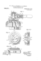
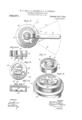
Our invention is illustrated in the accompanying drawings, in which similar reference characters indicate like parts in the several views, and in which Figure l is a central vertical section through the device. Fig. 2 is a lan view of the base portion of the controlling valve. Fig. 2 is a section along the line 22 of Fig. 2. Fig. 2" is a side view of the base portion. Fig. 3 is a plan view of the operating handle and the dome. Fig. 4 1s a plan view of the rotary valve. Fig. 4 is an inverted section through the rotary valve on the line 4"-4 of Fig. a. Fig. 4 is a section through the rotary valve on the line 49-4 of Fig. 4. Fig. 5 is a pepspective view of the rotary valve, and 6 is a perspective view of the base portion.
In carrying out our invention we provide a base, denoted in general by A, of the general form shown in Figs. 1, 2, 2 and 2 The base portion is provided with a central vertical opening a and the three ports a, a and a as clearly shown in Figs. 2 and 2. All three of the ports a, a and a communicate with threaded openings in the bottom of the base into which pipes (not shown) may be screwed. The upper part a of the base A constitutes a valve seat. Immediately below the valve seat is an enlarged threaded portion a, while on one side there is a lug a, provided with a threaded opening a for the attachment of a supporting member, see Fig. 2
The rotary valve proper B, is shown in Figs. 4, 4 4 and 5. It consists of a cylindrical block having the vertical openings b and b therethrou h of the shape shown in Figs. 4 and 5. 5n one side'of the block there is a vertical channel 6 which extends part way into the block and communicates with a transverse channel 6 see Fig. 4 On the opposite side are two projecting lugs b and b Referring now particularly to Fig. 1 it will be seen that there is a dome C which rests upon the base A and incloses the valve B. The inner cylindrical face of the dome keeps the valve B centered on the base. The dome is secured to the base portion by means of a nut D. The latter may be a spanner: nut or it may be a six, eight, ten or twelve sided nut. The dome C is kept from rotating by means of one or more dowel pins 0.
Arranged to roject through an opening in the top of the dome is a valve stem L having a tapered tongue 6, adapted tofit be tween the projectinglugs Z) and b of the valve. The purpose of making the tongue e of a tapered or wedge shaped form is to msure proper assembling at. all times. The up per art of the valve stem E has a reduced portion a adapted to receive the end of an operating handle F, which is secured to the stem by means of the key f and the nut Gr on the threaded end 0 of the stem E. The
engage in notches formed between the lugs c on the dome C. The latch is rounded on its end so that while it will hold the handle steady in any one position, it may be easily shifted to another position by pressure applied to the handle.
From the foregoing description of the various parts of the device the operation thereof may be readily understood.
In )IfiCtlCe the ports a, a and 0, are connecte respectively to a feed valve set at 45 pounds pressure which is supplied by the main reservoir, to a triple valve exhaust and to the brake cylinder. The center port or hole a is used as the exhaust and leads to the atmosphere as shown. The small hole a which extends through the valve to the outer atmosphere is used as a warning port.
There are four positions of the handle. The position W, see Fig. 3, is the release, is the running position, Y lap and Z service positions, respectively' In the release position the brake cylinders on the engine are in direct communication with the atmosphere and the feed valve pressure is in communication with the one-sixteenth inch warning port, making a hissing sound so that the engineer will not allow the handle to remain in this position after the air has esca ed from the brake cylinders. If he should 0 so and make an application of the automatic brakes, he would have no engine brake.
When the handle is shifted to the running position the triple valve exhaust port is in direct communication with the atmosphere and" in this way gives the regular automatic brake on the engine. In lap position both the triple valve exhaustand the brake cylinder ports are blanked, thus allowing the engine brakes to be held and the train brakes released.
In service position the brake cylinders ar put in slight communication with the feed valve, thus allowing the engine and tender brakes to set and in full service position they are putin direct communication, thus allowing them to set quickly. In piping this Mam i straight air to the tender all that is necessary is that the brake cylinder pipe be carried back to the brake cylinder pipe on the tender through a double check valve. With this arrangement the engine brakes can be released without releasing the tender brakes for an automatic application.
With our lnvention it is possible to use the automatic brake as at present to release the engine brake without releasing the tender or out of registration with the side channels in said base, a dome supported upon said base having an inner cylindrical face for keeping said valve centered on said base, means carried by said base for centering said dome, a nut for securing said dome to said base, a detachable valve stem having a centrally disposed tongue arranged to engage the central portion of said valve and a handle for operating said valve stem.
WILLIAM C. Alt-P. FRED I". llll'DRETH. FREDERICK NEWTON RUMBIIEY- Witnesses to signature of William Arp and Fred F. Hildreth:
JOHN W. PARKS, WILBER C. PITMAN. Witnesses to signature of Frederick N. Rumbley:
CHAS. HUBBARD,
M. W. MAoRAn.
Priority Applications (1)
| Application Number | Priority Date | Filing Date | Title |
|---|---|---|---|
| US1909489802 US948571A (en) | 1909-04-14 | 1909-04-14 | Universal controlling-valve. |
Applications Claiming Priority (1)
| Application Number | Priority Date | Filing Date | Title |
|---|---|---|---|
| US1909489802 US948571A (en) | 1909-04-14 | 1909-04-14 | Universal controlling-valve. |
Publications (1)
| Publication Number | Publication Date |
|---|---|
| US948571A true US948571A (en) | 1910-02-08 |
Family
ID=3016987
Family Applications (1)
| Application Number | Title | Priority Date | Filing Date |
|---|---|---|---|
| US1909489802 Expired - Lifetime US948571A (en) | 1909-04-14 | 1909-04-14 | Universal controlling-valve. |
Country Status (1)
| Country | Link |
|---|---|
| US (1) | US948571A (en) |
Cited By (2)
| Publication number | Priority date | Publication date | Assignee | Title |
|---|---|---|---|---|
| US20180163898A1 (en) * | 2016-12-14 | 2018-06-14 | Fisher Controls International Llc | Single-piece valve closure members having integral flow paths formed via additive manufacturing |
| US11085546B2 (en) | 2018-04-10 | 2021-08-10 | Fisher Controls International Llc | Purge apparatus for use with fluid valves |
-
1909
- 1909-04-14 US US1909489802 patent/US948571A/en not_active Expired - Lifetime
Cited By (3)
| Publication number | Priority date | Publication date | Assignee | Title |
|---|---|---|---|---|
| US20180163898A1 (en) * | 2016-12-14 | 2018-06-14 | Fisher Controls International Llc | Single-piece valve closure members having integral flow paths formed via additive manufacturing |
| US10107417B2 (en) * | 2016-12-14 | 2018-10-23 | Fisher Controls International Llc | Single-piece valve closure members having integral flow paths formed via additive manufacturing |
| US11085546B2 (en) | 2018-04-10 | 2021-08-10 | Fisher Controls International Llc | Purge apparatus for use with fluid valves |
Similar Documents
| Publication | Publication Date | Title |
|---|---|---|
| US1023104A (en) | Alarm-valve. | |
| US1270722A (en) | Valve for train-pipes. | |
| US1200668A (en) | Valve. | |
| US715113A (en) | Balanced valve. | |
| US1524225A (en) | Locomotive turret | |
| US600829A (en) | Arthur d | |
| US734978A (en) | Valve mechanism. | |
| US810863A (en) | Coupling-section for train air-pipes. | |
| US246467A (en) | Three-way cock | |
| US341345A (en) | Throttle-valve | |
| US603043A (en) | Blow-off cock | |
| US695016A (en) | Valve. | |
| US543022A (en) | Air-brake-valve apparatus | |
| US535548A (en) | Air-brake valve | |
| US627103A (en) | Theodore h | |
| US930135A (en) | Valve. | |
| US784506A (en) | Air-brake system. | |
| US587272A (en) | Oiling device | |
| US1044049A (en) | Steam-actuating device for friction-driven drums. | |
| US481943A (en) | Di stri butin g-valve | |
| US647192A (en) | Renewable-seat valve. | |
| US731867A (en) | Angle-cock for air-brake systems. | |
| US1935285A (en) | Locomotive cylinder cock | |
| US1141161A (en) | Valve mechanism. | |
| US265880A (en) | Three-way cock for steam-brakes |