US9485219B1 - VPN for containers and virtual machines in local area networks - Google Patents
VPN for containers and virtual machines in local area networks Download PDFInfo
- Publication number
- US9485219B1 US9485219B1 US14/710,876 US201514710876A US9485219B1 US 9485219 B1 US9485219 B1 US 9485219B1 US 201514710876 A US201514710876 A US 201514710876A US 9485219 B1 US9485219 B1 US 9485219B1
- Authority
- US
- United States
- Prior art keywords
- ves
- vpn
- hardware
- data packet
- node
- Prior art date
- Legal status (The legal status is an assumption and is not a legal conclusion. Google has not performed a legal analysis and makes no representation as to the accuracy of the status listed.)
- Active
Links
- 238000000034 method Methods 0.000 claims abstract description 14
- 238000004590 computer program Methods 0.000 abstract description 4
- 230000015654 memory Effects 0.000 description 9
- 230000003287 optical effect Effects 0.000 description 7
- 230000006855 networking Effects 0.000 description 3
- 238000012545 processing Methods 0.000 description 3
- 238000005516 engineering process Methods 0.000 description 2
- 230000005055 memory storage Effects 0.000 description 2
- 230000002093 peripheral effect Effects 0.000 description 2
- 230000008569 process Effects 0.000 description 2
- 230000006978 adaptation Effects 0.000 description 1
- 238000002955 isolation Methods 0.000 description 1
- 238000012986 modification Methods 0.000 description 1
- 230000004048 modification Effects 0.000 description 1
- 230000008520 organization Effects 0.000 description 1
- 238000012546 transfer Methods 0.000 description 1
- 230000005641 tunneling Effects 0.000 description 1
Images


Classifications
-
- H—ELECTRICITY
- H04—ELECTRIC COMMUNICATION TECHNIQUE
- H04L—TRANSMISSION OF DIGITAL INFORMATION, e.g. TELEGRAPHIC COMMUNICATION
- H04L63/00—Network architectures or network communication protocols for network security
- H04L63/02—Network architectures or network communication protocols for network security for separating internal from external traffic, e.g. firewalls
- H04L63/0272—Virtual private networks
-
- H—ELECTRICITY
- H04—ELECTRIC COMMUNICATION TECHNIQUE
- H04L—TRANSMISSION OF DIGITAL INFORMATION, e.g. TELEGRAPHIC COMMUNICATION
- H04L12/00—Data switching networks
- H04L12/02—Details
- H04L12/16—Arrangements for providing special services to substations
- H04L12/18—Arrangements for providing special services to substations for broadcast or conference, e.g. multicast
- H04L12/1886—Arrangements for providing special services to substations for broadcast or conference, e.g. multicast with traffic restrictions for efficiency improvement, e.g. involving subnets or subdomains
-
- G—PHYSICS
- G06—COMPUTING; CALCULATING OR COUNTING
- G06F—ELECTRIC DIGITAL DATA PROCESSING
- G06F9/00—Arrangements for program control, e.g. control units
- G06F9/06—Arrangements for program control, e.g. control units using stored programs, i.e. using an internal store of processing equipment to receive or retain programs
- G06F9/44—Arrangements for executing specific programs
- G06F9/455—Emulation; Interpretation; Software simulation, e.g. virtualisation or emulation of application or operating system execution engines
- G06F9/45533—Hypervisors; Virtual machine monitors
- G06F9/45558—Hypervisor-specific management and integration aspects
-
- H—ELECTRICITY
- H04—ELECTRIC COMMUNICATION TECHNIQUE
- H04L—TRANSMISSION OF DIGITAL INFORMATION, e.g. TELEGRAPHIC COMMUNICATION
- H04L12/00—Data switching networks
- H04L12/28—Data switching networks characterised by path configuration, e.g. LAN [Local Area Networks] or WAN [Wide Area Networks]
- H04L12/46—Interconnection of networks
- H04L12/4641—Virtual LANs, VLANs, e.g. virtual private networks [VPN]
-
- H04L65/4076—
-
- H—ELECTRICITY
- H04—ELECTRIC COMMUNICATION TECHNIQUE
- H04L—TRANSMISSION OF DIGITAL INFORMATION, e.g. TELEGRAPHIC COMMUNICATION
- H04L65/00—Network arrangements, protocols or services for supporting real-time applications in data packet communication
- H04L65/60—Network streaming of media packets
- H04L65/61—Network streaming of media packets for supporting one-way streaming services, e.g. Internet radio
- H04L65/611—Network streaming of media packets for supporting one-way streaming services, e.g. Internet radio for multicast or broadcast
-
- H04L67/2823—
-
- H—ELECTRICITY
- H04—ELECTRIC COMMUNICATION TECHNIQUE
- H04L—TRANSMISSION OF DIGITAL INFORMATION, e.g. TELEGRAPHIC COMMUNICATION
- H04L67/00—Network arrangements or protocols for supporting network services or applications
- H04L67/2866—Architectures; Arrangements
- H04L67/288—Distributed intermediate devices, i.e. intermediate devices for interaction with other intermediate devices on the same level
-
- H—ELECTRICITY
- H04—ELECTRIC COMMUNICATION TECHNIQUE
- H04L—TRANSMISSION OF DIGITAL INFORMATION, e.g. TELEGRAPHIC COMMUNICATION
- H04L67/00—Network arrangements or protocols for supporting network services or applications
- H04L67/50—Network services
- H04L67/56—Provisioning of proxy services
- H04L67/565—Conversion or adaptation of application format or content
-
- G—PHYSICS
- G06—COMPUTING; CALCULATING OR COUNTING
- G06F—ELECTRIC DIGITAL DATA PROCESSING
- G06F9/00—Arrangements for program control, e.g. control units
- G06F9/06—Arrangements for program control, e.g. control units using stored programs, i.e. using an internal store of processing equipment to receive or retain programs
- G06F9/44—Arrangements for executing specific programs
- G06F9/455—Emulation; Interpretation; Software simulation, e.g. virtualisation or emulation of application or operating system execution engines
- G06F9/45533—Hypervisors; Virtual machine monitors
- G06F9/45558—Hypervisor-specific management and integration aspects
- G06F2009/45587—Isolation or security of virtual machine instances
-
- G—PHYSICS
- G06—COMPUTING; CALCULATING OR COUNTING
- G06F—ELECTRIC DIGITAL DATA PROCESSING
- G06F9/00—Arrangements for program control, e.g. control units
- G06F9/06—Arrangements for program control, e.g. control units using stored programs, i.e. using an internal store of processing equipment to receive or retain programs
- G06F9/44—Arrangements for executing specific programs
- G06F9/455—Emulation; Interpretation; Software simulation, e.g. virtualisation or emulation of application or operating system execution engines
- G06F9/45533—Hypervisors; Virtual machine monitors
- G06F9/45558—Hypervisor-specific management and integration aspects
- G06F2009/45595—Network integration; Enabling network access in virtual machine instances
-
- H—ELECTRICITY
- H04—ELECTRIC COMMUNICATION TECHNIQUE
- H04L—TRANSMISSION OF DIGITAL INFORMATION, e.g. TELEGRAPHIC COMMUNICATION
- H04L63/00—Network architectures or network communication protocols for network security
- H04L63/02—Network architectures or network communication protocols for network security for separating internal from external traffic, e.g. firewalls
- H04L63/0281—Proxies
Definitions
- the present invention is related to Virtual Private Networks (VPNs) and, in particular, to a method and system for an effective VPN creation of Virtual Environments (VMs and containers) in local area networks.
- VPNs Virtual Private Networks
- VMs and containers Virtual Environments
- a virtual private network extends a private network across a public network, such as the Internet.
- the VPN enables a computer to send and receive data across shared or public networks as if it were directly connected to the private network, while benefiting from the functionality, security and management policies of the private network.
- the VPN is created by establishing a virtual point-to-point connection through the use of dedicated connections, virtual tunneling protocols, or traffic encryptions.
- the VPN connection across the Internet is similar to a wide area network (WAN) link between sites. From a user's perspective, the extended network resources are accessed in the same way as resources available within the private network.
- the VPNs allow employees to securely access their company's intranet while traveling outside the office.
- VPNs securely connect geographically separated offices of an organization, creating one cohesive network.
- the VPN technology is also used by Internet users to connect to proxy servers for the purpose of protecting personal identity and location.
- a modern trend of virtualization presents some challenges with regard to creating a VPN.
- the virtualization technology provides for several Virtual Environments (VEs)-Virtual Machines (VMs) and/or Containers (such as from PARALLELS) implemented on each of the hardware node of a network.
- VEs Virtual Environments
- VMs Virtual Machines
- Containers such as from PARALLELS
- VEs Virtual Environments
- VMs Virtual Machines
- Containers such as from PARALLELS
- the connection to corresponding VM or Container should be set up directly and adding new Containers to the VPN can be established through complicated procedures.
- the broadcasting of VPN packets may be used instead, but it is not secure when packets are routed on the hardware level and such an insecure form of implementation may be rejected by users and system administrators.
- the present invention is related to Virtual Private Networks (VPNs) and, in particular, to a method and system for a VPN creation for VEs (VMs and containers) that substantially overcomes the disadvantages of the related art.
- VPNs Virtual Private Networks
- VEs VEs and containers
- a method, system and computer program product for creating a VPN of VEs i.e., containers and VMs
- a number of network hardware nodes have containers and VMs running on them.
- the containers and VMs are logically aggregated into VPNs assembled across the hardware nodes.
- Each hardware node has a hardware network adapter and programmable switch configured to route packets from a hardware adapter to containers and VMs and vice versa only inside a particular VPN.
- the switch or router can determine which VPN the outgoing packet belongs to by checking from which (virtual) port the packet has arrived and processes the packet correspondingly.
- the switch replaces multicast identifier with a broadcast identifier and routes packet to VPN subscribers only. This defines limits on the distribution of the packets, since multi-cast packets may be received by subscribers only.
- broadcast packet is not distributed to all VEs of the hardware node on which the VEs run, but only to the VPN subscribers.
- the switch replaces the broadcast destination identifier with the multicast identifier corresponding to the group ID/Number the sending VM/CT belongs to.
- a broadcast protocol (e.g., ARP protocol) indicates from where broadcast packets appear from.
- ARP protocol e.g., ARP protocol
- a VPN identifier is broadcasted to all VEs of the hardware node, and then, only the VE nodes that have successfully requested the packet or packets can get the broadcast packets. If the multi-cast packet contains the MAC address of the destination VE, the VE requesting VPN packet with the certain MAC address receives the packet.
- FIG. 1 illustrates a VPN architecture for VEs, in accordance with the exemplary embodiment
- FIG. 2 illustrates a schematic of an exemplary computer system or a server that can be used for implementation of the invention.
- a method, system and computer program product for creating a VPN for VEs i.e., containers and VMs
- VEs i.e., containers and VMs
- Virtual Machine a type of an isolated Virtual Environment running on the same physical machine simultaneously, such as, for example, available from Microsoft Corp., VMware, Inc. or Parallels Software International, Inc. Each Virtual Machine instance executes its own OS kernel, and virtualizes the processor. Support of the VMs is implemented using a Virtual Machine Monitor and/or a Hypervisor.
- Container is one type of a Virtual Environment running on the same hardware node with a shared OS kernel and most of the system resources, where isolation of the Container is implemented on the namespace level.
- a container acts as an isolated virtual server within a single machine, where multiple sets of application services are organized on a single hardware node by placing each into an isolated virtual container.
- the Container virtualizes the operating system through the kernel abstraction layer.
- a method, system and computer program product for creating a VPN for containers and VMs implemented on different network nodes is provided.
- a number of network hardware nodes have containers and VMs running on them. Sometimes the containers and VMs need to be aggregated into VPNs assembled across the hardware nodes.
- Each hardware node has a software implemented programmable network switch configured to route packets to certain containers and VMs on that hardware node as if they were routed inside a real VPN.
- HNs hardware nodes
- VMs virtual machines
- CTs virtual machines
- software switch running on each of the HNs that can forward packets between VMs/CTs over the local network.
- VMs and CTs into private networks (VPNs) by sending packets via the local network.
- VPNs private networks
- “Private” means that any packet traveling between VMs/CTs from one VPN cannot be seen on virtual adapters of VMs and CTs belonging to another VPN (or not belonging to any VPNs).
- MAC-rewrite For multi-cast packets a so called “MAC-rewrite” procedure is performed. On each outgoing multi-cast packet (traveling form the VM/CT to the switch and over the local net) the switch rewrites the destination MAC address to contain:
- the VPN identifier is taken from virtual NIC from which the packet has arrived.
- the switch On each incoming packet (local net to switch to VM/CT), the switch checks for VPN identifier (found in the destination MAC address field) to match any virtual NICs attached to it and rewrites the destination MAC address back to be broadcast.
- Multicasts from VMs/CTs are not supported, but can be implemented in a similar manner.
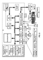
- FIG. 1 illustrates VPN architecture for containers and VMs, in accordance with the exemplary embodiment.
- Hardware nodes 20 A, 20 B and 20 C are connected by a network 102 .
- the node 20 A has containers 107 A and 107 C and VM 107 B running on it.
- the node 20 B has VMs 106 A and 106 B running on it and the node 20 C has containers 104 A- 104 D running on it.
- the node 20 D has a VM 109 implemented on it.
- a VPN #1 includes containers 104 A and 104 B and 107 A and VMs 107 B and 106 A.
- a VPN #2 includes a container 107 C and a VM 106 B.
- the containers and the VMs are connected to the network 102 via software switches that serve as a self-learning programmable module.
- programmable software switches 108 A- 108 D are implemented on each hardware node.
- a packet 110 comes from the container 107 A.
- the packet has a source address 111 in the header and VPN identifier as a metadata accessible by parsing packet.
- the ARP Proxy is aware of the location of the traffic's destination.
- the ARP Proxy offers its own MAC address in reply, effectively saying “send it to me, and I will get it to where it needs to go.”
- Serving as an ARP Proxy for another host effectively directs LAN traffic to the Proxy.
- the “captured” traffic is, then, routed by the Proxy to the intended destination via another interface or via a tunnel.
- the process, which results in the node responding with its own MAC address to an ARP request for a different IP address for proxying purposes, is sometimes referred to as “publishing.”
- the ARP used as an example of broadcast protocol and any other broadcast protocol and the Proxy can be used.
- the packet is sent to a common network 102 .
- the switches 108 B, 108 C and 108 D receive the multicast packet 110 through the network 102 and analyze it. The switches check if the destination containers/VMs corresponding to the VPN# are running on the respective hardware node and then either drop the packets or redirect them as described above.
- the packet will reach the node and will be discarded by the switch 108 D, since there are no VPNs that include the VM 109 .
- the software implemented programmable intelligent switches are located after hardware LAN cards or network adapters.
- an exemplary system for implementing the invention includes a general purpose computing device in the form of a computer system/network node 20 or the like including a processing unit 21 , a system memory 22 , and a system bus 23 that couples various system components including the system memory to the processing unit 21 .
- the system bus 23 may be any of several types of bus structures including a memory bus or memory controller, a peripheral bus, and a local bus using any of a variety of bus architectures.
- the system memory includes read-only memory (ROM) 24 and random access memory (RAM) 25 .
- ROM read-only memory
- RAM random access memory
- the computer 20 may further include a hard disk drive 27 for reading from and writing to a hard disk, not shown, a magnetic disk drive 28 for reading from or writing to a removable magnetic disk 29 , and an optical disk drive 30 for reading from or writing to a removable optical disk 31 such as a CD-ROM, DVD-ROM or other optical media.
- the hard disk drive 27 , magnetic disk drive 28 , and optical disk drive 30 are connected to the system bus 23 by a hard disk drive interface 32 , a magnetic disk drive interface 33 , and an optical drive interface 34 , respectively.
- the drives and their associated computer-readable media provide non-volatile storage of computer readable instructions, data structures, program modules and other data for the computer 20 .
- a number of program modules may be stored on the hard disk, magnetic disk 29 , optical disk 31 , ROM 24 or RAM 25 , including an operating system 35 .
- the computer 20 includes a file system 36 associated with or included within the operating system 35 , one or more application programs 37 , other program modules 38 and program data 39 .
- a user may enter commands and information into the computer 20 through input devices such as a keyboard 40 and pointing device 42 .
- Other input devices may include a microphone, joystick, game pad, satellite dish, scanner or the like.
- serial port interface 46 that is coupled to the system bus, but may be connected by other interfaces, such as a parallel port, game port or universal serial bus (USB).
- a monitor 47 or other type of display device is also connected to the system bus 23 via an interface, such as a video adapter 48 .
- personal computers typically include other peripheral output devices (not shown), such as speakers and printers.
- the computer 20 may operate in a networked environment using logical connections to one or more remote computers 49 .
- the remote computer (or computers) 49 may be another computer, a server, a router, a network PC, a peer device or other common network node, and typically includes many or all of the elements described above relative to the computer 20 , although only a memory storage device 50 has been illustrated.
- the logical connections include a local area network (LAN) 51 and a wide area network (WAN) 52 .
- LAN local area network
- WAN wide area network
- the computer 20 When used in a LAN networking environment, the computer 20 is connected to the local network 51 through a network interface or adapter 53 . When used in a WAN networking environment, the computer 20 typically includes a modem 54 or other means for establishing communications over the wide area network 52 , such as the Internet.
- the modem 54 which may be internal or external, is connected to the system bus 23 via the serial port interface 46 .
- program modules depicted relative to the computer 20 may be stored in the remote memory storage device. It will be appreciated that the network connections shown are exemplary and other means of establishing a communications link between the computers may be used.
Landscapes
- Engineering & Computer Science (AREA)
- Computer Networks & Wireless Communication (AREA)
- Signal Processing (AREA)
- Software Systems (AREA)
- Theoretical Computer Science (AREA)
- General Engineering & Computer Science (AREA)
- Computer Security & Cryptography (AREA)
- Multimedia (AREA)
- Physics & Mathematics (AREA)
- General Physics & Mathematics (AREA)
- Computer Hardware Design (AREA)
- Computing Systems (AREA)
- Data Exchanges In Wide-Area Networks (AREA)
Abstract
Description
Claims (11)
Priority Applications (3)
| Application Number | Priority Date | Filing Date | Title |
|---|---|---|---|
| US14/710,876 US9485219B1 (en) | 2015-05-13 | 2015-05-13 | VPN for containers and virtual machines in local area networks |
| US15/333,379 US9548964B1 (en) | 2015-05-13 | 2016-10-25 | VPN for containers and virtual machines in local area networks |
| US15/399,880 US9716688B1 (en) | 2015-05-13 | 2017-01-06 | VPN for containers and virtual machines in local area networks |
Applications Claiming Priority (1)
| Application Number | Priority Date | Filing Date | Title |
|---|---|---|---|
| US14/710,876 US9485219B1 (en) | 2015-05-13 | 2015-05-13 | VPN for containers and virtual machines in local area networks |
Related Child Applications (1)
| Application Number | Title | Priority Date | Filing Date |
|---|---|---|---|
| US15/333,379 Division US9548964B1 (en) | 2015-05-13 | 2016-10-25 | VPN for containers and virtual machines in local area networks |
Publications (1)
| Publication Number | Publication Date |
|---|---|
| US9485219B1 true US9485219B1 (en) | 2016-11-01 |
Family
ID=57189492
Family Applications (2)
| Application Number | Title | Priority Date | Filing Date |
|---|---|---|---|
| US14/710,876 Active US9485219B1 (en) | 2015-05-13 | 2015-05-13 | VPN for containers and virtual machines in local area networks |
| US15/333,379 Active US9548964B1 (en) | 2015-05-13 | 2016-10-25 | VPN for containers and virtual machines in local area networks |
Family Applications After (1)
| Application Number | Title | Priority Date | Filing Date |
|---|---|---|---|
| US15/333,379 Active US9548964B1 (en) | 2015-05-13 | 2016-10-25 | VPN for containers and virtual machines in local area networks |
Country Status (1)
| Country | Link |
|---|---|
| US (2) | US9485219B1 (en) |
Cited By (1)
| Publication number | Priority date | Publication date | Assignee | Title |
|---|---|---|---|---|
| US20160371108A1 (en) * | 2015-06-16 | 2016-12-22 | Vmware, Inc. | Reservation for a multi-machine application |
Citations (12)
| Publication number | Priority date | Publication date | Assignee | Title |
|---|---|---|---|---|
| US6947384B2 (en) * | 1999-01-11 | 2005-09-20 | Hewlett Packard Development Company, L.P. | MAC address learning and propagation in load balancing switch protocols |
| US7333491B2 (en) * | 2002-04-30 | 2008-02-19 | Realtek Semiconductor Corp. | Method and apparatus for packet forwarding in a switch controller |
| US20110243142A1 (en) * | 2010-03-31 | 2011-10-06 | Brocade Communications Systems, Inc. | Ingress and egress switch which determines services related to an incoming packet |
| US20120054367A1 (en) * | 2010-08-24 | 2012-03-01 | Ramakrishnan Kadangode K | Methods and apparatus to migrate virtual machines between distributive computing networks across a wide area network |
| US20130036416A1 (en) * | 2011-08-05 | 2013-02-07 | Vmware, Inc. | Detecting and correcting network interruptions using network address translation |
| US20140044130A1 (en) * | 2012-08-09 | 2014-02-13 | International Business Machines Corporation | Avoiding unknown unicast floods resulting from mac address table overflows |
| US20140122675A1 (en) * | 2012-10-29 | 2014-05-01 | Oracle International Corporation | Network virtualization over infiniband |
| US20150003463A1 (en) * | 2013-06-28 | 2015-01-01 | Futurewei Technologies, Inc. | Multiprotocol Label Switching Transport for Supporting a Very Large Number of Virtual Private Networks |
| US20150381493A1 (en) * | 2014-06-30 | 2015-12-31 | Juniper Networks, Inc. | Service chaining across multiple networks |
| US9319317B1 (en) * | 2014-01-31 | 2016-04-19 | Adtran, Inc. | Systems and methods for disseminating addresses in distributed switching environments |
| US20160127229A1 (en) * | 2014-10-29 | 2016-05-05 | Metaswitch Networks Ltd | Packet data routing |
| US20160179437A1 (en) * | 2014-12-17 | 2016-06-23 | Vmware, Inc. | Consistent replication of virtual computing instance data |
-
2015
- 2015-05-13 US US14/710,876 patent/US9485219B1/en active Active
-
2016
- 2016-10-25 US US15/333,379 patent/US9548964B1/en active Active
Patent Citations (12)
| Publication number | Priority date | Publication date | Assignee | Title |
|---|---|---|---|---|
| US6947384B2 (en) * | 1999-01-11 | 2005-09-20 | Hewlett Packard Development Company, L.P. | MAC address learning and propagation in load balancing switch protocols |
| US7333491B2 (en) * | 2002-04-30 | 2008-02-19 | Realtek Semiconductor Corp. | Method and apparatus for packet forwarding in a switch controller |
| US20110243142A1 (en) * | 2010-03-31 | 2011-10-06 | Brocade Communications Systems, Inc. | Ingress and egress switch which determines services related to an incoming packet |
| US20120054367A1 (en) * | 2010-08-24 | 2012-03-01 | Ramakrishnan Kadangode K | Methods and apparatus to migrate virtual machines between distributive computing networks across a wide area network |
| US20130036416A1 (en) * | 2011-08-05 | 2013-02-07 | Vmware, Inc. | Detecting and correcting network interruptions using network address translation |
| US20140044130A1 (en) * | 2012-08-09 | 2014-02-13 | International Business Machines Corporation | Avoiding unknown unicast floods resulting from mac address table overflows |
| US20140122675A1 (en) * | 2012-10-29 | 2014-05-01 | Oracle International Corporation | Network virtualization over infiniband |
| US20150003463A1 (en) * | 2013-06-28 | 2015-01-01 | Futurewei Technologies, Inc. | Multiprotocol Label Switching Transport for Supporting a Very Large Number of Virtual Private Networks |
| US9319317B1 (en) * | 2014-01-31 | 2016-04-19 | Adtran, Inc. | Systems and methods for disseminating addresses in distributed switching environments |
| US20150381493A1 (en) * | 2014-06-30 | 2015-12-31 | Juniper Networks, Inc. | Service chaining across multiple networks |
| US20160127229A1 (en) * | 2014-10-29 | 2016-05-05 | Metaswitch Networks Ltd | Packet data routing |
| US20160179437A1 (en) * | 2014-12-17 | 2016-06-23 | Vmware, Inc. | Consistent replication of virtual computing instance data |
Cited By (2)
| Publication number | Priority date | Publication date | Assignee | Title |
|---|---|---|---|---|
| US20160371108A1 (en) * | 2015-06-16 | 2016-12-22 | Vmware, Inc. | Reservation for a multi-machine application |
| US9804880B2 (en) * | 2015-06-16 | 2017-10-31 | Vmware, Inc. | Reservation for a multi-machine application |
Also Published As
| Publication number | Publication date |
|---|---|
| US9548964B1 (en) | 2017-01-17 |
Similar Documents
| Publication | Publication Date | Title |
|---|---|---|
| US12218956B2 (en) | Providing a virtual security appliance architecture to a virtual cloud infrastructure | |
| US10547463B2 (en) | Multicast helper to link virtual extensible LANs | |
| US11516037B2 (en) | Methods to optimize multicast routing in overlay networks | |
| US11665088B2 (en) | Assisted replication in software defined network | |
| US11888899B2 (en) | Flow-based forwarding element configuration | |
| US11102079B2 (en) | Cross-regional virtual network peering | |
| CN109561108B (en) | Policy-based container network resource isolation control method | |
| CN107332812B (en) | Method and device for realizing network access control | |
| US10999195B1 (en) | Multicast VPN support in data centers using edge replication tree | |
| US9716688B1 (en) | VPN for containers and virtual machines in local area networks | |
| US11895030B2 (en) | Scalable overlay multicast routing | |
| WO2023168287A1 (en) | Synchronizing dynamic host configuration protocol snoop information | |
| US9548964B1 (en) | VPN for containers and virtual machines in local area networks | |
| US20240243942A1 (en) | Multicast group membership control for a container environment |
Legal Events
| Date | Code | Title | Description |
|---|---|---|---|
| AS | Assignment |
Owner name: PARALLELS IP HOLDINGS GMBH, SWITZERLAND Free format text: ASSIGNMENT OF ASSIGNORS INTEREST;ASSIGNORS:EMELYANOV, PAVEL;BOTTOMLEY, JAMES;SIGNING DATES FROM 20150506 TO 20150512;REEL/FRAME:035627/0670 |
|
| STCF | Information on status: patent grant |
Free format text: PATENTED CASE |
|
| AS | Assignment |
Owner name: PARALLELS INTERNATIONAL GMBH, SWITZERLAND Free format text: MERGER;ASSIGNOR:PARALLELS IP HOLDINGS GMBH;REEL/FRAME:040510/0864 Effective date: 20160630 |
|
| AS | Assignment |
Owner name: VIRTUOZZO INTERNATIONAL GMBH, SWITZERLAND Free format text: ASSIGNMENT OF ASSIGNORS INTEREST;ASSIGNOR:PARALLELS INTERNATIONAL GMBH;REEL/FRAME:044756/0294 Effective date: 20180123 |
|
| MAFP | Maintenance fee payment |
Free format text: PAYMENT OF MAINTENANCE FEE, 4TH YEAR, LARGE ENTITY (ORIGINAL EVENT CODE: M1551); ENTITY STATUS OF PATENT OWNER: LARGE ENTITY Year of fee payment: 4 |
|
| AS | Assignment |
Owner name: WILMINGTON TRUST (LONDON) LIMITED, UNITED KINGDOM Free format text: SECURITY INTEREST IN TRADEMARK, PATENT, AND COPYRIGHT RIGHTS;ASSIGNORS:VIRTUOZZO INTERNATIONAL GMBH;ONAPP LIMITED;REEL/FRAME:062206/0557 Effective date: 20221221 |
|
| MAFP | Maintenance fee payment |
Free format text: PAYMENT OF MAINTENANCE FEE, 8TH YEAR, LARGE ENTITY (ORIGINAL EVENT CODE: M1552); ENTITY STATUS OF PATENT OWNER: LARGE ENTITY Year of fee payment: 8 |