US9483199B1 - Data deduplication using multiple devices - Google Patents
Data deduplication using multiple devices Download PDFInfo
- Publication number
- US9483199B1 US9483199B1 US14/462,263 US201414462263A US9483199B1 US 9483199 B1 US9483199 B1 US 9483199B1 US 201414462263 A US201414462263 A US 201414462263A US 9483199 B1 US9483199 B1 US 9483199B1
- Authority
- US
- United States
- Prior art keywords
- data
- logical units
- blocks
- logical
- san
- Prior art date
- Legal status (The legal status is an assumption and is not a legal conclusion. Google has not performed a legal analysis and makes no representation as to the accuracy of the status listed.)
- Active, expires
Links
- 238000003860 storage Methods 0.000 claims abstract description 160
- 238000013500 data storage Methods 0.000 claims abstract description 85
- 238000000034 method Methods 0.000 claims abstract description 31
- 230000004044 response Effects 0.000 claims description 14
- 238000005192 partition Methods 0.000 claims description 10
- 238000000638 solvent extraction Methods 0.000 claims description 8
- 238000013144 data compression Methods 0.000 description 22
- 238000013507 mapping Methods 0.000 description 17
- 230000008569 process Effects 0.000 description 15
- 238000010586 diagram Methods 0.000 description 14
- 230000006870 function Effects 0.000 description 11
- 238000012545 processing Methods 0.000 description 10
- 238000007726 management method Methods 0.000 description 8
- 238000004891 communication Methods 0.000 description 7
- 238000004590 computer program Methods 0.000 description 7
- 238000004422 calculation algorithm Methods 0.000 description 6
- 238000007906 compression Methods 0.000 description 6
- 230000006835 compression Effects 0.000 description 6
- 230000001186 cumulative effect Effects 0.000 description 5
- 230000009286 beneficial effect Effects 0.000 description 3
- 238000013515 script Methods 0.000 description 3
- 230000008901 benefit Effects 0.000 description 2
- 230000003287 optical effect Effects 0.000 description 2
- 238000005457 optimization Methods 0.000 description 2
- 238000012913 prioritisation Methods 0.000 description 2
- 238000000926 separation method Methods 0.000 description 2
- 238000012546 transfer Methods 0.000 description 2
- 230000002776 aggregation Effects 0.000 description 1
- 238000004220 aggregation Methods 0.000 description 1
- 238000013459 approach Methods 0.000 description 1
- 230000001413 cellular effect Effects 0.000 description 1
- 230000008859 change Effects 0.000 description 1
- 238000012217 deletion Methods 0.000 description 1
- 230000037430 deletion Effects 0.000 description 1
- 230000007613 environmental effect Effects 0.000 description 1
- 239000000835 fiber Substances 0.000 description 1
- 230000007774 longterm Effects 0.000 description 1
- 230000014759 maintenance of location Effects 0.000 description 1
- 238000010295 mobile communication Methods 0.000 description 1
- 230000000644 propagated effect Effects 0.000 description 1
- 239000004065 semiconductor Substances 0.000 description 1
- 239000000758 substrate Substances 0.000 description 1
Images


Classifications
-
- G—PHYSICS
- G06—COMPUTING; CALCULATING OR COUNTING
- G06F—ELECTRIC DIGITAL DATA PROCESSING
- G06F3/00—Input arrangements for transferring data to be processed into a form capable of being handled by the computer; Output arrangements for transferring data from processing unit to output unit, e.g. interface arrangements
- G06F3/06—Digital input from, or digital output to, record carriers, e.g. RAID, emulated record carriers or networked record carriers
- G06F3/0601—Interfaces specially adapted for storage systems
- G06F3/0602—Interfaces specially adapted for storage systems specifically adapted to achieve a particular effect
- G06F3/0608—Saving storage space on storage systems
-
- G—PHYSICS
- G06—COMPUTING; CALCULATING OR COUNTING
- G06F—ELECTRIC DIGITAL DATA PROCESSING
- G06F3/00—Input arrangements for transferring data to be processed into a form capable of being handled by the computer; Output arrangements for transferring data from processing unit to output unit, e.g. interface arrangements
- G06F3/06—Digital input from, or digital output to, record carriers, e.g. RAID, emulated record carriers or networked record carriers
- G06F3/0601—Interfaces specially adapted for storage systems
- G06F3/0602—Interfaces specially adapted for storage systems specifically adapted to achieve a particular effect
- G06F3/0604—Improving or facilitating administration, e.g. storage management
-
- G—PHYSICS
- G06—COMPUTING; CALCULATING OR COUNTING
- G06F—ELECTRIC DIGITAL DATA PROCESSING
- G06F3/00—Input arrangements for transferring data to be processed into a form capable of being handled by the computer; Output arrangements for transferring data from processing unit to output unit, e.g. interface arrangements
- G06F3/06—Digital input from, or digital output to, record carriers, e.g. RAID, emulated record carriers or networked record carriers
- G06F3/0601—Interfaces specially adapted for storage systems
- G06F3/0628—Interfaces specially adapted for storage systems making use of a particular technique
- G06F3/0638—Organizing or formatting or addressing of data
- G06F3/064—Management of blocks
- G06F3/0641—De-duplication techniques
-
- G—PHYSICS
- G06—COMPUTING; CALCULATING OR COUNTING
- G06F—ELECTRIC DIGITAL DATA PROCESSING
- G06F3/00—Input arrangements for transferring data to be processed into a form capable of being handled by the computer; Output arrangements for transferring data from processing unit to output unit, e.g. interface arrangements
- G06F3/06—Digital input from, or digital output to, record carriers, e.g. RAID, emulated record carriers or networked record carriers
- G06F3/0601—Interfaces specially adapted for storage systems
- G06F3/0668—Interfaces specially adapted for storage systems adopting a particular infrastructure
- G06F3/067—Distributed or networked storage systems, e.g. storage area networks [SAN], network attached storage [NAS]
-
- G—PHYSICS
- G06—COMPUTING; CALCULATING OR COUNTING
- G06F—ELECTRIC DIGITAL DATA PROCESSING
- G06F3/00—Input arrangements for transferring data to be processed into a form capable of being handled by the computer; Output arrangements for transferring data from processing unit to output unit, e.g. interface arrangements
- G06F3/06—Digital input from, or digital output to, record carriers, e.g. RAID, emulated record carriers or networked record carriers
- G06F3/0601—Interfaces specially adapted for storage systems
- G06F3/0668—Interfaces specially adapted for storage systems adopting a particular infrastructure
- G06F3/0671—In-line storage system
- G06F3/0683—Plurality of storage devices
- G06F3/0689—Disk arrays, e.g. RAID, JBOD
-
- G—PHYSICS
- G06—COMPUTING; CALCULATING OR COUNTING
- G06F—ELECTRIC DIGITAL DATA PROCESSING
- G06F3/00—Input arrangements for transferring data to be processed into a form capable of being handled by the computer; Output arrangements for transferring data from processing unit to output unit, e.g. interface arrangements
- G06F3/06—Digital input from, or digital output to, record carriers, e.g. RAID, emulated record carriers or networked record carriers
- G06F2003/0697—Digital input from, or digital output to, record carriers, e.g. RAID, emulated record carriers or networked record carriers device management, e.g. handlers, drivers, I/O schedulers
Definitions
- This description relates to storing data in a data storage system.
- Computers can be used to store, access, and modify data within a data storage system.
- a system for managing data-related requests between a host and a storage area network (SAN) device is configured to receive data describing a first set of logical units of the SAN device, the first set of logical units together representing a total quantity of logical data storage that is greater than a total quantity of physical data storage available on the SAN device, where at least some pages of the first set of logical units are not allocated to the physical data storage; present one or more second logical units to the host, wherein the second logical units correspond to one or more logical units of the first set of logical units; receive, from the host, a request to write data to a particular second logical unit, where the request identifies a portion of data and a location of the particular second logical unit; partition the particular portion of data into one or more blocks; create an index for the particular portion of data, the index comprising, for each of the blocks, an identity of the block and a corresponding location field; identify, from among the blocks, at least one duplicative block that is already stored in the
- Implementations of the first aspect may include one or more of the following features.
- the system is configured to generate the new request based on a strategy for increasing an amount of data that can be stored on the SAN device.
- the strategy is based on the data describing logical units of the SAN device.
- the strategy is based on a determination that, if the new request does not include duplicative blocks, the quantity of pages of the logical units not allocated to the physical data storage can be increased.
- the new request further comprises an indication to the SAN device to write the remaining blocks to the logical unit by, at least in part, prioritizing the filling of pages of the logical unit.
- Prioritizing the filling of pages of the logical unit comprises, when writing data to a page, selecting a page that already contains data instead of selecting a page that does not already contain data.
- the system is configured to compress the particular portion of data after partitioning the particular portion of data into one or more blocks.
- the system is configured to compress the particular portion of data after partitioning the particular portion of data into one or more blocks.
- Data describing a first set of logical units of the SAN device is received from the SAN device.
- a data deduplication device is configured for receiving data describing logical units of a storage area network (SAN) device, the logical units together representing a total quantity of logical data storage that is greater than a total quantity of physical data storage available on the SAN device, where at least some pages of the logical units are not allocated to the physical data storage; receiving requests to write data to the SAN device, where each request identifies a particular location of one of the logical units; and increasing a quantity of the pages that are not allocated to the physical data storage by identifying, among the received requests, at least one request to write data that is already stored in the physical data storage but stored at a location other than the particular location specified by the request, and, in response, not storing the data as requested, but instead recording a pointer from the particular location specified by the request to the other location that already stores the data.
- SAN storage area network
- a method in general, includes presenting, to host devices, a quantity of logical data storage greater than physical data storage available on a storage area network (SAN) device, by deduplicating at least some of the data received from the host devices for storage at the SAN device in a manner that is coordinated with over-provisioning capability of the SAN device.
- SAN storage area network
- Implementations of the third aspect may include one or more of the following features.
- the logical data storage is presented to host devices by a device that does not manage the over-provisioning capability of the SAN device.
- Deduplicating at least some of the data received from the host devices for storage at the SAN device in a manner that is coordinated with over-provisioning capability of the SAN device comprises providing an indication to the SAN device to write blocks to a logical unit of the SAN device by, at least in part, prioritizing the filling of pages of the logical unit.
- a system for managing data-related requests between a host and a storage area network (SAN) device is configured to receive data describing a first set of logical units of the SAN device, the first set of logical units together representing a total quantity of logical data storage that is greater than a total quantity of physical data storage available on the SAN device, where at least some pages of the first set of logical units are not allocated to the physical data storage; present one or more second logical units to the host, wherein the second logical units correspond to one or more logical units of the first set of logical units; receive, from the host, a request to write data to a particular second logical unit, where the request identifies a portion of data and a location of the particular second logical unit; partition the particular portion of data into one or more blocks; create an index for the particular portion of data, the index comprising, for each of the blocks, an identity of the block and a corresponding location field; transmit, to the SAN device, a new request to write data, where
- Implementations of the fourth aspect may include one or more of the following features.
- the system is configured to generate the new request based on a strategy for increasing an amount of data that can be stored on the SAN device.
- the strategy is based on the data describing logical units of the SAN device.
- the strategy is based on a determination that, if the new request does not include duplicative blocks, the quantity of pages of the logical units not allocated to the physical data storage can be increased.
- Prioritizing the filling of pages of the logical unit comprises, when writing data to a page, selecting a page that already contains data instead of selecting a page that does not already contain data.
- the system is configured to compress the particular portion of data after partitioning the particular portion of data into one or more blocks. Data describing a first set of logical units of the SAN device is received from the SAN device.
- FIG. 1 is a block diagram of a system that stores, retrieves, and modifies data.
- FIG. 2 is a block diagram of a system that includes several host devices, a data deduplication device, a storage area network (SAN) device, and several storage devices.
- SAN storage area network
- FIG. 3A is a block diagram of a request to write data.
- FIG. 3B is a block diagram of a data deduplication operation.
- FIG. 3C is a block diagram of a new request to write data.
- FIG. 3D is a block diagram of an index.
- FIG. 4 is a block diagram of a request to retrieve data.
- FIG. 5A is a block diagram of a logical unit of a SAN device.
- FIG. 5B is a block diagram of a request to write data to a logical unit of a SAN device in a manner that prioritizes the filing of pages of the logical unit.
- FIG. 6 is a block diagram of a process for managing data-related requests between a host and a SAN device.
- FIG. 7 is a block diagram of a system that includes one or more host devices, one or more data deduplication devices, one or more SAN devices, and one or more physical storage devices interconnected through one or more network switches.
- FIG. 8 is a block diagram of an example computer system.
- a data deduplication system increases the amount of data that can be stored in a data storage system by identifying data that is (or would be) stored in duplicate in more than one location on the data storage system, deleting the data from at least one of the duplicate data locations, and pointing the duplicate data location(s) to the remaining location storing the data.
- Some data deduplication systems provide data deduplication functionality by managing data-related requests intended for a data storage system.
- a data deduplication system that manages data-related requests can be placed between host devices (e.g., user devices) and physical storage devices (e.g., disk drives, flash memory devices, etc.).
- the data deduplication system can then be used to handle data requests (e.g., requests to read or write data) between the host(s) and the physical storage.
- the data deduplication system can perform various functions in connection with storage of data on the physical storage devices. For example, the data deduplication system can perform logical unit mapping, data compression, data deduplication, thin provisioning, and over-provisioning.
- a logical unit is a representation of data storage that may not directly correspond to physical data storage such as physical disks. Instead, a logical unit may correspond to a portion of a physical data storage device such as a disk, and other logical units may share the same disk. Further, a logical unit may correspond to portions of multiple data storage devices, e.g., in a RAID array. Thin provisioning is the act of not allocating physical resources (e.g., physical blocks of a disk) to logical resources (e.g., a logical unit) until the physical resources are needed. Over-provisioning is the use of thin provisioning to give the appearance of having more physical resources than would be available if all of the logical resources were allocated to physical resources.
- a data deduplication system might receive a host's request to write data to a particular logical unit; in response, the data deduplication system might de-duplicate the data into non-duplicative blocks and write the blocks to an over-provisioned physical storage device that corresponds to the desired logical unit.
- a data deduplication system might receive a host's request to read data from a particular logical drive; in response, the data deduplication system might retrieve non-duplicative blocks from a physical storage device that corresponds to the desired logical unit, reconstruct the requested data from blocks, and transfer the data to the host.
- a single system need not perform all of these steps.
- a data deduplication system might only perform certain functions (e.g., data deduplication).
- Other functions e.g., logical drive mapping and over-provisioning
- another system e.g., another request management system, such as a storage area network system, or not at all.
- a data storage system might include two systems that manage requests related to data stored on the data storage system.
- a first system might perform data deduplication but not, for example, over-provisioning.
- the first system receives a request to write data to a particular logical drive; in response, the first system de-duplicates the data into non-duplicative blocks. These blocks are then passed to a second system that also manages data-related requests.
- the second system might perform logical drive mapping and over-provisioning.
- the second system receives blocks of data from the first system, maps the data request to an appropriate physical storage device, and writes the data blocks onto the physical storage device.
- the second system might over-provision the physical storage devices, for example by presenting a usable storage capacity that is greater than what is actually available on the physical storage devices, under the assumption that not every logical unit will be at full capacity.
- the two systems described here could be portions of the same computing device (e.g., software systems executing on the computing device), or, in some examples, could be two separate devices.
- the first system may be a deduplication device
- the second system may be a storage area network (SAN) device.
- the deduplication system can receive requests destined for the SAN device and provide deduplication in a manner that works with over-provisioning capabilities of the SAN device without having to manage the over-provisioning directly.
- separating functionality between multiple systems might allow a user to modularly add functionality to an overall data storage system, or remove functionality from the overall data storage system.
- an existing system might have a request management system that only provides logical drive mapping and over-provisioning.
- a deduplication system can be modularly added to this system, such that data write requests from a host are, for example, first de-duplicated into non-duplicative blocks by the deduplication system and then transmitted to the request management system for further processing.
- different functions can be performed at different times and/or by different “layers” of the overall system.
- multiple request management systems might be capable of performing one of more of the same functions. However, in some cases, it might be beneficial to perform certain functions on only one “layer” of the overall system. As an example, while two request management systems might each be capable of performing over-provisioning, it might be beneficial to provide over-provisioning using only one request management system (e.g., the request management system that most directly interacts with the physical storage devices), such that only a single “layer” of over-provisioning needs to be monitored and managed.
- the deduplication system can provide optimization (e.g., storing smaller amounts of data than would be stored if deduplication were not used) for a device that offers its own thin provisioning/over-provisioning in a way that doesn't require thin provisioning/over-provisioning to be managed at the optimization level.
- FIG. 1 is a block diagram of a system 100 that stores, retrieves, and modifies data.
- the system 100 includes one or more host devices 102 , one or more data deduplication devices 104 , one or more storage area network (SAN) devices 106 , and one or more storage devices 108 .
- a user interacts with a host device 102 in order to create, delete, and modify data.
- data from the host device 102 is transferred to a data deduplication device 104 , then transferred to a SAN device 106 , and then transferred to a physical storage device 108 where it is stored for future retrieval.
- data is transferred from a physical storage device 108 to a SAN device 106 , then transferred to a data deduplication device 104 , then transferred to the host device 102 where it is made available to the user. Any revisions to the data are transferred from the host device 102 to the physical storage device 108 via the data deduplication devices 104 and SAN devices 106 , in a manner similar to the storage of data described above.
- Various components of system 100 can be interconnected such that they can each transmit data to and receive data from other interconnected components.
- host devices 102 are interconnected with data deduplication device 104
- data deduplication devices 104 are interconnected with host devices 102 and SAN devices 106
- SAN devices 106 are interconnected with data deduplication devices 104 and physical storage devices 108
- physical storage devices 108 are interconnected with SAN devices 106 .
- the interconnection of devices can be implemented in a variety of ways.
- some devices can be interconnected to other devices through a local area network (LAN), through a wide area network (WAN), such as the Internet, or through a Storage Area Network (SAN), such as a Fibre Channel network, an iSCSI network, an ATA over an Ethernet network, or a HyperSCSI network.
- LAN local area network
- WAN wide area network
- SAN Storage Area Network
- Fibre Channel network such as a Fibre Channel network
- iSCSI network such as an iSCSI network
- ATA over an Ethernet network
- HyperSCSI network such as a Fibre Channel network
- Other types of networks can also be used, for instance a telephone network (cellular and/or wired), Bluetooth network, near field communications (NFC) network, or other network capable of transmitting data between interconnected systems.
- NFC near field communications
- two or more networks may be interconnected, such that devices connected to one network can communicate with devices connected to another network.
- some devices can be directly connected to other devices, for example through a serial bus connection or other direct connection
- one or more of the components can be managed by a cloud storage interface.
- the physical storage devices 108 can be distributed over one or more networks, and the cloud storage interface can manage data-related requests to and from the physical storage devices 108 .
- the SAN device 106 can be a cloud gateway storage device that functions as a communications node between the physical storage devices 108 and the host devices 102 , and provides a cloud storage interface for the physical storage devices 108 .
- the host devices 102 are devices that process data (e.g., create, delete, or modify data).
- users can interact with the host devices 102 through an appropriate user interface in order to create, delete, and modify data.
- the host devices 102 can be client computing devices, such as desktop computers, laptops, personal data assistants (PDAs), smartphones, tablet computers, or any other computing device that allows a user to view or interact with data.
- the host devices 102 do not directly interact with users, and instead indirectly receive instructions and data from users through an intermediary system.
- the host devices 102 can be computing devices such as server computers that indirectly receive instructions and data from users via client computing devices.
- the host devices 102 need not receive instructions and data from users at all.
- the host device 102 can be automated, such that they create, delete, and modify data without substantial input from a user.
- the physical storage devices 108 are devices that store information in a format that can be readily understood by one or more computer systems.
- the physical storage devices 108 can be disk accessing storage devices (e.g., hard disk drives), non-volatile random access memory (RAM) devices, volatile RAM devices, flash memory devices, tape drives, memory cards, or any other devices capable of retaining information for future retrieval.
- information from the host devices 102 are stored in the physical storage devices 108 , and information requested from the host devices 102 are retrieved from the physical storage devices 108 .
- data deduplication devices 104 and SAN devices 106 can be used to process data requests and data transfers between the host devices 102 and the physical storage devices 108 .
- data deduplication devices 104 increase the amount of data that can be stored in a data storage system by identifying data that is (or would be) stored in duplicate in more than one location on the data storage system, deleting the data from at least one of the duplicate data locations (or not storing the data again if the data is already stored at another location), and creating references from the duplicate data location(s) to the remaining location storing the data.
- data deduplication devices 104 manages data-related requests between the host devices 102 and the physical storage devices 108 .
- a SAN device 106 can also perform tasks similar to those of the data deduplication devices 104 , or can perform particular tasks not performed by the data deduplication devices 104 .
- the SAN devices 106 might perform logical unit mapping, thin provisioning, and/or over-provisioning.
- Logical unit mapping refers to the mapping of a logical unit to its corresponding physical data storage devices.
- a logical unit is a representation of data storage that may not directly correspond to physical data storage such as a physical disk. Instead, a logical unit may correspond to a portion of a physical data storage device such as a disk, and other logical units may share the same disk. Further, a logical unit may correspond to portions of multiple data storage devices, e.g., portions of multiple devices arranged in a RAID array.
- Logical unit mapping can be used to describe the relationship between a logical unit and its corresponding data storage, such that requests (e.g., data storage requests or data retrieval by host devices 102 ) referencing particular logical units can be converted into requests referencing one or more corresponding portions of the physical storage devices (e.g., the physical storage devices 108 ).
- requests e.g., data storage requests or data retrieval by host devices 102
- referencing particular logical units can be converted into requests referencing one or more corresponding portions of the physical storage devices (e.g., the physical storage devices 108 ).
- Thin provisioning is the act of not allocating physical resources (e.g., physical portions of a disk) to logical resources (e.g., a logical unit) until the physical resources are needed.
- physical resources e.g., physical portions of a disk
- logical resources e.g., a logical unit
- Thin provisioning is the act of not allocating physical resources (e.g., physical portions of a disk) to logical resources (e.g., a logical unit) until the physical resources are needed.
- a physical storage device having 100 GB of storage capacity might be provisioned into ten logical units, each presenting a storage capacity of 10 GB.
- This physical storage can be “thin provisioned,” such that even though each of the logical units are presented with 10 GB of storage capacity, storage portions of the physical storage device are not allocated to each of the logical units until these portions of the physical storage device are actually needed.
- portions of the physical storage device can be, for example, allocated to “pages” of a logical unit, where each page represents the minimum amount of storage than can be allocated for the purposes of thin provisioning. Therefore, when no data is stored on any of the logical units, portions of the physical storage device are not substantially allocated to any pages of the logical units. As data is written to each of the logical units, portions of the physical storage are incrementally allocated to the pages of the logical units to fulfill each data storage request.
- a page corresponds to an aggregation of sequential blocks.
- Over-provisioning is the use of thin provisioning to give the appearance of having more physical resources than would be available if all of the logical resources were allocated to physical resources.
- a physical storage device having 100 GB of storage capacity might be over-provisioned into twenty logical units, each presenting a storage capacity of 10 GB.
- the logical units cumulatively present 200 GB of available storage capacity, even though the underlying physical storage device only has a storage capacity of 100 GB.
- the physical storage device is thin provisioned, when no data is stored on any of the logical units, none of the portions of the physical storage device are allocated to any pages of the logical units, regardless of the storage capacity presented by each of the logical units.
- portions of the physical storage device are incrementally allocated to the pages of the logical units to fulfill each data storage request.
- an over-provisioned physical storage device can fulfill data storage requests corresponding to each of the logical units, so long as the cumulative data across all of the logical units does not exceed the physical storage limits of the physical storage device.
- Multiple physical storage devices can be collectively thin provisioned or over-provisioned.
- a collection of ten physical storage devices, each having 100 GB of storage capacity might be over-provisioned into 100 logical units, each presenting a storage capacity of 100 GB.
- the logical units cumulatively present 10 TB of available storage capacity, even though the underlying physical storage devices only have a cumulative storage capacity of 1 TB.
- additional physical storage devices can be added to increase the cumulative storage capacity of the collection of physical storage devices.
- the data deduplication devices 104 and the SAN devices 106 can work in conjunction in order to collectively provide data compression, data deduplication, logical unit mapping, thin provisioning, and/or over-provisioning between the host devices 102 and the physical storage devices 108 .
- the system 200 includes several host devices 102 a - d , a data deduplication device 104 a , a SAN device 106 a , and several storage devices 108 a - d.
- the SAN device 106 provides logical unit mapping, thin provisioning, and over-provisioning for the physical storage devices 108 a - d .
- the SAN device 106 a provides logical unit mapping, thin provisioning, and over-provisioning of the physical storage devices 108 a - d into the logical units 206 a - d , such that any requests pertaining to one of the logical units 206 a - d are mapped to one or more corresponding physical storage units 108 a - d , and vice versa.
- the SAN 106 a can logically map and over-provision a single physical storage device into a single logical unit.
- the physical storage device 108 a can include a hard disk drive 208 a having a physical storage capacity of 100 GB.
- the SAN 106 a maps a single logical unit 206 a to the physical storage device 108 a , and over-provisions the physical storage device 108 a , such that the 100 GB storage capacity of the hard disk drive 208 a is provisioned into a 1000 GB storage capacity in the logical unit 206 a.
- the SAN 106 a can logically map and over-provision multiple physical storage devices into a single logical unit.
- the physical storage devices 108 b - c can each include a hard disk drive 208 b - c each having a physical storage capacity of 100 GB.
- the SAN 106 a maps a single logical unit 206 b to the physical storages device 108 b - c , and over-provisions the physical storage devices 108 b - c , such that the 200 GB cumulative storage capacity of the hard disk drives 208 b - c is provisioned into a 2000 GB storage capacity in the logical unit 206 b.
- the SAN 106 a can logically map and over-provision a single physical storage device into a multiple logical units.
- the physical storage device 108 d can include a hard disk drive 208 d having a physical storage capacity of 100 GB.
- the SAN 106 a maps multiple logical units 206 c - d to the physical storage device 108 d , and over-provisions the physical storage device 108 d , such that the 100 GB storage capacity of the hard disk drive 208 d is provisioned into a logical unit 206 c having a 100 GB storage capacity and a logical unit 206 d having a 1000 GB storage capacity.
- the SAN 106 a can logically map and over-provision any number of physical storage devices into any number of logical units.
- the data deduplication device 104 a is situated between the hosts 102 a - d and the SAN device 106 a , such that it receives data requests (e.g., requests to read, write, or erase data) from the hosts 102 a - d , interprets the requests, creates a new request, and transmits the new request to the SAN device 106 a .
- This new request can be used to implement various features, independent from the capabilities of the hosts 102 a - d and the SAN device 106 a.
- the SAN device 106 a performs logical mapping and over-provisioning, but does not perform data compression or data deduplication.
- requests from the hosts 102 a - d to write data to a logical unit of the SAN device 106 a are intercepted by the data deduplication device 104 a , which generates new data requests to provide data compression and/or data deduplication.
- the data deduplication device 104 a then transmits the new request to the SAN device 106 a , which writes the compressed and/or deduplicated data to one or more corresponding physical storage devices 108 a - d .
- the data deduplication device 104 a transparently generates new requests to write data in a manner that implements these features.
- requests from the hosts 102 a - d to retrieve data from the logical unit of the SAN device 106 a are intercepted by the data deduplication device 104 a , which generates new data requests to account for any data compression and/or data deduplication that may have been previously provided by data deduplication device 104 a during the storage of the requested data.
- the data deduplication device 104 a then transmits the new request to the SAN device 106 a .
- the retrieved data is passed from the SAN device 106 a , and is modified (e.g., decompressed or re-constructed from deduplicated data) by the data deduplication device 104 a to account for any data compression and/or data deduplication that may have been previously provided.
- the requested data is then returned to the host 102 a - d where it is made available for access.
- the data deduplication device 104 a transparently generates new requests to read data in a manner that implements these features.
- the data deduplication device does not provide thin provisioning or over-provisioning.
- the logical units 206 a - d of the SAN device 106 a have been logically mapped to the logical units 204 a - d of the data deduplication device 104 a in a manner that redistributes the storage capacities of the logical units 206 a - d
- the total storage capacity of the logical units 206 a - d of the SAN device 106 a is the same as the total storage capacity of the logical units 204 a - d of the data deduplication device 104 a .
- each logical unit 204 a - d of the data deduplication device 104 a is the same as the storage capacity of a corresponding logical unit 202 a - d of a host 102 a - d .
- thin provisioning and/or over-provisioning only occurs on a single “layer” of the system 200 (i.e., between the SAN device 106 a and the physical storage devices 108 a - d ).
- logical units are mapped into one or more other logical units, but are not thin provisioned or over-provisioned. Accordingly, in this example, the total presented capacity does not change during these logical mappings.
- a data deduplication device 104 can be situated between the hosts 102 and the SAN device 106 , such that it receives data requests from the hosts 102 , interprets the requests, creates a new request, and transmits the new request to the SAN device 106 .
- This new request can be used to implement various features independent from the capabilities of the hosts 102 and the SAN device 106 .
- the SAN device 106 might receive data and data-related requests from the hosts 102 , and provide logical mapping and over-provisioning to the physical storage devices 108 .
- a data deduplication device 104 can used to manage data and data-related requests between the hosts 102 and the SAN device 106 in order to provide data compression and data deduplication, even though the hosts 102 and the SAN device 106 might not be individually capable of providing these functions.
- the data deduplication device 104 receives, from the SAN device 106 , data describing logical units of the SAN device.
- This information can include, for example, information that describes the storage capacity of the logical unit, the identity of data stored on the logical unit (e.g., blocks, or portions, of data that are stored on the logical unit), the location of the data stored on the logical unit (e.g., the particular pages of the logical unit that store particular blocks of data), the location of free space on the logical unit (e.g., the location of pages of the logical unit that do not contain any data), and so forth.
- the logical units seen by the data deduplication device 104 might together represent a total quantity of logical data storage that is greater than a total quantity of physical data storage available on the SAN device, where at least some pages of the logical units are not allocated to the physical data storage devices 108 .
- the data deduplication device 104 might receive a request from the host 102 to write data to a particular logical unit of the SAN device 106 .
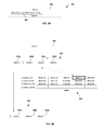
- FIG. 3A shows a conceptual example of a request 300 to write data.
- the request 300 might include, for example, a particular portion of data 302 to be written, and an instruction 304 to write the data 302 to a particular location of a logical unit.
- the instruction might specify a particular LUN presented by a data deduplication device 104 and a logical block address (LBA) that specifies the location within the LUN.
- LBA logical block address
- the data deduplication device 104 might perform data deduplication on the data 302 .
- FIG. 3B A conceptual example of these operations is shown in FIG. 3B .
- the data deduplication device 104 partitions the data 302 into one or more blocks.
- the data 302 is partitioned into several blocks 306 a - d .
- each block of data can be substantially the same size (e.g., have a uniform block size).
- some blocks of data can have a different size than other blocks of data (e.g., have a variable block size).
- Data can be partitioned according to certain observed properties of the data, and/or according to particular pre-defined parameters.
- data can be partitioned such that each block is of a certain pre-defined size.
- data can be parsed and partitioned based on certain properties of the parsed data. For instance, data might be parsed and partitioned when certain characteristics (e.g., particular sequences of bits) are observed.
- data might be parsed and hashed (e.g., using a hashing algorithm), and partitioned when certain characteristics in the hash value are observed (e.g., when particular hash values are observed).
- the data 302 is partitioned such that each block 306 a - d is of a particular pre-defined size.
- the data deduplication device 104 identifies, from among the blocks, duplicative blocks that are already stored in the physical data storage devices but stored at a location other than the location specified by the request. If any duplicate blocks are found, the data deduplication device 104 records, for each of the duplicative blocks, the other location that already stores the block, and deletes the duplicative blocks. For example, as shown in FIG. 3B , each of the blocks 306 a - d is compared against the blocks of a logical unit 308 . In some implementations, this comparison can be an exact byte-by-byte comparison between the blocks 306 a - d and the blocks of the logical unit 308 .
- this comparison need not be an exact byte-by-byte comparison, and can be instead be accelerated by a deduplication index.
- a deduplication index might include hash values of each block of the logical unit 308 , such that the hashes of blocks 306 a - d can be compared against the hashes of the blocks of the logical unit 308 in order to find duplicative data.
- the logical unit 308 can be, for example, one or more of the logical units 206 a - d of the SAN device 106 a .
- the logical unit 308 need not be the logical unit specified by the request 300 .
- the original request 300 specifies data to be written to a particular logical unit of the data deduplication device 104 a (i.e., “LUN 1”)
- each of the blocks 306 a - d is compared against the blocks stored in the pages of a corresponding logical unit 308 of a SAN device 106 to which “LUN 1” is mapped (i.e., “LUN 2”).
- LUN 1 data to be written to a particular logical unit of the data deduplication device 104 a
- locations 1-15 of the logical unit 308 are storing various blocks of unique data (indicated by different numerical block labels), while locations 16-20 are empty (indicated by the absence of labels).
- the block 306 c matches a block already stored in the logical unit 306 (i.e., the block stored in location 4 of the logical unit 308 ). Based on this match, the data deduplication device 104 records for the duplicative block 306 c , the other location that already stores the block (i.e, location 4 of the logical unit 308 ), and deletes the block 306 c .
- the resulting deduplicated data 310 retains each of the unique blocks 306 a , 306 b , and 306 d , but no longer has the duplicative block 306 c.
- a new write request is created based on the deduplicated data and the original request 300 .
- the data deduplication device 104 creates a new write request 312 .
- the new write request 312 might include, for example, the remaining blocks 306 a , 306 b , and 306 d to be written, and an instruction 314 to write the blocks 306 a , 306 b , and 306 d to the logical unit 308 corresponding to the logical unit specified by the original request 300 .
- the new write request 312 might specify that the remaining blocks be written to the corresponding logical unit 308 of the SAN device 106 a .
- This request is then transmitted to the SAN device 106 for processing, whereby the blocks 306 a , 306 b , and 306 d are written to the indicated logical unit 308 (i.e., locations 16-17 of the logical unit 308 ).
- the location of each of these blocks is recorded by the data deduplication device 104 .
- the block 306 c was duplicative of a block already stored in the logical unit 308 , it has not been written to the logical unit 308 .
- each block stored on the logical unit 306 can be unique.
- the blocks 306 a , 306 b , and 306 d are deleted from the data deduplication device 104 .
- the location of each block within the specified logical unit is recorded by the data deduplication device 104 .
- These locations can be stored, for example, in an index or other data structure for future retrieval.
- the index can be stored in various locations, depending on the implementation. For example, the index can be stored within the SAN device 106 , within the data duplication device 104 , or elsewhere.
- an index 316 might include identity information 318 pertaining to the subject data (e.g., the data 302 ).
- the index 316 might also include identity fields 320 and location fields 322 pertaining to each of the blocks of the subject data (e.g., the blocks 306 a - d ).
- the index 316 might also include information regarding the proper sequence of the blocks (e.g., by listing the identity fields 320 and the location fields 322 in a particular order). In this manner, after the creation of the new write request, and after the data has been written by the SAN device, the data deduplication device 104 retains information regarding the identity of particular data, and the identity, location, and sequence of the blocks that make up that particular data.
- the data deduplication device 104 can also retrieve data from one or more of the logical units of the SAN device 106 .
- the data deduplication device 104 can be situated between the hosts 102 and the SAN device 106 , such that it receives requests from the hosts 102 to retrieve data from the SAN device 106 .
- the data deduplication device 104 interprets the request, creates a new request, and transmits the new request to the SAN device 106 . If the data deduplication device 104 created an index when the data was initially written to the logical unit, the data deduplication device 104 can use that index to create the new request.
- the data deduplication device 104 might receive a request from the host 102 to retrieve data from a particular logical unit of the SAN device 106 .
- FIG. 4 shows a conceptual example of a request 400 to retrieve data.
- the request 400 might include, for example, an instruction 402 to retrieve particular data from a particular logical unit of the SAN device 106 .
- the requested data is the same data 302 that was written to the SAN device 106 in FIGS. 3A-D .
- the data deduplication device 104 uses the index 316 (which was created when the data was written to the logical unit) to retrieve the appropriate blocks from the corresponding logical unit.
- the index 316 might include identity information 318 pertaining to the subject data (e.g., the data 302 ), as well as identity fields 320 and location fields 322 pertaining to each of the blocks of the subject data (e.g., the blocks 306 a - d ).
- the index 316 might also include information regarding the proper sequence of the blocks (e.g., by listing the identity fields 320 and the location fields 322 in a particular order).
- the data deduplication device 104 creates a new request to the SAN device 106 , requesting the retrieval of the blocks 306 a - d identified in the index 316 .
- the data deduplication device 104 arranges the blocks 306 a - d into the appropriate order (e.g., in the sequence described in the index 316 ). Therefore, when recombined, the blocks 306 a - d form the data 302 . The data 302 is then transmitted to the host, thereby fulfilling the retrieval request 402 .
- the data deduplication device 104 allows a host device 102 to retrieve data that has been deduplicated, even though the host device 102 and the SAN device 106 might not be individually capable of interpreting compressed or deduplicated data.
- the data deduplication device 104 can also perform data compression.
- Data compression can be performed in conjunction with data deduplication.
- each of the blocks 306 a - d can be compressed using one or more compression algorithms.
- a compression algorithm can, for example, encode data such that the data can be represented by fewer bits than the original representation.
- Example compression algorithms include Lempel-Ziv-based algorithms (e.g., Lempel-Ziv, Lempel-Ziv-Welch, Lempel-Ziv-Markov chain, and Lempel-Ziv-Oberhumer), and Burrows-Wheeler transform-based algorithms (e.g., bzip2). Other types of compression techniques can be used, depending on the implementations.
- Lempel-Ziv-based algorithms e.g., Lempel-Ziv, Lempel-Ziv-Welch, Lempel-Ziv-Markov chain, and Lempel-Ziv-Oberhumer
- Burrows-Wheeler transform-based algorithms e.g., bzip2
- Other types of compression techniques can be used, depending on the implementations.
- the data duplication device 104 can instead perform data compression after the performance of data deduplication. For example, referring to FIG. 3B , after data deduplication is performed, the resulting deduplicated data 310 retains each of the unique blocks 306 a , 306 b , and 306 d , but no longer has the duplicative block 306 c . Each of these unique blocks 306 a , 306 b , and 306 d can then be compressed. In this manner, data compression is only performed on unique blocks, and data compression is not unnecessarily performed on duplicative blocks that are later eliminated.
- blocks that are compressed might result in compressed blocks of different sizes.
- multiple compressed blocks can be combined as a single combined block for storage on the logical unit 308 .
- multiple such blocks can be packed into a one or more blocks of uniform size for storage.
- the contents of each combined block can be recorded, for example, in a compression index that describes each of the compressed blocks contained within each of the combined blocks.
- the blocks written and stored on the logical unit 308 are blocks of compressed data.
- each of the uncompressed blocks e.g., blocks 306 a - d
- the data deduplication device 104 can determine the contents of each of the compressed blocks of the logical unit 308 during deduplication. This can be performed, for example, by associating hash values or other data that indicate the uncompressed contents of a particular compressed block. In this manner, data deduplication can be performed, even when comparing uncompressed blocks against compressed blocks.
- each of the compressed blocks can be decompressed after they are retrieved. These decompressed blocks can then be recombined to form the uncompressed data 302 . The uncompressed data 302 can then transmitted to the host, thereby fulfilling the retrieval request 402 .
- the data deduplication device 104 need not perform both data compression and data deduplication. For example, in some implementations, the data deduplication device 104 might only perform data deduplication, and not data compression. Data compression can be performed by another device (e.g., another data deduplication device 104 ), or not at all. As another example, the data deduplication device 104 might only perform data compression, and not data deduplication.
- data deduplication can be performed by another device (e.g., another data deduplication device 104 ), or not at all.
- the data deduplication device 104 might not perform data compression or data deduplication at all, and instead only performs logical mapping on the logical units of the SAN device.
- data deduplication and data deduplication can be performed by another device (e.g., one or more other data deduplication devices 104 ), or not at all.
- the data deduplication device 104 might partition data into blocks, where each block has a size that corresponds with the size of the pages of a logical unit. For example, in some cases, the data deduplication device 104 might partition data into blocks having the same size as the pages of a logical unit. However, in some cases, the data deduplication device 104 might partition data into blocks that have a different size as the pages of a logical unit. For instance, in some implementations, the blocks can be smaller than the pages of a logical unit, such that multiple blocks can be stored on a single page of the logical unit.
- An example logical unit 500 of a SAN device 106 is shown in FIG. 5A . In this example, each page of the logical unit 500 can store up to five blocks.
- the data deduplication device 104 in response to a receiving a request to write data from a host, might create a new request to write data to a logical unit of a SAN device 106 in a manner that prioritizes the filling of pages of the logical unit (e.g., as shown in FIG. 5B ).
- the logical unit 500 shown in FIG. 5A has four pages, where each page can store up to five blocks.
- pages 1, 2 and 3 each stores four blocks, and page 4 stores no blocks.
- the data deduplication device 104 can create a new request 520 to the SAN device 106 , instructing that each of the pages be filled before writing any blocks to empty pages.
- the new request 520 might instruct a first block (e.g., block 1) to be written to an available portion of page 1, instruct a second block (e.g., block 2) to be written to an available portion of page 2, and instruct a third block (e.g., block 4) to be written to an available portion of page 3.
- pages 1, 2, and 3 are filled, while page 4 remains empty. This prioritization can be beneficial in certain circumstances.
- FIG. 6 An example process 600 for managing data-related requests between a host and SAN device is shown in FIG. 6 .
- the process 600 can be performed, for example, by one or more data deduplication devices 104 .
- the process 600 begins with receiving, from the SAN device, data describing a first set of logical units of the SAN device (step 602 ).
- the first set of logical units together can represent a total quantity of logical data storage that is greater than a total quantity of physical data storage available on the SAN device, where at least some pages of the first set of logical units are not allocated to the physical data storage.
- this information can include, for example, information that describes the storage capacity of the logical unit, the identity of data stored on the logical unit (e.g., blocks, or portions, of data that are stored on the logical unit), the location of the data stored on the logical unit (e.g., the particular pages of the logical unit that store particular blocks of data), the location of free space on the logical unit (e.g., the location of pages of the logical unit that do not contain any data), and so forth.
- This information can be received continuously, periodically, or intermittently.
- the process 600 includes presenting one or more second logical units to the host (step 604 ).
- the second logical units can correspond to one or more logical units of the first set of logical units. As an example, this can be performed as shown in FIG. 2 , in which a set of logical units (e.g., the logical units 204 a - d ) are presented to the hosts 102 a - d , where the logical units 204 a - d correspond to the logical units 206 a - d of the SAN device 106 a .
- the first set of logical units can be logically mapped to the second logical units in a manner that redistributes the storage capacities of the first logical units.
- the process 600 includes receiving, from the host, a request to write data to a particular second logical unit, where the request identifies a portion of data and a location of the particular second logical unit (step 606 ).
- This request can be similar to the example requests described above, for example the request 300 of FIG. 3A .
- the received portion of the data is then partitioned into one or more blocks (step 608 ).
- Data can be partitioned, for example, using one or more of the techniques described above, for example the data partitioning technique shown in FIG. 3B .
- An index is created for the portion of the data (step 610 ). This index can be similar to the indices described above, for example the index 316 shown in FIG. 3D .
- An index can contain, for each of the blocks, an identity of the block and a corresponding location field for storing the location of that block.
- the blocks are examined in order to identify, from among the blocks, duplicative blocks that are already stored in on a physical data storage device (e.g., a physical storage device 108 connected to the SAN device 106 ), but stored at a location other than the location specified by the request (step 612 ). Identifying duplicative blocks can be performed, for instance, in a manner similar to the example processes described above, for example the process shown in FIG. 3B .
- the system In response to identifying one or more duplicative blocks, the system records, for each of the duplicative blocks, the other location that already stores the block in the corresponding location field of the index (step 614 ). Examples of recording location information for each block are described above, for example the description in reference to the index 316 of FIG. 3D .
- the system then transmits, to the SAN device, a new request to write data, where the new request identifies the non-duplicative blocks and a location of the one or more logical units of the first set of logical units corresponding to the particular second local unit specified by the request (step 616 ).
- This new request can be similar to the example new requests described above, for example the new request 310 of FIG. 3C .
- the system For each of the remaining blocks, the system records the location of the block in the corresponding location field of the index (step 618 ). Examples of recording location information for each block are described above, for example the description in reference to the index 316 of FIG. 3D .
- the process 600 can be performed, for example, by one or more data deduplication devices 104 that are situated between one or more hosts 102 and one or more SAN devices 106 , such that it receives data requests from the hosts 102 , interprets the requests, creates a new request, and transmits the new request to the SAN device 106 . Implementations of the process 600 can be used to provide various features independent from the capabilities of the hosts 102 and the SAN device 106 .
- the new request can be generated based on a strategy for increasing an amount of data that can be stored on the SAN device, where the strategy is based on the data describing logical units of the SAN device.
- a data deduplication device 104 can reference data describing the logical units of a SAN device 106 , such as information that describes the storage capacity of the logical unit, the identity of data stored on the logical unit, the location of the data stored on the logical unit, the location of free space on the logical unit, and so forth. The data deduplication device 104 can use this information in order to create a new request that increases the amount of data that can be stored on the logical units of the SAN device 106 .
- this strategy can be based on a determination that, if the new request does not include duplicative blocks, the quantity of pages of the logical units not allocated to the physical data storage can be increased.
- the data deduplication device 104 can create a new request that includes an indication to the SAN device 106 to write the non-duplicative blocks to the logical unit by, at least in part, prioritizing the filling of pages of the logical unit, for example as described in reference to FIGS. 5A-B .
- the number of pages that are not allocated might be greater than had the blocks been stored in a manner that did not prioritize the filling of pages, and thus could increase the amount of data that can be stored in the logical units of the SAN device.
- prioritizing the filling of pages of the logical unit can include, when writing data to a page, selecting a page that already contains data instead of selecting a page that does not already contain data.
- An example of this is shown, for instance, in FIGS. 5A-B , where blocks written to pages that already contain data (i.e., pages 1, 2, and 3), rather than a page that does not already contain data (i.e., page 4).
- this prioritization technique can also increase the amount of data that can be stored in the logical units of the SAN device.
- the new request can also include an indication to the SAN device to write the non-duplicative blocks to one or more particular pages of the logical unit, wherein the system is configured to select the particular pages based, at least in part, on identifying obsolete pages of the logical unit.
- Obsolete pages can be pages containing data that are no longer needed, for example pages that contain data that has been copied to a different location, or data that has been identified for deletion (e.g., by a user or a system).
- the new request can include an indication to overwrite these obsolete pages, such that additional pages do not have to be allocated unnecessarily. In some implementations, this technique can also increase the amount of data that can be stored in the logical units of the SAN device.
- a data deduplication device 104 can be configured to receive, from a SAN device 106 , data describing logical units of the storage area network device. If the SAN device performs over-provisioning and thin provisioning on one or more physical storage devices 108 , the logical units of the SAN device 106 might together represent a total quantity of logical data storage that is greater than a total quantity of physical data storage available on the SAN device, where at least some pages of the logical units are not allocated to the physical data storage.
- the data deduplication device 104 can also be configured to receive requests to write data to the SAN device 106 , where each request identifies a particular location of one of the logical units. For example, a request can be similar to the request 300 of FIG. 3A .
- the data deduplication device can also be configured to increase a quantity of the pages that are not allocated to the physical data storage by identifying, among the received requests, at least one request to write data that is already stored in the physical data storage but stored at a location other than the particular location specified by the request.
- the data deduplication device does not store the data as requested, but instead records a pointer from the particular location specified by the request to the other location that already stores the data. This can be performed, for example, using the data deduplication techniques shown in FIGS. 3A-D .
- the data deduplication device could store a pointer within the index 316 , identifying the location that already stores the duplicative block.
- a data deduplication device 104 can present, to host devices (e.g., the host devices 102 ), a quantity of logical data storage greater than physical data storage available on a SAN device (e.g., a SAN device 106 ), by deduplicating at least some of the data received from the host devices for storage at the SAN device in a manner that is coordinated with over-provisioning capability of the SAN device. This can be performed, for example, using the data deduplication techniques shown in FIGS. 3A-D .
- a system can be configured to receive, from a SAN device, data describing a first set of logical units of the SAN device, the first set of logical units together representing a total quantity of logical data storage that is greater than a total quantity of physical data storage available on the SAN device, where at least some pages of the first set of logical units are not allocated to the physical data storage.
- this information can include, for example, information that describes the storage capacity of the logical unit, the identity of data stored on the logical unit (e.g., blocks, or portions, of data that are stored on the logical unit), the location of the data stored on the logical unit (e.g., the particular pages of the logical unit that store particular blocks of data), the location of free space on the logical unit (e.g., the location of pages of the logical unit that do not contain any data), and so forth.
- This information can be received continuously, periodically, or intermittently.
- the system can also be configured to present one or more second logical units to the host, wherein the second logical units correspond to one or more logical units of the first set of logical units.
- this can be performed as shown in FIG. 2 , in which a set of logical units (e.g., the logical units 204 a - d ) are presented to the hosts 102 a - d , where the logical units 204 a - d correspond to the logical units 206 a - d of the SAN device 106 a .
- the first set of logical units can be logically mapped to the second logical units in a manner that redistributes the storage capacities of the first logical units.
- the system can also be configured to receive, from the host, a request to write data to a particular second logical unit, where the request identifies a portion of data and a location of the particular second logical unit.
- This request can be similar to the example requests described above, for example the request 300 of FIG. 3A .
- the system can also be configured to partition the particular portion of data into one or more blocks.
- Data can be partitioned, for example, using one or more of the techniques described above, for example the data partitioning technique shown in FIG. 3B .
- the system can also be configured to create an index for the particular portion of data.
- This index can be similar to the indices described above, for example the index 316 shown in FIG. 3D .
- An index can contain, for each of the blocks, an identity of the block and a corresponding location field for storing the location of that block.
- the system can also be configured to transmit, to the SAN device, a new request to write data, where the new request identifies at least one of the blocks and a location of the one or more logical units of the first set of logical units corresponding to the particular second logical unit specified by the request.
- This modified new request can be similar to the example modified new requests described above, for example the modified new request 310 of FIG. 3C .
- the new request can include an indication to the SAN device to write the at least one block to the logical unit by, at least in part, prioritizing the filling of pages of the logical unit, for example as described in reference to FIGS. 5A-B . In these cases, the number of pages that are not allocated might be greater than had the blocks been stored in a manner that did not prioritize the filling of pages, and thus could increase the amount of data that can be stored in the logical units of the SAN device.
- the system can also be configured to record, for at least one of the blocks, the location of the block in the corresponding location field the index. Examples of recording location information for each block are described above, for example the description in reference to the index 316 of FIG. 3D .
- data is deduplicated in a manner that fully eliminates duplicative blocks.
- data can be deduplicated in a manner that generally reduces the number of duplicative blocks, but not in a manner that necessitates fully eliminating all duplicative blocks.
- some duplicative blocks might still exist within that logical unit.
- systems are described as having certain devices interconnected with certain other devices (e.g., the system 100 of FIG. 1 and the system 200 of FIG. 2 ).
- example implementations are described as having certain devices situated between certain other devices, such that the intermediate device manages data and data-related requests between the other devices.
- these arrangements are intended only as conceptual examples.
- the devices of a system need not be arranged in any specific physical arrangement, and need not be specifically interconnected in the manner shown in these examples.
- the interconnection of devices can be implemented using one or more networks in which some or all of the devices of the network can communicate with some or all of the other devices in the network.
- a system 700 can include one or more host devices 102 , one or more data deduplication devices 104 , one or more SAN devices 106 , and one or more physical storage devices 108 .
- the host devices 102 , the data deduplication devices 104 , and the SAN devices 106 are interconnected through one or more network switches 702 , forming a network between these devices. In this manner, each of the devices of this network can transmit data to and receive data from any of the other devices of the network.
- data deduplication devices 104 can still be used to manage data and data-related requests between the host devices 102 and the SAN devices 106 .
- host devices 102 can be configured to transmit data and data-related requests to the data deduplication devices 104 , instead of to the SAN devices 106 .
- the network switches 702 can be configured to reroute data and data-related requests between the host devices 102 and the SAN devices 106 to the data deduplication devices 104 instead. Similar techniques can be used to reroute any other data and data-related requests between any of the devices of a network.
- FIG. 8 is a block diagram of an example computer system 800 .
- host devices 102 data deduplication devices 104 , SAN devices 106 , and physical storage devices 108 could be an example of the system 700 described here, as could a computer system used by any of the users who access resources of host devices 102 , data deduplication devices 104 , SAN devices 106 , or physical storage devices 108 .
- the system 800 includes a processor 810 , a memory 820 , a storage device 830 , and an input/output device 840 .
- Each of the components 810 , 820 , 830 , and 840 can be interconnected, for example, using a system bus 850 .
- the processor 810 is capable of processing instructions for execution within the system 800 .
- the processor 810 is a single-threaded processor.
- the processor 810 is a multi-threaded processor.
- the processor 810 is a quantum computer.
- the processor 810 is capable of processing instructions stored in the memory 820 or on the storage device 830 .
- the processor 810 may execute operations such as storing, maintaining, and displaying artifacts.
- the memory 820 stores information within the system 800 .
- the memory 820 is a computer-readable medium.
- the memory 820 is a volatile memory unit.
- the memory 820 is a non-volatile memory unit.
- the storage device 830 is capable of providing mass storage for the system 800 .
- the storage device 830 is a non-transitory computer-readable medium.
- the storage device 830 can include, for example, a hard disk device, an optical disk device, a solid-state drive, a flash drive, magnetic tape, or some other large capacity storage device.
- the storage device 830 may be a cloud storage device, e.g., a logical storage device including multiple physical storage devices distributed on a network and accessed using a network.
- the storage device may store long-term data.
- the input/output device 840 provides input/output operations for the system 800 .
- the input/output device 840 can include one or more of a network interface devices, e.g., an Ethernet card, a serial communication device, e.g., an RS-232 port, and/or a wireless interface device, e.g., an 802.11 card, a 3G wireless modem, a 4G wireless modem, etc.
- a network interface device allows the system 800 to communicate, for example, transmit and receive data.
- the input/output device can include driver devices configured to receive input data and send output data to other input/output devices, e.g., a keyboard, a mouse, a printer, a sensor (e.g., a sensor that measures component or system-related properties, a sensor that measures environmental-related properties, or other types of sensors), and a display device 860 .
- driver devices configured to receive input data and send output data to other input/output devices, e.g., a keyboard, a mouse, a printer, a sensor (e.g., a sensor that measures component or system-related properties, a sensor that measures environmental-related properties, or other types of sensors), and a display device 860 .
- mobile computing devices, mobile communication devices, and other devices can be used.
- a computing system can be realized by instructions that upon execution cause one or more processing devices to carry out the processes and functions described above, for example, storing, maintaining, and displaying artifacts. Such instructions can include, for example, interpreted instructions such as script instructions, or executable code, or other instructions stored in a computer readable medium.
- a computing system can be distributively implemented over a network, such as a server farm, or a set of widely distributed servers or can be implemented in a single virtual device that includes multiple distributed devices that operate in coordination with one another. For example, one of the devices can control the other devices, or the devices may operate under a set of coordinated rules or protocols, or the devices may be coordinated in another fashion. The coordinated operation of the multiple distributed devices presents the appearance of operating as a single device.
- implementations of the subject matter and the functional operations described above can be implemented in other types of digital electronic circuitry, or in computer software, firmware, or hardware, including the structures disclosed in this specification and their structural equivalents, or in combinations of one or more of them.
- Implementations of the subject matter described in this specification can be implemented as one or more computer program products, i.e., one or more modules of computer program instructions encoded on a tangible program carrier, for example a computer-readable medium, for execution by, or to control the operation of, a processing system.
- the computer readable medium can be a machine readable storage device, a machine readable storage substrate, a memory device, a composition of matter effecting a machine readable propagated signal, or a combination of one or more of them.
- system may encompass all apparatus, devices, and machines for processing data, including by way of example a programmable processor, a computer, or multiple processors or computers.
- a processing system can include, in addition to hardware, code that creates an execution environment for the computer program in question, e.g., code that constitutes processor firmware, a protocol stack, a database management system, an operating system, or a combination of one or more of them.
- a computer program (also known as a program, software, software application, script, executable logic, or code) can be written in any form of programming language, including compiled or interpreted languages, or declarative or procedural languages, and it can be deployed in any form, including as a standalone program or as a module, component, subroutine, or other unit suitable for use in a computing environment.
- a computer program does not necessarily correspond to a file in a file system.
- a program can be stored in a portion of a file that holds other programs or data (e.g., one or more scripts stored in a markup language document), in a single file dedicated to the program in question, or in multiple coordinated files (e.g., files that store one or more modules, sub programs, or portions of code).
- a computer program can be deployed to be executed on one computer or on multiple computers that are located at one site or distributed across multiple sites and interconnected by a communication network.
- Computer readable media suitable for storing computer program instructions and data include all forms of non-volatile or volatile memory, media and memory devices, including by way of example semiconductor memory devices, e.g., EPROM, EEPROM, and flash memory devices; magnetic disks, e.g., internal hard disks or removable disks or magnetic tapes; magneto optical disks; and CD-ROM and DVD-ROM disks.
- semiconductor memory devices e.g., EPROM, EEPROM, and flash memory devices
- magnetic disks e.g., internal hard disks or removable disks or magnetic tapes
- magneto optical disks and CD-ROM and DVD-ROM disks.
- the processor and the memory can be supplemented by, or incorporated in, special purpose logic circuitry.
- a server is a general purpose computer, and sometimes it is a custom-tailored special purpose electronic device, and sometimes it is a combination of these things.
- Implementations can include a back end component, e.g., a data server, or a middleware component, e.g., an application server, or a front end component, e.g., a client computer having a graphical user interface or a Web browser through which a user can interact with an implementation of the subject matter described is this specification, or any combination of one or more such back end, middleware, or front end components.
- the components of the system can be interconnected by any form or medium of digital data communication, e.g., a communication network. Examples of communication networks include a local area network (“LAN”) and a wide area network (“WAN”), e.g., the Internet.
- LAN local area network
- WAN wide area network
Landscapes
- Engineering & Computer Science (AREA)
- Theoretical Computer Science (AREA)
- Human Computer Interaction (AREA)
- Physics & Mathematics (AREA)
- General Engineering & Computer Science (AREA)
- General Physics & Mathematics (AREA)
- Information Retrieval, Db Structures And Fs Structures Therefor (AREA)
Abstract
Description
Claims (17)
Priority Applications (1)
| Application Number | Priority Date | Filing Date | Title |
|---|---|---|---|
| US14/462,263 US9483199B1 (en) | 2014-08-18 | 2014-08-18 | Data deduplication using multiple devices |
Applications Claiming Priority (1)
| Application Number | Priority Date | Filing Date | Title |
|---|---|---|---|
| US14/462,263 US9483199B1 (en) | 2014-08-18 | 2014-08-18 | Data deduplication using multiple devices |
Publications (1)
| Publication Number | Publication Date |
|---|---|
| US9483199B1 true US9483199B1 (en) | 2016-11-01 |
Family
ID=57189580
Family Applications (1)
| Application Number | Title | Priority Date | Filing Date |
|---|---|---|---|
| US14/462,263 Active 2034-11-30 US9483199B1 (en) | 2014-08-18 | 2014-08-18 | Data deduplication using multiple devices |
Country Status (1)
| Country | Link |
|---|---|
| US (1) | US9483199B1 (en) |
Cited By (3)
| Publication number | Priority date | Publication date | Assignee | Title |
|---|---|---|---|---|
| US20170093573A1 (en) * | 2014-08-27 | 2017-03-30 | International Business Machines Corporation | Shared Data Encryption and Confidentiality |
| US10789002B1 (en) * | 2017-10-23 | 2020-09-29 | EMC IP Holding Company LLC | Hybrid data deduplication for elastic cloud storage devices |
| US11204706B2 (en) * | 2020-03-23 | 2021-12-21 | Vmware, Inc. | Enhanced hash calculation in distributed datastores |
Citations (8)
| Publication number | Priority date | Publication date | Assignee | Title |
|---|---|---|---|---|
| US20080122665A1 (en) * | 2006-03-24 | 2008-05-29 | Luis Paris | High-speed data compression based on set associative cache mapping techniques |
| US7818495B2 (en) * | 2007-09-28 | 2010-10-19 | Hitachi, Ltd. | Storage device and deduplication method |
| US7822939B1 (en) * | 2007-09-25 | 2010-10-26 | Emc Corporation | Data de-duplication using thin provisioning |
| US7908436B1 (en) * | 2008-04-25 | 2011-03-15 | Netapp, Inc. | Deduplication of data on disk devices using low-latency random read memory |
| US8156306B1 (en) * | 2009-12-18 | 2012-04-10 | Emc Corporation | Systems and methods for using thin provisioning to reclaim space identified by data reduction processes |
| US8281066B1 (en) * | 2009-04-30 | 2012-10-02 | Netapp, Inc. | System and method for real-time deduplication utilizing an electronic storage medium |
| US20150253999A1 (en) * | 2013-03-15 | 2015-09-10 | Avalanche Technology, Inc. | METHOD AND APPARATUS FOR DE-DUPLICATION FOR SOLID STATE DISKs (SSDs) |
| US20150363134A1 (en) * | 2013-03-04 | 2015-12-17 | Hitachi, Ltd. | Storage apparatus and data management |
-
2014
- 2014-08-18 US US14/462,263 patent/US9483199B1/en active Active
Patent Citations (8)
| Publication number | Priority date | Publication date | Assignee | Title |
|---|---|---|---|---|
| US20080122665A1 (en) * | 2006-03-24 | 2008-05-29 | Luis Paris | High-speed data compression based on set associative cache mapping techniques |
| US7822939B1 (en) * | 2007-09-25 | 2010-10-26 | Emc Corporation | Data de-duplication using thin provisioning |
| US7818495B2 (en) * | 2007-09-28 | 2010-10-19 | Hitachi, Ltd. | Storage device and deduplication method |
| US7908436B1 (en) * | 2008-04-25 | 2011-03-15 | Netapp, Inc. | Deduplication of data on disk devices using low-latency random read memory |
| US8281066B1 (en) * | 2009-04-30 | 2012-10-02 | Netapp, Inc. | System and method for real-time deduplication utilizing an electronic storage medium |
| US8156306B1 (en) * | 2009-12-18 | 2012-04-10 | Emc Corporation | Systems and methods for using thin provisioning to reclaim space identified by data reduction processes |
| US20150363134A1 (en) * | 2013-03-04 | 2015-12-17 | Hitachi, Ltd. | Storage apparatus and data management |
| US20150253999A1 (en) * | 2013-03-15 | 2015-09-10 | Avalanche Technology, Inc. | METHOD AND APPARATUS FOR DE-DUPLICATION FOR SOLID STATE DISKs (SSDs) |
Cited By (4)
| Publication number | Priority date | Publication date | Assignee | Title |
|---|---|---|---|---|
| US20170093573A1 (en) * | 2014-08-27 | 2017-03-30 | International Business Machines Corporation | Shared Data Encryption and Confidentiality |
| US9979542B2 (en) * | 2014-08-27 | 2018-05-22 | International Business Machines Corporation | Shared data encryption and confidentiality |
| US10789002B1 (en) * | 2017-10-23 | 2020-09-29 | EMC IP Holding Company LLC | Hybrid data deduplication for elastic cloud storage devices |
| US11204706B2 (en) * | 2020-03-23 | 2021-12-21 | Vmware, Inc. | Enhanced hash calculation in distributed datastores |
Similar Documents
| Publication | Publication Date | Title |
|---|---|---|
| US10795578B2 (en) | Deduplicating data based on boundary identification | |
| US11797510B2 (en) | Key-value store and file system integration | |
| US11347408B2 (en) | Shared network-available storage that permits concurrent data access | |
| US10747718B2 (en) | Mapping structure for maintaining metadata for snapshots in a virtualized storage environment | |
| US10635643B2 (en) | Tiering data blocks to cloud storage systems | |
| US8943032B1 (en) | System and method for data migration using hybrid modes | |
| US8949208B1 (en) | System and method for bulk data movement between storage tiers | |
| US10248623B1 (en) | Data deduplication techniques | |
| US8943283B2 (en) | Converting a first address mapping function for mapping addresses to storage locations to a second address mapping function | |
| US20140351515A1 (en) | Providing data attributes to a storage manager to use to select a storage tier to use for a data set management operation | |
| KR102334735B1 (en) | Storage apparatus and method for autonomous space compaction | |
| US20140351505A1 (en) | Providing data attributes to a storage manager to use to select a storage tier to use for a data set management operation | |
| US9870176B2 (en) | Storage appliance and method of segment deduplication | |
| US9298385B2 (en) | System, method and computer program product for deduplication aware quality of service over data tiering | |
| US10162746B2 (en) | Allocating additional requested storage space for a data set in a first managed space in a second managed space | |
| US10838641B2 (en) | Defragmenting backup objects | |
| US20180107404A1 (en) | Garbage collection system and process | |
| US10949107B1 (en) | Fragment filling for storage system with in-line compression | |
| US9483199B1 (en) | Data deduplication using multiple devices | |
| US11977520B2 (en) | Recovering from a pending uncompleted reorganization of a data set | |
| US10089125B2 (en) | Virtual machines accessing file data, object data, and block data | |
| US11199988B2 (en) | Data migration across tiers in a multi-tiered storage area network | |
| EP3436973A1 (en) | File system support for file-level ghosting | |
| US11526469B1 (en) | File system reorganization in the presence of inline compression | |
| US11797208B2 (en) | Backend deduplication awareness |
Legal Events
| Date | Code | Title | Description |
|---|---|---|---|
| AS | Assignment |
Owner name: PERMABIT TECHNOLOGY CORPORATION, MASSACHUSETTS Free format text: ASSIGNMENT OF ASSIGNORS INTEREST;ASSIGNOR:FLOYD, JERED J.;REEL/FRAME:033688/0085 Effective date: 20140908 |
|
| STCF | Information on status: patent grant |
Free format text: PATENTED CASE |
|
| AS | Assignment |
Owner name: RED HAT, INC., NORTH CAROLINA Free format text: ASSIGNMENT OF ASSIGNORS INTEREST;ASSIGNOR:PERMABIT TECHNOLOGY CORPORATION;REEL/FRAME:043833/0304 Effective date: 20170731 |
|
| FEPP | Fee payment procedure |
Free format text: ENTITY STATUS SET TO UNDISCOUNTED (ORIGINAL EVENT CODE: BIG.); ENTITY STATUS OF PATENT OWNER: LARGE ENTITY |
|
| FEPP | Fee payment procedure |
Free format text: SURCHARGE FOR LATE PAYMENT, LARGE ENTITY (ORIGINAL EVENT CODE: M1554); ENTITY STATUS OF PATENT OWNER: LARGE ENTITY |
|
| MAFP | Maintenance fee payment |
Free format text: PAYMENT OF MAINTENANCE FEE, 4TH YEAR, LARGE ENTITY (ORIGINAL EVENT CODE: M1551); ENTITY STATUS OF PATENT OWNER: LARGE ENTITY Year of fee payment: 4 |
|
| FEPP | Fee payment procedure |
Free format text: MAINTENANCE FEE REMINDER MAILED (ORIGINAL EVENT CODE: REM.); ENTITY STATUS OF PATENT OWNER: LARGE ENTITY |