US9482338B2 - Oil pressure control device for automatic transmission - Google Patents
Oil pressure control device for automatic transmission Download PDFInfo
- Publication number
- US9482338B2 US9482338B2 US14/682,499 US201514682499A US9482338B2 US 9482338 B2 US9482338 B2 US 9482338B2 US 201514682499 A US201514682499 A US 201514682499A US 9482338 B2 US9482338 B2 US 9482338B2
- Authority
- US
- United States
- Prior art keywords
- oil passage
- pressure
- oil
- condition
- oil pressure
- Prior art date
- Legal status (The legal status is an assumption and is not a legal conclusion. Google has not performed a legal analysis and makes no representation as to the accuracy of the status listed.)
- Expired - Fee Related, expires
Links
- 230000005540 biological transmission Effects 0.000 title claims description 32
- 230000004044 response Effects 0.000 claims abstract description 14
- 230000008859 change Effects 0.000 description 43
- 230000035939 shock Effects 0.000 description 14
- 238000010586 diagram Methods 0.000 description 9
- 230000007935 neutral effect Effects 0.000 description 4
- 230000009467 reduction Effects 0.000 description 4
- 230000007423 decrease Effects 0.000 description 3
- 238000001514 detection method Methods 0.000 description 3
- 230000001105 regulatory effect Effects 0.000 description 3
- 230000000052 comparative effect Effects 0.000 description 2
- 230000006870 function Effects 0.000 description 2
- 230000007246 mechanism Effects 0.000 description 2
- ATJFFYVFTNAWJD-UHFFFAOYSA-N Tin Chemical compound [Sn] ATJFFYVFTNAWJD-UHFFFAOYSA-N 0.000 description 1
- 238000006243 chemical reaction Methods 0.000 description 1
- 238000002485 combustion reaction Methods 0.000 description 1
- 230000001276 controlling effect Effects 0.000 description 1
- 230000003247 decreasing effect Effects 0.000 description 1
- 230000000694 effects Effects 0.000 description 1
- 238000002474 experimental method Methods 0.000 description 1
- 238000010348 incorporation Methods 0.000 description 1
- 238000012986 modification Methods 0.000 description 1
- 230000004048 modification Effects 0.000 description 1
- 230000002093 peripheral effect Effects 0.000 description 1
- 102000012498 secondary active transmembrane transporter activity proteins Human genes 0.000 description 1
- 108040003878 secondary active transmembrane transporter activity proteins Proteins 0.000 description 1
Images


Classifications
-
- F—MECHANICAL ENGINEERING; LIGHTING; HEATING; WEAPONS; BLASTING
- F16—ENGINEERING ELEMENTS AND UNITS; GENERAL MEASURES FOR PRODUCING AND MAINTAINING EFFECTIVE FUNCTIONING OF MACHINES OR INSTALLATIONS; THERMAL INSULATION IN GENERAL
- F16H—GEARING
- F16H61/00—Control functions within control units of change-speed- or reversing-gearings for conveying rotary motion ; Control of exclusively fluid gearing, friction gearing, gearings with endless flexible members or other particular types of gearing
- F16H61/26—Generation or transmission of movements for final actuating mechanisms
- F16H61/28—Generation or transmission of movements for final actuating mechanisms with at least one movement of the final actuating mechanism being caused by a non-mechanical force, e.g. power-assisted
- F16H61/2807—Generation or transmission of movements for final actuating mechanisms with at least one movement of the final actuating mechanism being caused by a non-mechanical force, e.g. power-assisted using electric control signals for shift actuators, e.g. electro-hydraulic control therefor
-
- F—MECHANICAL ENGINEERING; LIGHTING; HEATING; WEAPONS; BLASTING
- F16—ENGINEERING ELEMENTS AND UNITS; GENERAL MEASURES FOR PRODUCING AND MAINTAINING EFFECTIVE FUNCTIONING OF MACHINES OR INSTALLATIONS; THERMAL INSULATION IN GENERAL
- F16H—GEARING
- F16H61/00—Control functions within control units of change-speed- or reversing-gearings for conveying rotary motion ; Control of exclusively fluid gearing, friction gearing, gearings with endless flexible members or other particular types of gearing
- F16H61/0021—Generation or control of line pressure
- F16H61/0025—Supply of control fluid; Pumps therefor
-
- F—MECHANICAL ENGINEERING; LIGHTING; HEATING; WEAPONS; BLASTING
- F16—ENGINEERING ELEMENTS AND UNITS; GENERAL MEASURES FOR PRODUCING AND MAINTAINING EFFECTIVE FUNCTIONING OF MACHINES OR INSTALLATIONS; THERMAL INSULATION IN GENERAL
- F16H—GEARING
- F16H61/00—Control functions within control units of change-speed- or reversing-gearings for conveying rotary motion ; Control of exclusively fluid gearing, friction gearing, gearings with endless flexible members or other particular types of gearing
- F16H61/04—Smoothing ratio shift
- F16H61/06—Smoothing ratio shift by controlling rate of change of fluid pressure
- F16H61/061—Smoothing ratio shift by controlling rate of change of fluid pressure using electric control means
-
- F—MECHANICAL ENGINEERING; LIGHTING; HEATING; WEAPONS; BLASTING
- F16—ENGINEERING ELEMENTS AND UNITS; GENERAL MEASURES FOR PRODUCING AND MAINTAINING EFFECTIVE FUNCTIONING OF MACHINES OR INSTALLATIONS; THERMAL INSULATION IN GENERAL
- F16H—GEARING
- F16H61/00—Control functions within control units of change-speed- or reversing-gearings for conveying rotary motion ; Control of exclusively fluid gearing, friction gearing, gearings with endless flexible members or other particular types of gearing
- F16H61/26—Generation or transmission of movements for final actuating mechanisms
- F16H61/28—Generation or transmission of movements for final actuating mechanisms with at least one movement of the final actuating mechanism being caused by a non-mechanical force, e.g. power-assisted
- F16H61/30—Hydraulic or pneumatic motors or related fluid control means therefor
-
- F—MECHANICAL ENGINEERING; LIGHTING; HEATING; WEAPONS; BLASTING
- F16—ENGINEERING ELEMENTS AND UNITS; GENERAL MEASURES FOR PRODUCING AND MAINTAINING EFFECTIVE FUNCTIONING OF MACHINES OR INSTALLATIONS; THERMAL INSULATION IN GENERAL
- F16H—GEARING
- F16H61/00—Control functions within control units of change-speed- or reversing-gearings for conveying rotary motion ; Control of exclusively fluid gearing, friction gearing, gearings with endless flexible members or other particular types of gearing
- F16H61/02—Control functions within control units of change-speed- or reversing-gearings for conveying rotary motion ; Control of exclusively fluid gearing, friction gearing, gearings with endless flexible members or other particular types of gearing characterised by the signals used
- F16H61/0202—Control functions within control units of change-speed- or reversing-gearings for conveying rotary motion ; Control of exclusively fluid gearing, friction gearing, gearings with endless flexible members or other particular types of gearing characterised by the signals used the signals being electric
- F16H61/0204—Control functions within control units of change-speed- or reversing-gearings for conveying rotary motion ; Control of exclusively fluid gearing, friction gearing, gearings with endless flexible members or other particular types of gearing characterised by the signals used the signals being electric for gearshift control, e.g. control functions for performing shifting or generation of shift signal
- F16H61/0206—Layout of electro-hydraulic control circuits, e.g. arrangement of valves
-
- Y—GENERAL TAGGING OF NEW TECHNOLOGICAL DEVELOPMENTS; GENERAL TAGGING OF CROSS-SECTIONAL TECHNOLOGIES SPANNING OVER SEVERAL SECTIONS OF THE IPC; TECHNICAL SUBJECTS COVERED BY FORMER USPC CROSS-REFERENCE ART COLLECTIONS [XRACs] AND DIGESTS
- Y02—TECHNOLOGIES OR APPLICATIONS FOR MITIGATION OR ADAPTATION AGAINST CLIMATE CHANGE
- Y02T—CLIMATE CHANGE MITIGATION TECHNOLOGIES RELATED TO TRANSPORTATION
- Y02T10/00—Road transport of goods or passengers
- Y02T10/60—Other road transportation technologies with climate change mitigation effect
- Y02T10/72—Electric energy management in electromobility
-
- Y02T10/7258—
Definitions
- the invention relates to an oil pressure control device for an automatic transmission.
- JP 2013-203295 A discloses an automatic transmission that switches between a forward range and a reverse range by modifying an engaged friction engagement element.
- a vehicle that includes a motor as a drive source, it is possible to switch between forward and reverse travel by reversing a rotation direction of the motor.
- This type of vehicle may therefore be installed with an automatic transmission that switches between a forward range and a reverse range by switching an oil passage through which oil pressure is supplied to an engaged friction engagement element, using the same engaged friction engagement element.
- the invention suppresses shock generated when an oil passage is switched in an automatic transmission in which a control condition is switched by switching an oil passage through which oil pressure is supplied to an engaged engagement element, using the same engaged engagement element.
- the automatic transmission includes an engagement element configured to be engaged by application of oil pressure that is equal to or larger than a predetermined pressure in any case where a control condition of the automatic transmission is a first condition or a second condition, a first oil passage configured to supply the oil pressure to the engagement element when the control condition of the automatic transmission is the first condition, a second oil passage configured to supply the oil pressure to the engagement element when the control condition of the automatic transmission is the second condition, and a switch device configured to switch an oil passage, through which the oil pressure is supplied to the engagement element, between the first oil passage and the second oil passage.
- the oil pressure control device includes an electronic control unit (ECU) configured to switch the oil passage, through which the oil pressure is supplied to the engagement element, from the first oil passage to the second oil passage when a switch operation is performed to switch the control condition of the automatic transmission from the first condition to the second condition, on condition that the oil pressure in the second oil passage is equal to or larger than a threshold pressure corresponding to the predetermined pressure.
- ECU electronice control unit
- the oil pressure control device switches the oil passage, through which the oil pressure is supplied to the engagement element, from the first oil passage to the second oil passage on condition that the oil pressure in the second oil passage equals or exceeds the threshold pressure corresponding to the predetermined pressure (either the predetermined pressure or a slightly lower oil pressure than the predetermined pressure at which shock is not generated).
- the predetermined pressure either the predetermined pressure or a slightly lower oil pressure than the predetermined pressure at which shock is not generated.
- the automatic transmission may include an oil pressure source that supplies the oil pressure to the first oil passage and the second oil passage, and the ECU may be configured to start supplying the oil pressure from the oil pressure source to the second oil passage in response to the switch operation.
- the oil pressure control device switches the oil passage, through which the oil pressure is supplied to the engagement element, from the first oil passage to the second oil passage on condition that the oil pressure in the second oil passage has reached or exceeded the threshold pressure following the switch operation.
- the oil pressure control device keeps the first oil passage as the oil passage through which the oil pressure is supplied to the engagement element until the oil pressure in the second oil passage reaches the threshold pressure, and switches the oil passage, through which the oil pressure is supplied to the engagement element, to the second oil passage after the oil pressure in the second oil passage reaches the threshold pressure.
- the engagement element can be held in an engaged condition.
- the ECU may be configured to switch the oil passage, through which the oil pressure is supplied to the engagement element, from the first oil passage to the second oil passage after the oil pressure in the second oil passage reaches the threshold pressure following the switch operation.
- the first oil passage is switched to the second oil passage after the oil pressure in the second oil passage reaches the threshold pressure rather than at the point where the user performs the switch operation.
- a temporary reduction in the oil pressure of the engagement element is suppressed appropriately.
- the ECU may be configured to switch the oil passage, through which the oil pressure is supplied to the engagement element, from the first oil passage to the second oil passage when a predetermined time elapses following the switch operation.
- the oil passage through which the oil pressure is supplied to the engagement element, can be switched from the first oil passage to the second oil passage without providing a sensor to measure the oil pressure in the second oil passage.
- the first condition may correspond to a forward range in which a vehicle installed with the automatic transmission travels forward
- the second condition may correspond to a reverse range in which the vehicle travels in a reverse direction
- a drive source of the vehicle may include a motor
- the vehicle may be configured such that i) when the vehicle travels forward in the forward range, the motor rotates in a forward direction while the engagement element is engaged, and ii) when the vehicle travels in reverse in the reverse range, the motor rotates in the reverse direction while the engagement element is engaged.
- the engagement element may be configured to fix a rotary member provided in an interior of the automatic transmission when the engagement element is engaged, and the automatic transmission may include a one-way clutch that is different element form the engagement element, and the one-way clutch allows the rotary member to rotate in one direction and prohibits the rotary member from rotating in another direction.
- the predetermined rotary member can be prevented from rotating in the other direction by the one-way clutch without engaging the engagement element.
- FIG. 1 is a view showing an overall configuration of a vehicle
- FIG. 2 is a view showing configurations of a differential unit and an automatic speed change unit
- FIG. 3 is a view showing an engagement operation table of the automatic speed change unit
- FIG. 4 is a collinear diagram of a speed change mechanism constituted by the differential unit and the automatic speed change unit;
- FIG. 5 is a schematic view showing a configuration of a hydraulic circuit that supplies oil pressure to a brake B 2 ;
- FIG. 6 is a view (a comparative example for comparison with the invention) illustrating a principle by which shock is generated
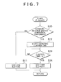
- FIG. 7 is a flowchart showing a processing flow of control for switching a B 2 pressure supply source oil passage.
- FIG. 8 is a view showing oil pressure variation resulting from the control for switching the B 2 pressure supply source oil passage.
- FIG. 1 is a view showing an overall configuration of a vehicle 1 according to this embodiment.
- the vehicle 1 includes an engine 10 , a differential unit 20 , an automatic speed change unit 30 , a differential gear unit 42 , and a drive wheel 44 .
- the vehicle 1 also includes an inverter 28 , a storage device 29 , and an ECU 60 .
- the engine 10 is an internal combustion engine constituted by a gasoline engine, a diesel engine, or the like, for example.
- the differential unit 20 is coupled to the engine 10 .
- the differential unit 20 includes a motor-generator (MG) (see FIG. 2 ) that is driven by the inverter 28 , and a power split device that distributes an output of the engine 10 between the automatic speed change unit 30 and the MG.
- MG motor-generator
- the automatic speed change unit 30 is coupled to the differential unit 20 and configured such that a speed ratio (a gear position), which is a ratio between a rotation speed of an input shaft thereof connected to the differential unit 20 and a rotation speed of an output shaft thereof connected to the differential gear unit 42 , can be modified.
- a speed ratio a gear position
- Configurations of the differential unit 20 and the automatic speed change unit 30 will be described in detail below.
- the differential gear unit 42 is coupled to the output shaft of the automatic speed change unit 30 in order to transmit power output from the automatic speed change unit 30 to the drive wheel 44 .
- the inverter 28 is electrically connected to the storage device 29 , and drives the MG provided in the differential unit 20 on the basis of a control signal from the ECU 60 .
- the storage device 29 stores power required for travel, and supplies the stored power to the inverter 28 .
- the storage device 29 is charged with power generated by the MG of the differential unit 20 and received from the inverter 28 .
- a shift sensor 2 is provided in the vehicle 1 .
- the shift sensor 2 detects a position (referred to hereafter as a “shift position (SP)”) of a shift lever 2 a operated by a user, and transmits a detection result to the ECU 60 .
- the SP includes a D (forward) position, an R (reverse) position, an N (neutral) position, a P (parking) position, and so on.
- the vehicle 1 is provided with a plurality of sensors for detecting various physical quantities required to control the vehicle 1 , such as an accelerator operation amount (an amount by which an accelerator pedal is operated by the user), a rotation speed of the engine 10 , a vehicle speed V, and so on.
- the sensors transmit detection results to the ECU 60 .
- the ECU 60 executes predetermined calculation processing on the basis of information from the respective sensors and information stored in the memory, and controls respective devices of the vehicle 1 on the basis of calculation results.
- the ECU 60 modifies a control condition (also referred to as a “shift range” hereafter) of the automatic speed change unit 30 on the basis of the SP serving as the detection result of the shift sensor 2 .
- the ECU 60 sets the shift range at a “D range (a forward range)”.
- the automatic speed change unit 30 is controlled on the basis of a shift diagram (not shown) having the accelerator operation amount, the vehicle speed, and so on, for example, as parameters so that one of a first speed gear position to a fourth speed gear position in which forward travel is possible is formed.
- the ECU 60 sets the shift range at an “R range (a reverse range)”.
- R range a reverse range
- the automatic speed change unit 30 is controlled so that a reverse gear position in which reverse travel is possible is formed.
- the ECU 60 sets the shift range at an “N range”.
- the automatic speed change unit 30 is controlled to a neutral condition (a condition in which power is not transmitted).
- the ECU 60 sets the shift range at a “P range”. In the P range, the output shaft of the automatic speed change unit 30 is fixed.
- FIG. 2 is a view showing the configurations of the differential unit 20 and the automatic speed change unit 30 shown in FIG. 1 .
- the differential unit 20 and the automatic speed change unit 30 are configured symmetrically about respective axial centers thereof, and in FIG. 2 , therefore, respective lower sides of the differential unit 20 and the automatic speed change unit 30 have been omitted.
- the differential unit 20 includes MG 1 , MG 2 , and a power split device 24 .
- the MG 1 , MG 2 are alternating current rotating electrical devices driven by the inverter 28 ( FIG. 1 ).
- the power split device 24 is constituted by a single pinion type planetary gear including a sun gear S 0 , a pinion gear P 0 , a carrier CA 0 , and a ring gear R 0 .
- the carrier CA 0 is coupled to an input shaft 22 , or in other words an output shaft of the engine 10 , in order to support the pinion gear P 0 to be capable of rotating and revolving.
- the sun gear S 0 is coupled to a rotary shaft of the MG 1 .
- the ring gear R 0 is coupled to a transmission member 26 and configured to mesh with the sun gear S 0 via the pinion gear P 0 .
- a rotary shaft of the MG 2 is coupled to the transmission member 26 . In other words, the ring gear R 0 is also coupled to the rotary shaft of the MG 2 .
- the power split device 24 When the sun gear S 0 , the carrier CA 0 , and the ring gear R 0 rotate relative to each other, the power split device 24 functions as a differential device. Respective rotation speeds of the sun gear S 0 , the carrier CA 0 , and the ring gear R 0 are related so as to be linked by a straight line on a collinear diagram, as will be described below ( FIG. 4 ).
- the differential function of the power split device 24 power output from the engine 10 is distributed between the sun gear S 0 and the ring gear R 0 .
- the MG 1 is caused to operate as a power generator by the power distributed to the sun gear S 0 , and power generated by the MG 1 is supplied to the MG 2 and stored in the storage device 29 ( FIG. 1 ).
- the automatic speed change unit 30 includes single pinion type planetary gears 32 , 34 , clutches C 1 , C 2 , brakes B 1 , B 2 , and a one-way clutch F 1 .
- the planetary gear 32 includes a sun gear S 1 , a pinion gear P 1 , a carrier CA 1 , and a ring gear R 1 .
- the planetary gear 34 includes a sun gear S 2 , a pinion gear P 2 , a carrier CA 2 , and a ring gear R 2 .
- the clutches C 1 , C 2 and the brakes B 1 , B 2 are respectively friction engagement elements operated by oil pressure.
- the respective friction engagement elements are constituted by multi-plate wet type elements in which a plurality of overlapped friction plates are pressed together by oil pressure, band brakes in which one end of a band wrapped around an outer peripheral surface of a rotating drum is tightened by oil pressure, and so on, for example.
- the one-way clutch F 1 supports the coupled carrier CA 1 and ring gear R 2 to be capable of rotating in a positive direction (a vehicle advancement direction) and incapable of rotating in a negative direction (a vehicle reverse direction).
- the differential unit 20 and the automatic speed change unit 30 are coupled by the transmission member 26 .
- An output shaft 36 coupled to the carrier CA 2 of the planetary gear 34 is coupled to the differential gear unit 42 ( FIG. 1 ).
- FIG. 3 is a view showing an engagement operation table of the automatic speed change unit 30 .
- the first speed gear position (1st) and the reverse gear position (Rev) are formed.
- identical friction engagement elements are used to form the first speed gear position in the D range and the reverse gear position in the R range.
- a friction engagement element and a solenoid valve used exclusively in the R range can be omitted, enabling a reduction in the size of the automatic speed change unit 30 .
- the vehicle 1 is switched between forward travel and reverse travel by reversing a rotation direction of the MG 2 . More specifically, the ECU 60 causes the vehicle 1 to advance in the first speed gear position by rotating the MG 2 in the positive direction while engaging the clutch C 1 and the brake B 2 , and causes the vehicle to reverse by rotating the MG 2 in the negative direction while engaging the clutch C 1 and the brake B 2 .
- FIG. 4 is a collinear diagram of a speed change mechanism constituted by the differential unit 20 and the automatic speed change unit 30 .
- a vertical line Y 1 on a collinear diagram corresponding to the differential unit 20 indicates a rotation speed of the sun gear S 0 of the power split device 24 (in other words, a rotation speed of the MG 1 ).
- a vertical line Y 2 indicates a rotation speed of the carrier CA 0 of the power split device 24 (in other words, the rotation speed of the engine 10 ).
- a vertical line Y 3 indicates a rotation speed of the ring gear R 0 of the power split device 24 (in other words, a rotation speed of the MG 2 ). Note that intervals between the vertical lines Y 1 to Y 3 are determined according to a gear ratio of the power split device 24 .
- a vertical line Y 4 on a collinear diagram corresponding to the automatic speed change unit 30 indicates a rotation speed of the sun gear S 2 of the planetary gear 34 .
- a vertical line Y 5 indicates a rotation speed of the carrier CA 2 of the planetary gear 34 and the ring gear R 1 of the planetary gear 32 , which are coupled to each other.
- a vertical line Y 6 indicates a rotation speed of the ring gear R 2 of the planetary gear 34 and the carrier CA 1 of the planetary gear 32 , which are coupled to each other.
- a vertical line Y 7 indicates a rotation speed of the sun gear S 1 of the planetary gear 32 . Intervals between the vertical lines Y 4 to Y 7 are determined according to gear ratios of the planetary gears 32 , 34 .
- the sun gear S 2 of the planetary gear 34 of the automatic speed change unit 30 is coupled to the ring gear R 0 of the differential unit 20 such that the sun gear S 2 rotates at an identical speed to the ring gear R 0 .
- the vertical line Y 4 indicating the rotation speed of the sun gear S 2 serves as a rotation speed of the input shaft of the automatic speed change unit 30 .
- the carrier CA 1 of the planetary gear 32 and the ring gear R 2 of the planetary gear 34 in the automatic speed change unit 30 are coupled to the ring gear R 0 of the differential unit 20 such that the carrier CA 1 and the ring gear R 2 rotate at an identical speed to the ring gear R 0 .
- the vertical line Y 6 indicating the rotation speed of the carrier CA 1 and the ring gear R 2 serves as the rotation speed of the input shaft of the automatic speed change unit 30 .
- the vertical line Y 5 indicating the rotation speed of the carrier CA 2 of the planetary gear 34 corresponds to an output rotation speed of the automatic speed change unit 30 (the rotation speed of the output shaft 36 ).
- the collinear diagram of the automatic speed change unit 30 takes the form of a straight line indicated by “2nd”.
- the clutch C 1 and the brake B 2 are engaged and the other clutch and brake are disengaged, as shown on the engagement operation table in FIG. 3 , the first speed gear position (1st) and the reverse gear position (Rev) are formed in accordance with the rotation condition of the MG 2 .
- the collinear diagram of the automatic speed change unit 30 takes the form of a straight line indicated by “1st”. More specifically, when the clutch C 1 is engaged, the sun gear S 2 rotates in the positive direction together with the ring gear R 0 , and when the brake B 2 is engaged, the ring gear R 2 stops rotating, with the result that the output shaft 36 of the automatic speed change unit 30 rotates in the positive direction (the forward direction).
- the collinear diagram of the automatic speed change unit 30 takes the form of a straight line indicated by “Rev”. More specifically, when the clutch C 1 is engaged, the sun gear S 2 rotates in the negative direction together with the ring gear R 0 , and when the brake B 2 is engaged, the ring gear R 2 stops rotating, with the result that the output shaft 36 of the automatic speed change unit 30 rotates in the negative direction (the reverse direction). Note that rotation of the ring gear R 2 in the negative direction is also suppressed by the one-way clutch F 1 .
- the first to fourth speed gear positions, the reverse gear position, and the neutral condition can be formed by engaging and disengaging the clutches C 1 , C 2 and the brakes B 1 , B 2 in accordance with the engagement operation table of FIG. 3 .
- continuously variable speed changing in which the rotation speed of the ring gear R 0 , or in other words a rotation speed of the transmission member 26 , can be modified continuously relative to a predetermined rotation speed of the engine 10 coupled to the carrier CA 0 , is realized by controlling the rotation of the MG 1 , MG 2 appropriately,
- the automatic speed change unit 30 is provided with a hydraulic circuit for engaging and disengaging the clutches C 1 , C 2 and the brakes B 1 , B 2 in accordance with the engagement operation table of FIG. 3 .
- FIG. 5 is a schematic view showing a configuration of a hydraulic circuit 50 that supplies oil pressure to the brake B 2 .
- the hydraulic circuit 50 includes a solenoid valve SL 2 , a manual valve MV, a switch device SC 2 , a first oil passage 51 , a second oil passage 52 , and a third oil passage 53 .
- the brake B 2 is engaged when the oil pressure (also referred to as a “B 2 pressure” hereafter) supplied thereto from the hydraulic circuit 50 equals or exceeds a predetermined pressure.
- the solenoid valve SL 2 is controlled to either an ON condition or an OFF condition on the basis of a control signal from the ECU 60 .
- the solenoid valve SL 2 When the solenoid valve SL 2 is in the ON condition, the solenoid valve SL 2 regulates a source pressure (a line pressure) supplied from an oil pressure source, not shown in the drawings, to the predetermined pressure, and outputs the predetermined pressure to the first oil passage 51 .
- a source pressure a line pressure supplied from an oil pressure source, not shown in the drawings
- the solenoid valve SL 2 When the solenoid valve SL 2 is in the OFF condition, on the other hand, the solenoid valve SL 2 regulates the source pressure to a minimum pressure MIN (zero, for example), and outputs the minimum pressure MIN to the first oil passage 51 .
- a minimum pressure MIN zero, for example
- the oil pressure (also referred to as an “SL 2 pressure” hereafter) in the first oil passage 51 is the predetermined pressure when the solenoid valve SL 2 is in the ON condition, and the minimum pressure MIN when the solenoid valve SL 2 is in the OFF condition.
- the ECU 60 controls the solenoid valve SL 2 to the ON condition when the SP is the D position. In the D range, therefore, the SL 2 pressure corresponds to the predetermined pressure.
- the manual valve MV is mechanically coupled to the shift lever 2 a in order to switch a supply destination of the source pressure (the line pressure) supplied from the oil pressure source, not shown in the drawings, in accordance with the position (the SP) of the shift lever 2 a .
- the SP is the D position
- the manual valve MV supplies the source pressure (the line pressure) to a different oil passage 54 to the second oil passage 52 .
- the SP is the R position
- the manual valve MV supplies the source pressure to the second oil passage 52 .
- the oil pressure (also referred to as an “R range pressure” hereafter) in the second oil passage 52 falls to the minimum pressure MIN when the SP is the D position, and rises to the predetermined pressure when the SP is switched to the R position.
- supply of the oil pressure to the second oil passage 52 from the oil pressure source is started in response to an operation (also referred to as a “forward-reverse switch operation” hereafter) performed by the user to switch from the D range to the R range.
- the switch device SC 2 is an ON/OFF solenoid valve that is controlled to either an ON condition or an OFF condition on the basis of a control signal from the ECU 60 .
- the switch device SC 2 is connected to the first oil passage 51 , the second oil passage 52 , and the third oil passage 53 .
- the switch device SC 2 is connected to the brake B 2 via the third oil passage 53 .
- the switch device SC 2 is configured to be capable of switching an oil passage (also referred to as a “B 2 pressure supply source oil passage” hereafter) through which the oil pressure is supplied to the brake B 2 between the first oil passage 51 and the second oil passage 52 .
- an oil passage also referred to as a “B 2 pressure supply source oil passage” hereafter
- the switch device SC 2 supplies the SL 2 pressure to the brake B 2 by setting the first oil passage 51 as the B 2 pressure supply source oil passage.
- the switch device SC 2 When the switch device SC 2 is in the OFF condition, on the other hand, the switch device SC 2 supplies the R range pressure to the brake B 2 by setting the second oil passage 52 as the B 2 pressure supply source oil passage.
- the hydraulic circuit of the automatic speed change unit 30 is configured such that when one of the solenoid valves in the hydraulic circuit breaks down (fails), the oil pressure (the SL 2 pressure) in the first oil passage 51 is supplied to the clutch C 2 in order to form the third speed gear position.
- the supply destination of the SL 2 pressure is modified from the brake B 2 to the clutch C 2 . Accordingly, the brake B 2 is disengaged and the clutch C 2 is engaged by the SL 2 pressure, whereby the third speed gear position is formed. As a result, retreat travel can be performed in the third speed gear position.
- the vehicle 1 can no longer reverse. More specifically, when the clutch C 2 is engaged, the ring gear R 0 of the differential unit 20 and the ring gear R 2 of the automatic speed change unit 30 are coupled so as to rotate integrally, but rotation of the ring gear R 2 in the reverse direction is suppressed by the one-way clutch F 1 . Hence, the ring gear R 0 (the MG 2 ) cannot rotate in the negative direction, and as a result, the vehicle 1 can no longer reverse.
- the ECU 60 engages the brake B 2 using the R range pressure by switching the B 2 pressure supply source oil passage from the SL 2 pressure to the R range pressure (in other words, by switching the switch device SC 2 from the ON condition to the OFF condition).
- the ECU 60 then reduces the SL 2 pressure from the predetermined pressure to zero (in other words, switches the solenoid valve SL 2 from the ON condition to the OFF condition). Accordingly, the clutch C 2 is not engaged during a failure even when the SL 2 pressure is supplied to the clutch C 2 , and as a result, retreat travel can be performed while reversing.
- the brake B 2 is engaged both when the first speed gear position is formed in the D range and when the reverse gear position is formed in the R range, and to enable retreat travel while reversing, the B 2 pressure supply source oil passage is switched between the D range and the R range.
- shock may be generated.
- FIG. 6 is a view (a comparative example for comparison with the invention) illustrating a principle by which shock is generated.
- the manual valve MV is operated, whereby the oil pressure (the R range pressure) in the second oil passage 52 is increased from the minimum pressure MIN to the predetermined pressure. Due to the effect of a response delay in the oil pressure, however, the R range pressure takes a small amount of time to increase to the predetermined pressure. Therefore, when the B 2 pressure supply source oil passage is switched from the first oil passage 51 to the second oil passage 52 as soon as the forward-reverse switch operation is performed, the R range pressure, which has not yet reached the predetermined pressure, is supplied to the brake B 2 .
- the B 2 pressure temporarily decreases such that the brake B 2 slips in response to a reaction force to a torque Tin input into the sun gear S 2 from the MG 2 , and as a result, the rotation speed of the ring gear R 2 of the automatic speed change unit 30 increases (see dot-dash line).
- the ECU 60 waits until the R range pressure reaches a “threshold pressure” following the forward-reverse switch operation, and then switches the B 2 pressure supply source oil passage from the first oil passage 51 to the second oil passage 52 (in other words, the ECU 60 switches the B 2 pressure supply source oil passage from the first oil passage 51 to the second oil passage 52 on condition that the oil pressure in the second oil passage 52 equals or exceeds the threshold pressure).
- the “threshold pressure” is set at an oil pressure at which the slippage amount of the brake B 2 can be sufficiently suppressed to ensure that the shock described above is not generated.
- the threshold pressure may be set at a “predetermined pressure” at which the brake B 2 is fully engaged.
- the threshold pressure may be set at a slightly smaller value than the “predetermined pressure”.
- the threshold pressure is set at an oil pressure corresponding to the predetermined pressure (either the predetermined pressure or a slightly lower oil pressure than the predetermined pressure) so that as long as the oil pressure in the second oil passage 52 equals or exceeds the “threshold pressure”, no shock is generated even when the B 2 pressure supply source oil passage is switched from the first oil passage 51 to the second oil passage 52 .
- FIG. 7 is a flowchart showing a processing flow of control performed by the ECU 60 to switch the B 2 pressure supply source oil passage. This flowchart is executed repeatedly at predetermined period intervals in the D range.
- the ECU 60 determines on the basis of the SP whether or not the forward-reverse switch operation (the operation for switching from the D range to the R range) has been performed.
- the ECU 60 keeps the switch device SC 2 in the ON condition (in other words, keeps the first oil passage 51 as the B 2 pressure supply source oil passage) and keeps the solenoid valve SL 2 in the ON condition (in other words, keeps the SL 2 pressure at the predetermined pressure) in S 11 .
- the ECU 60 starts to count (measure) an elapsed time following an execution timing of the forward-reverse switch operation in S 12 .
- the ECU 60 determines whether or not the elapsed time following the execution timing of the forward-reverse switch operation exceeds a predetermined time ⁇ . This determination corresponds to processing for determining whether or not the R range pressure has reached the threshold pressure described above on the basis of the elapsed time following the execution timing of the forward-reverse switch operation.
- the predetermined time ⁇ is set at a time required for the R range pressure to reach the threshold pressure following the execution timing of the forward-reverse switch operation.
- the predetermined time ⁇ may be a fixed value determined in advance by experiment and the like, or a variable value that is modified in accordance with parameters (an oil temperature and so on, for example) that affect a rise response of the R range pressure.
- the determination as to whether or not the R range pressure has reached the threshold pressure can be made without providing a pressure sensor to measure the R range pressure.
- the ECU 60 determines that the R range pressure has reached the threshold pressure, and switches the switch device SC 2 from the ON condition to the OFF condition. As a result, the B 2 pressure supply source oil passage is switched from the first oil passage 51 to the second oil passage 52 , whereby the R range pressure is supplied to the brake B 2 instead of the SL 2 pressure. Further, the ECU 60 switches the solenoid valve SL 2 from the ON condition to the OFF condition. As a result, the SL 2 pressure is reduced to the minimum pressure MIN.
- FIG. 8 is a view showing oil pressure variation resulting from the control for switching the B 2 pressure supply source oil passage. Note that FIG. 8 shows a case in which the threshold pressure is set at the “predetermined pressure”.
- the manual valve MV is operated in order to start supplying the source pressure from the oil pressure source to the second oil passage 52 . Accordingly, the oil pressure (the R range pressure) in the second oil passage 52 gradually increases from the minimum pressure MIN.
- the R range pressure has not yet reached the predetermined pressure (the threshold pressure), and therefore the switch device SC 2 is kept in the ON condition.
- the B 2 pressure supply source oil passage is maintained at the SL 2 pressure.
- the switch device SC 2 is switched from the ON condition to the OFF condition. Accordingly, the B 2 pressure supply source oil passage is switched from the SL 2 pressure to the R range pressure. As a result, the B 2 pressure is maintained at the predetermined pressure without decreasing.
- the solenoid valve SL 2 is switched from the ON condition to the OFF condition. Accordingly, the SL 2 pressure decreases to the minimum pressure MIN.
- the clutch C 2 is not engaged thereafter even when a failure occurs such that the SL 2 pressure is supplied to the clutch C 2 , and therefore retreat travel can be performed while reversing.
- the ECU 60 switches the B 2 pressure supply source oil passage from the first oil passage 51 to the second oil passage 52 .
- the ECU 60 switches the B 2 pressure supply source oil passage from the first oil passage 51 to the second oil passage 52 after the predetermined time ⁇ elapses from the point at which the user performs the forward-reverse switch operation (in other words, after waiting for the oil pressure in the second oil passage 52 to reach the threshold pressure) rather than at the point at which the user performs the forward-reverse switch operation (in other words, the point at which the manual valve MV is operated in order to start supplying the source pressure from the oil pressure source to the second oil passage 52 ).
- a solenoid valve that is capable of regulating the R range pressure on the basis of a control signal from the ECU 60 may be provided in place of the manual valve MV that is operated in response to an operation of the shift lever 2 a by the user, and the R range pressure may be raised in order to switch the B 2 pressure supply source oil passage from the first oil passage 51 to the second oil passage 52 as soon as the forward-reverse switch operation is performed.
- the switch device SC 2 may be configured to be capable of adjusting an output proportion of the SL 2 pressure and an output proportion of the R range pressure on the basis of a control signal from the ECU 60 so that the output proportion of the SL 2 pressure is gradually reduced in accordance with increases in the output proportion of the R range pressure.
- the invention may be applied as required to a case in which the shift range is switched from the N range to the R range.
- the invention may also be applied as required to a case in which the gear position (the speed ratio) is switched instead of the shift range.
- the solenoid valve SL 2 may be a pressure regulating valve that is capable of regulating an output oil pressure on the basis of a control signal from the ECU 60 .
- the vehicle to which the invention can be applied is not limited to the vehicle described in this embodiment.
- the invention may be applied to a typical series type or parallel type hybrid vehicle having an engine and a single MG.
- the invention may also be applied to an electric vehicle having only a MG.
Landscapes
- Engineering & Computer Science (AREA)
- General Engineering & Computer Science (AREA)
- Mechanical Engineering (AREA)
- Physics & Mathematics (AREA)
- Fluid Mechanics (AREA)
- Control Of Transmission Device (AREA)
- Hybrid Electric Vehicles (AREA)
- Electric Propulsion And Braking For Vehicles (AREA)
Abstract
Description
Claims (6)
Applications Claiming Priority (2)
| Application Number | Priority Date | Filing Date | Title |
|---|---|---|---|
| JP2014-091760 | 2014-04-25 | ||
| JP2014091760A JP6285273B2 (en) | 2014-04-25 | 2014-04-25 | Hydraulic control device for automatic transmission |
Publications (2)
| Publication Number | Publication Date |
|---|---|
| US20150308568A1 US20150308568A1 (en) | 2015-10-29 |
| US9482338B2 true US9482338B2 (en) | 2016-11-01 |
Family
ID=54261874
Family Applications (1)
| Application Number | Title | Priority Date | Filing Date |
|---|---|---|---|
| US14/682,499 Expired - Fee Related US9482338B2 (en) | 2014-04-25 | 2015-04-09 | Oil pressure control device for automatic transmission |
Country Status (4)
| Country | Link |
|---|---|
| US (1) | US9482338B2 (en) |
| JP (1) | JP6285273B2 (en) |
| CN (1) | CN105035072B (en) |
| DE (1) | DE102015105582B4 (en) |
Cited By (1)
| Publication number | Priority date | Publication date | Assignee | Title |
|---|---|---|---|---|
| US12098806B2 (en) | 2020-05-27 | 2024-09-24 | Opal Fuels, Llc | Modular and portable compressed natural gas fueling station |
Families Citing this family (3)
| Publication number | Priority date | Publication date | Assignee | Title |
|---|---|---|---|---|
| WO2018025747A1 (en) * | 2016-08-03 | 2018-02-08 | ジヤトコ株式会社 | Selection control device for automatic transmission |
| JP6853139B2 (en) * | 2017-08-08 | 2021-03-31 | トヨタ自動車株式会社 | Vehicle control device |
| JP7167549B2 (en) * | 2018-08-23 | 2022-11-09 | 株式会社デンソー | vehicle controller |
Citations (5)
| Publication number | Priority date | Publication date | Assignee | Title |
|---|---|---|---|---|
| JPH09280357A (en) | 1996-04-10 | 1997-10-28 | Fuji Heavy Ind Ltd | Line pressure control device in automatic transmission |
| JP2000205404A (en) | 1999-01-19 | 2000-07-25 | Suzuki Motor Corp | Hydraulic control device for automatic transmission |
| US6689006B2 (en) * | 2001-09-28 | 2004-02-10 | Jatco Ltd | Control device for automatic transmission |
| US8465396B2 (en) * | 2010-04-15 | 2013-06-18 | Jatco Ltd | Automatic transmission and hydraulic control method therefor |
| US20130260955A1 (en) | 2012-03-29 | 2013-10-03 | Kenta KIMATA | Control device of hybrid vehicle |
Family Cites Families (10)
| Publication number | Priority date | Publication date | Assignee | Title |
|---|---|---|---|---|
| JP4302920B2 (en) * | 2001-09-28 | 2009-07-29 | ジヤトコ株式会社 | Hydraulic control circuit for automatic transmission |
| JP2003278906A (en) * | 2002-03-25 | 2003-10-02 | Mazda Motor Corp | Oil supply control device for automatic transmission |
| JP3626151B2 (en) * | 2002-06-17 | 2005-03-02 | 日産自動車株式会社 | Hybrid transmission |
| JP4306659B2 (en) * | 2005-08-24 | 2009-08-05 | トヨタ自動車株式会社 | Hybrid vehicle drive system |
| JP2007232173A (en) * | 2006-03-03 | 2007-09-13 | Jatco Ltd | Control device for automatic transmission |
| JP4748601B2 (en) * | 2006-12-26 | 2011-08-17 | トヨタ自動車株式会社 | Hydraulic control device for automatic transmission and hybrid drive device including the same |
| WO2011099420A1 (en) * | 2010-02-10 | 2011-08-18 | 本田技研工業株式会社 | Hydraulic control device for automatic transmission |
| JP5304690B2 (en) * | 2010-03-11 | 2013-10-02 | アイシン・エィ・ダブリュ株式会社 | Hydraulic control device for automatic transmission |
| JP5527085B2 (en) * | 2010-07-28 | 2014-06-18 | トヨタ自動車株式会社 | Control device for vehicle drive device |
| JP5612624B2 (en) * | 2012-03-08 | 2014-10-22 | 富士重工業株式会社 | Range switching device |
-
2014
- 2014-04-25 JP JP2014091760A patent/JP6285273B2/en active Active
-
2015
- 2015-04-09 US US14/682,499 patent/US9482338B2/en not_active Expired - Fee Related
- 2015-04-13 DE DE102015105582.1A patent/DE102015105582B4/en not_active Expired - Fee Related
- 2015-04-24 CN CN201510202402.4A patent/CN105035072B/en not_active Expired - Fee Related
Patent Citations (6)
| Publication number | Priority date | Publication date | Assignee | Title |
|---|---|---|---|---|
| JPH09280357A (en) | 1996-04-10 | 1997-10-28 | Fuji Heavy Ind Ltd | Line pressure control device in automatic transmission |
| JP2000205404A (en) | 1999-01-19 | 2000-07-25 | Suzuki Motor Corp | Hydraulic control device for automatic transmission |
| US6689006B2 (en) * | 2001-09-28 | 2004-02-10 | Jatco Ltd | Control device for automatic transmission |
| US8465396B2 (en) * | 2010-04-15 | 2013-06-18 | Jatco Ltd | Automatic transmission and hydraulic control method therefor |
| US20130260955A1 (en) | 2012-03-29 | 2013-10-03 | Kenta KIMATA | Control device of hybrid vehicle |
| JP2013203295A (en) | 2012-03-29 | 2013-10-07 | Aisin Aw Co Ltd | Control device of hybrid vehicle |
Cited By (1)
| Publication number | Priority date | Publication date | Assignee | Title |
|---|---|---|---|---|
| US12098806B2 (en) | 2020-05-27 | 2024-09-24 | Opal Fuels, Llc | Modular and portable compressed natural gas fueling station |
Also Published As
| Publication number | Publication date |
|---|---|
| US20150308568A1 (en) | 2015-10-29 |
| CN105035072B (en) | 2019-05-03 |
| DE102015105582A1 (en) | 2015-10-29 |
| JP6285273B2 (en) | 2018-02-28 |
| JP2015209910A (en) | 2015-11-24 |
| DE102015105582B4 (en) | 2020-10-08 |
| CN105035072A (en) | 2015-11-11 |
Similar Documents
| Publication | Publication Date | Title |
|---|---|---|
| US8960034B2 (en) | Vehicle drive device | |
| US9278687B2 (en) | Control device of hybrid vehicle | |
| CN108216208B (en) | Controller for vehicle and control method for vehicle | |
| EP2578432B1 (en) | Hybrid vehicle accelerator pedal depressing force control device | |
| US9765886B2 (en) | Control system and control method for vehicle | |
| WO2013128992A1 (en) | Hybrid-drive device | |
| CN105008768B (en) | The lubrication flow control device of automatic transmission and lubrication flow control method | |
| WO2014136280A1 (en) | Vehicle hydraulic control device | |
| US9482338B2 (en) | Oil pressure control device for automatic transmission | |
| JP6337880B2 (en) | Control device for vehicle drive device | |
| WO2014170960A1 (en) | Vehicle control device and method | |
| JP2016023716A (en) | Vehicle control unit | |
| US9506559B2 (en) | Control device and control method for transmission | |
| JP4987046B2 (en) | Vehicle equipped with continuously variable transmission and control method thereof | |
| US20170203750A1 (en) | Control device for hybrid vehicle and control method of the same | |
| US10279795B2 (en) | Control device | |
| US10449952B2 (en) | Hybrid vehicle | |
| WO2014156931A1 (en) | Failure determination device for hybrid vehicles and failure determination method therefor | |
| JP2018173158A (en) | Control device of transmission | |
| JP6291170B2 (en) | Vehicle control device | |
| JP5807590B2 (en) | Control device for automatic transmission for hybrid vehicle | |
| JP4831187B2 (en) | Automatic transmission abnormality detection device | |
| JP6299281B2 (en) | Control device for vehicle drive device | |
| JP7736594B2 (en) | Transmission control device, transmission control method, and program | |
| JP6968502B2 (en) | Control device for continuously variable transmission |
Legal Events
| Date | Code | Title | Description |
|---|---|---|---|
| AS | Assignment |
Owner name: AISIN AW CO., LTD., JAPAN Free format text: ASSIGNMENT OF ASSIGNORS INTEREST;ASSIGNORS:NOHARA, HIDEHARU;SUGIMURA, TOSHIO;MATSUBARA, TOORU;AND OTHERS;REEL/FRAME:035370/0770 Effective date: 20150323 Owner name: TOYOTA JIDOSHA KABUSHIKI KAISHA, JAPAN Free format text: ASSIGNMENT OF ASSIGNORS INTEREST;ASSIGNORS:NOHARA, HIDEHARU;SUGIMURA, TOSHIO;MATSUBARA, TOORU;AND OTHERS;REEL/FRAME:035370/0770 Effective date: 20150323 |
|
| STCF | Information on status: patent grant |
Free format text: PATENTED CASE |
|
| MAFP | Maintenance fee payment |
Free format text: PAYMENT OF MAINTENANCE FEE, 4TH YEAR, LARGE ENTITY (ORIGINAL EVENT CODE: M1551); ENTITY STATUS OF PATENT OWNER: LARGE ENTITY Year of fee payment: 4 |
|
| FEPP | Fee payment procedure |
Free format text: MAINTENANCE FEE REMINDER MAILED (ORIGINAL EVENT CODE: REM.); ENTITY STATUS OF PATENT OWNER: LARGE ENTITY |
|
| LAPS | Lapse for failure to pay maintenance fees |
Free format text: PATENT EXPIRED FOR FAILURE TO PAY MAINTENANCE FEES (ORIGINAL EVENT CODE: EXP.); ENTITY STATUS OF PATENT OWNER: LARGE ENTITY |
|
| STCH | Information on status: patent discontinuation |
Free format text: PATENT EXPIRED DUE TO NONPAYMENT OF MAINTENANCE FEES UNDER 37 CFR 1.362 |
|
| FP | Lapsed due to failure to pay maintenance fee |
Effective date: 20241101 |