JP5807590B2 - Control device for automatic transmission for hybrid vehicle - Google Patents
Control device for automatic transmission for hybrid vehicle Download PDFInfo
- Publication number
- JP5807590B2 JP5807590B2 JP2012044400A JP2012044400A JP5807590B2 JP 5807590 B2 JP5807590 B2 JP 5807590B2 JP 2012044400 A JP2012044400 A JP 2012044400A JP 2012044400 A JP2012044400 A JP 2012044400A JP 5807590 B2 JP5807590 B2 JP 5807590B2
- Authority
- JP
- Japan
- Prior art keywords
- clutch
- internal combustion
- automatic transmission
- combustion engine
- friction engagement
- Prior art date
- Legal status (The legal status is an assumption and is not a legal conclusion. Google has not performed a legal analysis and makes no representation as to the accuracy of the status listed.)
- Active
Links
Images


Classifications
-
- Y—GENERAL TAGGING OF NEW TECHNOLOGICAL DEVELOPMENTS; GENERAL TAGGING OF CROSS-SECTIONAL TECHNOLOGIES SPANNING OVER SEVERAL SECTIONS OF THE IPC; TECHNICAL SUBJECTS COVERED BY FORMER USPC CROSS-REFERENCE ART COLLECTIONS [XRACs] AND DIGESTS
- Y02—TECHNOLOGIES OR APPLICATIONS FOR MITIGATION OR ADAPTATION AGAINST CLIMATE CHANGE
- Y02T—CLIMATE CHANGE MITIGATION TECHNOLOGIES RELATED TO TRANSPORTATION
- Y02T10/00—Road transport of goods or passengers
- Y02T10/60—Other road transportation technologies with climate change mitigation effect
- Y02T10/62—Hybrid vehicles
Description
本発明は、ハイブリッド車両等に搭載される自動変速機の制御装置に係り、詳しくは、内燃エンジンと自動変速機構との間に配置された第1の摩擦係合要素の係脱状態と、自動変速機構内に配置された第2の摩擦係合要素の係脱状態とを制御するハイブリッド車両用自動変速機の制御装置に関する。 The present invention relates to a control device for an automatic transmission mounted on a hybrid vehicle or the like, and more specifically, an engagement / disengagement state of a first friction engagement element disposed between an internal combustion engine and an automatic transmission mechanism, and automatic The present invention relates to a control device for an automatic transmission for a hybrid vehicle that controls an engagement / disengagement state of a second friction engagement element disposed in a transmission mechanism.
例えば、自動変速機は、内燃エンジンの出力を、トルクコンバータを介して複数の変速段を形成する自動変速機構に伝達する。また、伝達効率を良くするために、内燃エンジンと自動変速機構との間にロックアップクラッチを設け、走行状態によって内燃エンジンと自動変速機構とを直結する構成も知られている。 For example, the automatic transmission transmits the output of the internal combustion engine to an automatic transmission mechanism that forms a plurality of shift stages via a torque converter. In order to improve transmission efficiency, a configuration is also known in which a lockup clutch is provided between the internal combustion engine and the automatic transmission mechanism, and the internal combustion engine and the automatic transmission mechanism are directly connected depending on the running state.
このようなロックアップクラッチを有する構造の場合、ロックアップクラッチが何らかの理由でロック(直結)されたままとなる可能性がある。このために、ロックアップクラッチの異常を検出する手段を設けた装置が提案されている。この装置の場合、ロックアップクラッチを解放するオフの信号が出されている状態で、内燃エンジンの出力軸とロックアップクラッチの出力軸が接続される自動変速機構の入力軸との回転数の差を検出している。そして、ロックアップクラッチがオフされているにも拘らず、これら出力軸と入力軸との回転数の差が小さい場合に、ロックアップクラッチが異常であることを検出する(特許文献1参照)。 In the case of a structure having such a lockup clutch, the lockup clutch may remain locked (directly connected) for some reason. For this reason, an apparatus provided with means for detecting an abnormality of the lockup clutch has been proposed. In the case of this device, the difference in the rotational speed between the output shaft of the internal combustion engine and the input shaft of the automatic transmission mechanism to which the output shaft of the lockup clutch is connected in a state where an off signal for releasing the lockup clutch is output. Is detected. When the difference in rotational speed between the output shaft and the input shaft is small even though the lock-up clutch is turned off, it is detected that the lock-up clutch is abnormal (see Patent Document 1).
また、走行中に内燃エンジンを停止してモータによりEV走行する際に、自動変速機構の変速段が前進1〜3速段などの低速段である場合、内燃エンジンの始動に備えて発進クラッチを係合しておく装置が提案されている(特許文献2参照)。 In addition, when the internal combustion engine is stopped during traveling and EV traveling is performed by the motor, if the gear position of the automatic transmission mechanism is a low speed stage such as the first to third forward speeds, a start clutch is provided in preparation for the start of the internal combustion engine. A device for engaging is proposed (see Patent Document 2).
しかしながら、上述の特許文献2に記載されたハイブリッド車両で、走行中にロックアップクラッチがオンの状態から内燃エンジンを停止してモータで走行するEV走行を行った場合、内燃エンジンのトルク及び回転数が低下するため、内燃エンジンの出力軸と自動変速機構の入力軸との回転数の差が、ロックアップクラッチがオフであったとしても開かないことがある。このため、上述の特許文献1に記載された装置では、ロックアップクラッチの異常を検出できない場合がある。
However, in the hybrid vehicle described in
ここで、上述の特許文献2に記載の車両のように、内燃エンジンを停止した状態から内燃エンジンによる走行への切り替えを円滑に行うため、内燃エンジンを停止していても、自動変速機構内のクラッチを係合状態としておく場合がある。このような場合に、ロックアップクラッチがロックされたまま車両が停止している状態で、バッテリの充電量の低下などによりスタータモータで内燃エンジンを始動させようとすると、スタータモータの出力がロックアップクラッチ及び自動変速機構内の係合状態のクラッチを介して車輪に伝達されてしまい、運転者に違和感を与えてしまう可能性がある。
Here, as in the vehicle described in the above-mentioned
そこで本発明は、ロックアップクラッチなどの自動変速機構へ駆動力を入力する摩擦係合要素が正常であるか否かを判定できない状態で、自動変速機構へ駆動力を入力する摩擦係合要素が係合されたままスタータモータなどの始動用回転電機で内燃エンジンを始動しようとしても、始動用回転電機の出力が車輪に伝達されないような構造を提供することを目的とするものである。 Therefore, the present invention provides a friction engagement element that inputs a driving force to an automatic transmission mechanism in a state where it cannot be determined whether or not the friction engagement element that inputs a driving force to an automatic transmission mechanism such as a lockup clutch is normal. An object of the present invention is to provide a structure in which the output of the starting rotating electrical machine is not transmitted to the wheels even when the internal combustion engine is started by a starting rotating electrical machine such as a starter motor while being engaged.
本発明は(例えば図1、2、4参照)、始動用回転電機(3A)により始動する内燃エンジン(2)と前記内燃エンジンの回転を変速し得る自動変速機構(5)との間に配置される第1の摩擦係合要素(7)の係脱状態と、前記自動変速機構(5)内に配置され、且つ、前記内燃エンジン(2)停止時に電動油圧発生装置(32)により発生する油圧に基づいて係合され、係合時に前記自動変速機構(5)に入力された動力を車輪(80fl、80fr)に伝達する第2の摩擦係合要素(C−1)の係脱状態と、を制御するハイブリッド車両用自動変速機の制御装置(19)において、
前記第1の摩擦係合要素(7)が正常であることを判定する判定手段(42)と、
前記内燃エンジンの停止中であって、前記判定手段(42)が前記第1の摩擦係合要素(7)が正常であると判定していないときに、前記第1の摩擦係合要素(7)が係合された状態で前記内燃エンジンを始動する場合に前記始動用回転電機(3A)の始動トルクにより滑るように、前記第2の摩擦係合要素(C−1)の係合圧を第1の係合圧に制御する制御手段(43)と、を備え、
前記判定手段(42)は、前記第1の摩擦係合要素(7)が正常であると判定していない状態で、前記内燃エンジン(2)が始動した後に、前記内燃エンジン(2)の出力軸(8)と前記自動変速機構(5)の入力軸(10)との回転数の差を検知することにより、前記第1の摩擦係合要素(7)が正常であるか否かを判定する始動後判定を実行し、
前記制御手段(43)は、前記判定手段(42)が始動後判定で前記第1の摩擦係合要素(7)は正常でないと判定した場合に、前記第2の摩擦係合要素(C−1)を解放し、前記判定手段(42)が始動後判定で前記第1の摩擦係合要素(7)は正常であると判定した場合に、前記第2の摩擦係合要素(C−1)の係合圧を前記第1の係合圧よりも大きい第2の係合圧に制御する、ことを特徴とする。
The present invention (see, for example, FIGS. 1, 2, and 4) is arranged between an internal combustion engine (2) started by a starting rotating electrical machine (3A) and an automatic transmission mechanism (5) capable of shifting the rotation of the internal combustion engine. Generated by the electric hydraulic pressure generator (32) when the internal friction engine (2) is stopped, and is disposed in the automatic transmission mechanism (5). Engagement / disengagement state of the second friction engagement element (C-1) engaged based on hydraulic pressure and transmitting the power input to the automatic transmission mechanism (5) to the wheels (80fl, 80fr) at the time of engagement. In the control device (19) for the automatic transmission for a hybrid vehicle for controlling
Determination means (42) for determining that the first friction engagement element (7) is normal;
When the internal combustion engine is stopped and the determination means (42) does not determine that the first friction engagement element (7) is normal, the first friction engagement element (7) ) Is engaged, the engagement pressure of the second friction engagement element (C-1) is made to slide by the starting torque of the starting rotating electrical machine (3A) when the internal combustion engine is started. Control means (43) for controlling to the first engagement pressure ,
The determination means (42) outputs the output of the internal combustion engine (2) after the internal combustion engine (2) is started in a state where it is not determined that the first friction engagement element (7) is normal. It is determined whether or not the first friction engagement element (7) is normal by detecting a difference in rotational speed between the shaft (8) and the input shaft (10) of the automatic transmission mechanism (5). Perform post-start judgment
The control means (43) determines the second friction engagement element (C−) when the determination means (42) determines that the first friction engagement element (7) is not normal in the determination after starting. 1) is released, and when the determination means (42) determines that the first friction engagement element (7) is normal in the determination after starting, the second friction engagement element (C-1) ) Is controlled to a second engagement pressure larger than the first engagement pressure .
また、本発明は(例えば図1、2、4参照)、前記判定手段(42)は、前記内燃エンジン(2)が停止する前に、前記内燃エンジン(2)の出力軸(8)と前記自動変速機構(5)の入力軸(10)との回転数の差を検知することにより、前記第1の摩擦係合要素(7)が正常であることを判定する、ことを特徴とする。 Further, according to the present invention (see, for example, FIGS. 1, 2, and 4), the determination means (42) is configured so that the internal combustion engine (2) is stopped before the internal combustion engine (2) is stopped. It is characterized in that it is determined that the first friction engagement element (7) is normal by detecting a difference in rotational speed with respect to the input shaft (10) of the automatic transmission mechanism (5).
また、本発明は(例えば図1、2、4参照)、アクセル開度信号を検知するアクセル検知手段(45)を有し、
前記制御手段(43)は、前記アクセル検知手段(45)がオン信号を検知した場合には、前記判定手段(42)が前記第1の摩擦係合要素(7)が正常であると判定していなくても、前記第2の摩擦係合要素(C−1)の係合圧を前記第1の係合圧よりも大きい第3の係合圧に制御する、ことを特徴とする。
Further, the present invention (see, for example, FIGS. 1, 2, and 4) includes an accelerator detection means (45) for detecting an accelerator opening signal,
The control means (43) determines that the first friction engagement element (7) is normal when the determination means (42) is normal when the accelerator detection means (45) detects an ON signal. Even if not, the engagement pressure of the second friction engagement element (C-1) is controlled to be a third engagement pressure larger than the first engagement pressure.
なお、上記カッコ内の符号は、図面と対照するためのものであるが、これは、発明の理解を容易にするための便宜的なものであり、特許請求の範囲の構成に何等影響を及ぼすものではない。 In addition, although the code | symbol in the said parenthesis is for contrast with drawing, this is for convenience for making an understanding of invention easy, and has no influence on the structure of a claim. It is not a thing.
請求項1に係る本発明によると、判定手段が第1の摩擦係合要素が正常であると判定していないときには、制御手段は、第2の摩擦係合要素の係合圧を始動用回転電機の始動トルクにより滑る第1の係合圧に制御するため、第1の摩擦係合要素が正常であるか否かを判定できない状態で、第1の摩擦係合要素が係合されたまま始動用回転電機で内燃エンジンを始動しようとしても、始動用回転電機の出力が車輪に伝達されず、運転者に違和感を与えることを防止できる。また、内燃エンジンが始動した後に判定手段による第1の摩擦係合要素が正常であるか否かの判定を行い、正常でなければ、第2の摩擦係合要素の係合圧を小さくして、内燃エンジンへの負荷を低減でき、正常であれば、第2の摩擦係合要素の係合圧を大きくして、内燃エンジンでの走行への切り替えを円滑に行えるようにできる。 According to the first aspect of the present invention, when the determination means does not determine that the first friction engagement element is normal, the control means increases the engagement pressure of the second friction engagement element to start rotation. In order to control the first engagement pressure to be slid by the starting torque of the electric machine, the first friction engagement element remains engaged in a state where it cannot be determined whether or not the first friction engagement element is normal. Even if it is attempted to start the internal combustion engine with the starting rotating electrical machine, the output of the starting rotating electrical machine is not transmitted to the wheels, and it is possible to prevent the driver from feeling uncomfortable. Further, after the internal combustion engine is started, the determination means determines whether or not the first friction engagement element is normal. If not normal, the engagement pressure of the second friction engagement element is reduced. The load on the internal combustion engine can be reduced, and if normal, the engagement pressure of the second friction engagement element can be increased to smoothly switch to running on the internal combustion engine.
請求項2に係る本発明によると、判定手段による判定を内燃エンジンが停止する前に行うため、内燃エンジンの停止による内燃エンジンのトルク及び回転数の低下がないため、内燃エンジンの出力軸と自動変速機構の入力軸との回転数の差を検知することにより、第1の摩擦係合要素が正常であることの判定を行うことができる。 According to the second aspect of the present invention, since the determination by the determining means is performed before the internal combustion engine is stopped, there is no decrease in the torque and the rotational speed of the internal combustion engine due to the stop of the internal combustion engine. It is possible to determine that the first friction engagement element is normal by detecting the difference in the rotational speed from the input shaft of the speed change mechanism.
請求項3に係る本発明によると、運転者に車両を走行させる意思がある場合には、判定手段による判定に拘らず第2の摩擦係合要素の係合圧を大きくして、内燃エンジンによる走行を行えるようにすることができる。 According to the third aspect of the present invention, when the driver intends to drive the vehicle, the engagement pressure of the second friction engagement element is increased regardless of the determination by the determination means, and the internal combustion engine is used. It can be made to run.
以下、本発明に係る実施形態を図1乃至図9に沿って説明する。まず、図1に沿って、本実施形態の自動変速機を適用し得るハイブリッド車両の一例を説明する。 Embodiments according to the present invention will be described below with reference to FIGS. First, an example of a hybrid vehicle to which the automatic transmission of this embodiment can be applied will be described with reference to FIG.
本実施形態に係るハイブリッド車両100は、リヤモータ式ハイブリッド車両であり、前方側に内燃エンジン(E/G)2を搭載し、該内燃エンジン2と前側の左右の車輪80fl,80frとの間の伝達経路L(図2参照)上にハイブリッド車両用自動変速機(以下、単に「自動変速機」という)1が搭載された、いわゆるFF(フロントエンジン、フロントドライブ)タイプの車両のように構成されていると共に、後側の左右の車輪80rl,80rrに駆動連結されるリヤモータ(Rear Motor)(回転電機)20を備えており、つまりエンジン走行時には前輪駆動、EV走行時には後輪駆動、ハイブリッド走行時には四輪駆動が可能となるように構成されている。
A
詳細には、内燃エンジン2には、始動用回転電機であるベルト式統合型スタータ・ジェネレータ(Belt Integrated Starter Generator)3Aが接続されており、該内燃エンジン2が始動自在に構成されている。ベルト式統合型スタータ・ジェネレータ(BISG)3Aは、インバータ(Inverter)23を介して高電圧バッテリ(Hi−V Battery)24から電力が供給されることで、内燃エンジン2を高出力で始動し得ると共に、内燃エンジン2の始動中(駆動中)は、高電圧バッテリ24に対する充電も可能に構成されている。
Specifically, the
一方のスタータ(Starter)3Bは、一般的な低電圧バッテリ(Lo−V Battery)26(いわゆる12V型電源)で駆動するようなスタータである。本ハイブリッド車両100では、常温(例えば0度以上)ではベルト式統合型スタータ・ジェネレータ(BISG)3Aを用いてアイドル回転数よりも高い回転数まで内燃エンジン2の回転数を上昇した後に該内燃エンジン2の点火を行い、低温時(例えば0度未満)ではスタータ3Bを用いて内燃エンジン2の通常始動を行う。
One starter (Starter) 3B is a starter that is driven by a general low-voltage battery (Lo-V Battery) 26 (so-called 12V type power supply). In this
上記内燃エンジン2には、詳しくは後述する自動変速機1が接続されている。自動変速機1は、大まかに、トルクコンバータ(T/C)4、後述の内燃エンジン2の回転を変速し得る自動変速機構(T/M)5、油圧制御装置(V/B)6などを有して構成されており、内燃エンジン2にはトルクコンバータ4が駆動連結されている。該トルクコンバータ4には自動変速機構(T/M)5が駆動連結されており、該自動変速機構5は、詳しくは後述するように、ディファレンシャル装置D(図2参照)を介して左右車軸81l,81rに接続され、前側の左右の車輪80fl,80frに駆動連結されている。なお、トルクコンバータ4の後述するポンプインペラ4a(図2参照)には、機械式オイルポンプが駆動連結されている。
The
また、該自動変速機構5には、後述の摩擦係合要素(クラッチやブレーキ)を油圧制御するための油圧制御装置(V/B)6が付設されており、該油圧制御装置6は、自動変速機の制御装置である制御部(TCU:Transmission Control Unit)19からの電子指令に基づき、内蔵されたソレノイドバルブ等が電子制御される。また、油圧制御装置6には、詳しくは後述するように、内燃エンジン2とは独立して駆動される電動油圧発生装置である電動オイルポンプ32が付設されており、該電動オイルポンプ32から油圧制御装置6に対して油圧供給し得るように構成されている。
The
なお、電動オイルポンプ32や制御部19は、低電圧バッテリ26の電力を用いて駆動される。該低電圧バッテリ26は、DC/DCコンバータ(降圧回路)25を介して高電圧バッテリ24に接続されており、該高電圧バッテリ24から電力が供給されるように構成されている。
The
一方、上記リヤモータ20は、インバータ23を介して高電圧バッテリ24に接続されており、力行・回生自在に構成されている。該リヤモータ20は、モータ切離しクラッチC−Mを介してギヤボックス(Gear Box)21に駆動連結されている。ギヤボックス21には、図示を省略した所定減速比の減速ギヤ機構及びディファレンシャル装置が内蔵されており、モータ切離しクラッチC−Mの係合時には、該リヤモータ20の回転を、ギヤボックス21の減速ギヤ機構で減速しつつ、かつディファレンシャル装置で左右車軸82l,82rの差回転を吸収しつつ、後側の左右の車輪80rl,80rrに伝達する。
On the other hand, the
続いて、自動変速機1の構成について図2に沿って説明する。本自動変速機1は、内燃エンジン2(図1参照)と前側の左右の車輪80fl,80frとの間の伝達経路Lを構成するように配置されており、内燃エンジン2(図1参照)のクランク軸に接続し得る自動変速機の入力軸8を有していると共に、該入力軸8の軸方向を中心として上述のトルクコンバータ4と自動変速機構5とを備えている。
Next, the configuration of the
トルクコンバータ4は、自動変速機1の入力軸8に接続されたポンプインペラ4aと、作動流体を介して該ポンプインペラ4aの回転が伝達されるタービンランナ4bと、タービンランナ4bからポンプインペラ4aに戻るオイルを整流しつつトルク増大作用を生じさせるステータ4cとを有していると共に、該タービンランナ4bは、上記入力軸8と同軸上に配設された上記自動変速機構5の入力軸10に接続されている。また、該トルクコンバータ4には、第1の摩擦係合要素であるロックアップクラッチ7が備えられており、該ロックアップクラッチ7が係合されると、上記自動変速機1の入力軸8の回転が自動変速機構5の入力軸10に直接伝達される。即ち、ロックアップクラッチ7は、内燃エンジン2と自動変速機構5との間に配置され、係合状態で内燃エンジン2と自動変速機構5とを直結する。
The torque converter 4 includes a pump impeller 4a connected to the
なお、ステータ4cは、ワンウェイクラッチFによって、ポンプインペラ4aの回転よりタービンランナ4bの回転が下回る状態で回転が固定されて、オイルの流れの反力を受圧してトルク増大作用を生じさせ、タービンランナ4bの回転が上回る状態になると空転して、オイルの流れが負方向に作用しないように構成されている。
The
また、ポンプインペラ4aは、その自動変速機構5側の端部が、図2では図示を省略した機械式オイルポンプ31に駆動連結されており、つまり機械式オイルポンプ31は、入力軸8を介して内燃エンジン2に連動されるように駆動連結されている。
Further, the pump impeller 4 a is driven and connected at its end on the
上記自動変速機構5には、入力軸10上において、プラネタリギヤSPと、プラネタリギヤユニットPUとが備えられている。上記プラネタリギヤSPは、サンギヤS1、キャリヤCR1、及びリングギヤR1を備えており、該キャリヤCR1に、サンギヤS1及びリングギヤR1に噛合するピニオンP1を有している、いわゆるシングルピニオンプラネタリギヤである。
The
また、該プラネタリギヤユニットPUは、4つの回転要素としてサンギヤS2、サンギヤS3、キャリヤCR2、及びリングギヤR2を有し、該キャリヤCR2に、サンギヤS2及びリングギヤR2に噛合するロングピニオンPLと、サンギヤS3に噛合するショートピニオンPSとを互いに噛合する形で有している、いわゆるラビニヨ型プラネタリギヤである。 The planetary gear unit PU has a sun gear S2, a sun gear S3, a carrier CR2, and a ring gear R2 as four rotating elements. The carrier CR2 has a long pinion PL that meshes with the sun gear S2 and the ring gear R2, and the sun gear S3. This is a so-called Ravigneaux type planetary gear that has meshing short pinions PS that mesh with each other.
上記プラネタリギヤSPのサンギヤS1は、ミッションケース9に一体的に固定されているボス部に接続されて回転が固定されている。また、上記リングギヤR1は、上記入力軸10の回転と同回転(以下「入力回転」という。)になっている。更に上記キャリヤCR1は、該固定されたサンギヤS1と該入力回転するリングギヤR1とにより、入力回転が減速された減速回転になると共に、第2の摩擦係合要素であるクラッチC−1及びクラッチC−3に接続されている。
The sun gear S <b> 1 of the planetary gear SP is connected to a boss portion that is integrally fixed to the
上記プラネタリギヤユニットPUのサンギヤS2は、バンドブレーキからなるブレーキB−1に接続されてミッションケースに対して固定自在となっていると共に、上記クラッチC−3に接続され、該クラッチC−3を介して上記キャリヤCR1の減速回転が入力自在となっている。また、上記サンギヤS3は、クラッチC−1に接続されており、上記キャリヤCR1の減速回転が入力自在となっている。 The sun gear S2 of the planetary gear unit PU is connected to a brake B-1 formed of a band brake so as to be freely fixed to the transmission case, and is connected to the clutch C-3 via the clutch C-3. Thus, the decelerated rotation of the carrier CR1 can be input. The sun gear S3 is connected to the clutch C-1, so that the decelerated rotation of the carrier CR1 can be input.
更に、上記キャリヤCR2は、入力軸10の回転が入力されるクラッチC−2に接続され、該クラッチC−2を介して入力回転が入力自在となっており、また、ワンウェイクラッチF−1及びブレーキB−2に接続されて、該ワンウェイクラッチF−1を介してミッションケースに対して一方向の回転が規制されると共に、該ブレーキB−2を介して回転が固定自在となっている。そして、上記リングギヤR2は、カウンタギヤ11に接続されており、該カウンタギヤ11は、カウンタシャフト15、ディファレンシャル装置Dを介して車輪80fl,80frに接続されている。
Further, the carrier CR2 is connected to a clutch C-2 to which the rotation of the
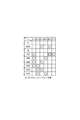
以上のように構成されたハイブリッド車両100は、内燃エンジン2の駆動力を用いたエンジン走行にあっては、図1に示すモータ切離しクラッチC−Mが解放されて、リヤモータ20が車輪80rl,80rrから切離された状態にされる。そして、自動変速機1において、車速やアクセル開度に応じて制御部19により最適な変速段が判断されることで油圧制御装置6が電子制御され、その変速判断に基づき形成される前進1速段〜前進6速段及び後進段で内燃エンジン2の駆動力を変速して、車輪80fl,80frに該内燃エンジン2の駆動力を伝達する。なお、自動変速機1の前進1速段〜前進6速段及び後進段は、図3に示す作動表のように、各クラッチC−1〜C−3、ブレーキB−1〜B−2、ワンウェイクラッチF−1が作動することにより達成される。
In the
上記エンジン走行からハイブリッド走行に移行する際は、図1に示すモータ切離しクラッチC−Mが係合されて、リヤモータ20が車輪80rl,80rrに駆動連結される。これにより、上記エンジン走行に加え、アクセル開度(運転者の駆動力要求)に基づき、リヤモータ20の駆動力が適宜にアシスト或いは回生され、つまり内燃エンジン2の駆動力とリヤモータ20の駆動力とを用いてハイブリッド車両100が走行される。
When shifting from the engine running to the hybrid running, the motor disconnection clutch CM shown in FIG. 1 is engaged, and the
なお、上記内燃エンジン2の駆動力によるエンジン走行時の加速時などにあっては、モータ切離しクラッチC−Mを解放し、リヤモータ20を車輪80rl,80rrから切離して走行抵抗にならないようにしてもよい。また、エンジン走行時であっても、減速時にはモータ切離しクラッチC−Mを係合し、リヤモータ20で回生ブレーキを実行する方が燃費向上に対して好ましい。
During acceleration of the engine running by the driving force of the
そして、EV走行にあっては、図1に示すモータ切離しクラッチC−Mが係合されて、リヤモータ20が車輪80rl,80rrに駆動連結され、かつ内燃エンジン2が停止されると共に自動変速機1における各クラッチC−2〜C−3、ブレーキB−1〜B−2が解放されて、該自動変速機1が空転可能状態にされる。これにより、アクセル開度(運転者の駆動力要求)に基づき、リヤモータ20の駆動力が適宜に力行或いは回生され、つまりリヤモータ20の駆動力だけを用いてハイブリッド車両100が走行される。
In EV traveling, the motor disconnection clutch CM shown in FIG. 1 is engaged, the
なお、このEV走行中にあっては、自動変速機構5の車輪80fl,80frに駆動連結された部材(例えばディファレンシャル装置D,カウンタシャフト15、カウンタギヤ11、プラネタリギヤユニットPUの各ギヤなど)が連れ回されると共に、内燃エンジン2の停止によって機械式オイルポンプが停止される。従って、内燃エンジン停止時には電動オイルポンプ32によって、自動変速機構5の潤滑部位への潤滑油の供給を行う必要がある。
During the EV traveling, members (for example, the differential device D, the
また、EV走行中にあっては、EV走行からハイブリッド走行への移行準備として、自動変速機構内のクラッチC−1を係合状態にしておく。EV走行中にクラッチC−1を係合したとしても、自動変速機構5は、牽引状態であってエンジンブレーキ時と同様な状態であり、上記ワンウェイクラッチF−1が空転するため、空転可能状態に制御されていることになる。このようにクラッチC−1を係合状態にしておくための油圧も、電動オイルポンプ32によって発生しておく必要がある。
Further, during EV travel, as a preparation for transition from EV travel to hybrid travel, the clutch C-1 in the automatic transmission mechanism is in an engaged state. Even if the clutch C-1 is engaged during EV traveling, the
また、本実施形態の場合、ロックアップクラッチ7が正常であるか否かを検出するために、内燃エンジン2の回転数(エンジン回転)と自動変速機構5の入力軸10の回転数(インプット回転)とをそれぞれ検出するようにしている。このために、内燃エンジン2の出力軸の回転数を検知するエンジン回転数センサ40と、自動変速機構5の入力軸10の回転数を検知する入力軸回転数センサ41とを備える。図示の例の場合、エンジン回転数センサ40は、内燃エンジン2の出力軸に直結される自動変速機1の入力軸8に配置しているが、内燃エンジン2の出力軸に配置しても良い。また、入力軸回転数センサ41は、入力軸10に直結されて同じ速度で回転する部分に配置すれば良く、図示の例では、他の部材との干渉を考慮して、クラッチC−2近傍の外周側に配置している。
Further, in the present embodiment, in order to detect whether or not the lock-up clutch 7 is normal, the rotational speed of the internal combustion engine 2 (engine rotation) and the rotational speed of the
本実施形態の場合、自動変速機の制御装置である制御部19は、図4に示すように、上述のエンジン回転数センサ40と入力軸回転数センサ41との信号に基づいて、ロックアップクラッチ7が正常であるか否かを判定する判定手段42を有する。判定手段42は、後述するロックアップ制御手段44がロックアップクラッチ7の係合解除の信号を出した状態で、エンジン回転数センサ40により検出したエンジン回転数と、入力軸回転数センサ41により検出した自動変速機構の入力軸10の回転数との差が、所定値よりも大きい場合に、ロックアップクラッチ7が正常である判定し、所定値以下の場合に、ロックアップクラッチ7が正常でないと判定する。
In the case of the present embodiment, as shown in FIG. 4, the
例えば、内燃エンジン2の始動時に自動変速機1の入力軸8にエンジントルクが入力されると、ロックアップクラッチ7の係合が解除されていれば、このトルクがトルクコンバータ4を介して自動変速機構5の入力軸10に入力される。このとき、トルクがトルクコンバータ4を介して入力されるため、自動変速機1の入力軸8と自動変速機構5の入力軸10との間で、回転数の差が生じる。一方、ロックアップクラッチ7の係合が解除されていなければ、エンジントルクがロックアップクラッチ7を介して自動変速機構5の入力軸10に入力されることになる。このため、自動変速機1の入力軸8と自動変速機構5の入力軸10との間で、回転数の差がほとんど生じない。したがって、この回転数の差からロックアップクラッチ7が正常であるか否かを判定できる。
For example, when the engine torque is input to the
このような制御部19は、判定手段42の他に、クラッチC−1の係合圧を制御する制御手段であり、クラッチC−1の係脱状態を制御するクラッチ制御手段43、ロックアップクラッチ7の係脱状態を制御するロックアップ制御手段44、アクセルのオン信号を検知するアクセル検知手段45などを有する。なお、制御部19は、これら以外の各種制御手段を備え、油圧制御装置6及びロックアップクラッチ7を制御する。
The
油圧制御装置6には、各クラッチC−1〜C−3、ブレーキB−1〜B−2の油圧サーボに対して供給する係合圧を制御する複数のリニアソレノイドバルブ等が備えられており、特に油圧制御装置6には、クラッチC−1の油圧サーボ46に対して供給する係合圧PC1を、例えばライン圧PLを元圧として調圧出力自在なリニアソレノイドバルブSLC1と、ロックアップクラッチ7の係合圧PL−UP(トルクコンバータ4の内圧)を、例えばセカンダリ圧PSECを元圧として調圧出力自在なリニアソレノイドバルブSLUと、が備えられている。そして、該リニアソレノイドバルブSLC1はクラッチ制御手段43により、該リニアソレノイドバルブSLUはロックアップ制御手段44により、それぞれ制御され得るように構成されている。
The
クラッチ制御手段43は、変速制御マップや運転者のシフト操作などに基づいて、クラッチC−1の係脱を行わせるように、リニアソレノイドバルブSLC1を制御する。また、上述したように、EV走行中にあっては、EV走行からハイブリッド走行への移行準備として、クラッチC−1を係合させるように、リニアソレノイドバルブSLC1を制御する。更に、後述するように、判定手段42の判定に応じて、或いは、判定していない場合、更にはアクセル検知手段45の検知結果のそれぞれに応じて、クラッチC−1の係合圧を制御するようにリニアソレノイドバルブSLC1を制御する。 The clutch control means 43 controls the linear solenoid valve SLC1 so that the clutch C-1 is engaged / disengaged based on a shift control map, a driver's shift operation, and the like. Further, as described above, during EV traveling, the linear solenoid valve SLC1 is controlled so that the clutch C-1 is engaged as preparation for transition from EV traveling to hybrid traveling. Further, as will be described later, the engagement pressure of the clutch C-1 is controlled in accordance with the determination by the determination means 42, or in the case where the determination is not made, and further in accordance with each detection result of the accelerator detection means 45. The linear solenoid valve SLC1 is controlled as described above.
ロックアップ制御手段44は、ロックアップ制御マップなどに基づいて、ロックアップクラッチ7の係脱を行わせるように、リニアソレノイドバルブSLUを制御する。EV走行中は、通常、ロックアップクラッチ7の係合は解除されている。 The lockup control means 44 controls the linear solenoid valve SLU so that the lockup clutch 7 is engaged and disengaged based on a lockup control map or the like. During EV travel, the lockup clutch 7 is normally disengaged.
アクセル検知手段45は、アクセルのオン・オフ(更にはアクセル開度)を検知するアクセルセンサ47の信号を検知する。言い換えれば、アクセル検知手段45は、運転者の車両を走行させる意思を検知する。
The accelerator detection means 45 detects a signal of an
ここで、例えばリニアソレノイドバルブSLUの異常などにより、ロックアップ制御手段44がロックアップクラッチ7を解除する信号を出していても、ロックアップクラッチ7の係合が解除されていない、即ち、ロック状態のままとなる正常でない(異常)状態が生じる場合がある。そして、この状態でEV走行をしていると、エンジントルクが無いため、ロックアップクラッチ7が正常であるか否かを判定するのに十分なエンジン回転数と自動変速機構の入力軸10の回転数との差が生じないため、上述のようにロックアップクラッチ7が正常であるか否かの判定ができない。また、EV走行している場合には、上述したように、クラッチC−1を係合状態としている。
Here, even if the lockup control means 44 issues a signal for releasing the lockup clutch 7 due to, for example, an abnormality of the linear solenoid valve SLU, the engagement of the lockup clutch 7 is not released, that is, the locked state. An unhealthy (abnormal) condition may remain that remains. When the vehicle is running in EV in this state, there is no engine torque, so the engine speed sufficient to determine whether the lockup clutch 7 is normal and the rotation of the
このように、ロックアップクラッチ7が正常であるか否かを判定できないまま、EV走行状態で車両が停止し、ロックアップクラッチ7が異常であるとする。尚、この場合はエンジンが停止しており機械式オイルポンプ31からの油圧がなく、また電動オイルポンプ32からの油圧ではロックアップクラッチ7をオンに維持できないため、ロックアップクラッチの係合は解除されている。この状態で、クラッチC−1が係合したままであると、バッテリ充電量が低下して、ベルト式統合型スタータ・ジェネレータ(BISG)3Aにより内燃エンジン2を始動させようとした場合に、始動に際して機械式オイルポンプ31が駆動されて油圧を発生させることでロックアップクラッチ7が係合(ロック状態)されてしまい、このBISG3Aの始動トルクがロックアップクラッチ7及びクラッチC−1を介して車輪に伝達されてしまう。特に、BISG3Aの始動トルクは大きいため、運転者には、ブレーキを踏んで車両を停止させているにも拘らず車両が発進しようとする始動トルクが伝わってしまい、違和感が生じる可能性がある。
As described above, it is assumed that the vehicle stops in the EV traveling state without determining whether the lock-up clutch 7 is normal, and the lock-up clutch 7 is abnormal. In this case, since the engine is stopped and there is no hydraulic pressure from the
そこで、本実施形態では、制御部19は、次のように、クラッチC−1の係合圧を制御するようにしている。即ち、判定手段42がロックアップクラッチ7が正常であると判定していないときに、ロックアップクラッチ7が係合された状態で、クラッチC−1がBISG3Aの少なくとも始動トルクにより滑るように、クラッチ制御手段43がクラッチC−1の係合圧を第1の係合圧に制御する。
Therefore, in the present embodiment, the
具体的には、クラッチC−1の係合圧を、EV走行からハイブリッド走行への移行準備として制御される圧力(通常はライン圧)よりも低くし、ロックアップクラッチ7が係合された状態で、クラッチC−1がBISG3Aの始動トルクにより滑るようにする。なお、スタータ3Bでエンジンを始動する場合があるが、スタータ3Bの始動トルクは、BISG3Aの始動トルクよりも小さいため、クラッチC−1で伝達されても、運転者に与える違和感は少ない。勿論、第1の係合圧をスタータ3Bの始動トルクで滑るように制御しても良い。
Specifically, the engagement pressure of the clutch C-1 is made lower than the pressure (usually the line pressure) controlled as preparation for transition from EV traveling to hybrid traveling, and the lockup clutch 7 is engaged. Then, the clutch C-1 is made to slide by the starting torque of the
但し、第1の係合圧は、クラッチC−1がエンジン始動後のクリープトルクを伝達するように制御されることが好ましい。このクリープトルクとは、ロックアップクラッチ7が解放されている状態で、内燃エンジン2のアイドリングトルクがトルクコンバータ4で増幅され、自動変速機構5に入力されたトルクである。即ち、第1の係合圧は、車両の停止状態で、ロックアップクラッチ7が正常である場合にトルクコンバータ4を介して伝達される内燃エンジン2のアイドリングトルク(クリープトルク)は保持するが、ロックアップクラッチ7がロックされていた場合に伝達されるスタータ3B或いはBISG3Aの始動トルクでは滑るように制御される。
However, the first engagement pressure is preferably controlled so that the clutch C-1 transmits the creep torque after the engine is started. The creep torque is torque that is input to the
なお、本実施形態では、第1の係合圧を、エンジン最大クリープトルクを保持できるように制御している。例えば、冷温時などに内燃エンジン2のアイドリング回転数が上がって、通常よりもクリープトルクが大きくなる場合がある。このため、第1の係合圧として、その内燃エンジン2のアイドリング回転数が最大となる場合のクリープトルク(エンジン最大クリープトルク)を保持できるようにしている。
In the present embodiment, the first engagement pressure is controlled so that the engine maximum creep torque can be maintained. For example, the idling speed of the
次に、判定手段42は、ロックアップクラッチ7が正常であると判定していない状態で内燃エンジン2が始動した後に、ロックアップクラッチ7が正常であるか否かを判定する始動後判定を実行する。即ち、内燃エンジン2が始動した後は、エンジン回転数センサ40と入力軸回転数センサ41との検知結果により、判定手段42による判定が可能となる。そして、判定手段42が始動後判定でロックアップクラッチ7は正常でないと判定した場合には、クラッチ制御手段43が、クラッチC−1を解放する。これにより、ロックアップクラッチ7が異常でロックされたままであっても、エンジン出力が車輪まで伝達されることを防止する。
Next, the determination means 42 performs a post-start determination that determines whether or not the lockup clutch 7 is normal after the
これに対して、判定手段42が始動後判定でロックアップクラッチ7は正常であると判定した場合には、クラッチ制御手段43が、クラッチC−1の係合圧を上述の第1の係合圧よりも大きい第2の係合圧に制御する。具体的には、EV走行からハイブリッド走行への移行準備として制御される圧力に戻す。この場合には、ロックアップクラッチ7の係合が解除されているため、クラッチC−1が係合されていても、エンジン出力がトルクコンバータ4を介して車輪まで伝達されることになり、運転者が車両を走行させる場合に、円滑に、ハイブリッド走行が可能となる。
On the other hand, when the
一方、アクセル検知手段45が、アクセルがオンである、即ち、運転者が車両を発進させようとしていることを検知した場合には、クラッチ制御手段43が、判定手段42がロックアップクラッチ7が正常であると判定していなくても、クラッチC−1の係合圧を上述の第1の係合圧よりも大きい第3の係合圧に制御する。この第3の係合圧は、上述の第2の係合圧と同じとする。但し、ロックアップクラッチ7がロックされたままの状態であることを考慮して、第2の係合圧よりも低くし、ロックアップクラッチ7がロックされていた場合の発進時のショックを和らげるようにしても良い。
On the other hand, when the
このような本実施形態の制御について、図5ないし図8を用いてより具体的に説明する。なお、図5ないし図8で、横軸が時間軸、車速は車両の速度(実線)、クラッチ圧はクラッチC−1の係合圧(破線)、エンジン回転は内燃エンジン2の回転数(一点鎖線)、インプット回転は自動変速機構5の入力軸10の回転数(二点鎖線)である。
Such control according to the present embodiment will be described more specifically with reference to FIGS. 5 to 8, the horizontal axis is the time axis, the vehicle speed is the vehicle speed (solid line), the clutch pressure is the engagement pressure of the clutch C-1 (broken line), and the engine speed is the rotational speed of the internal combustion engine 2 (one point). The chain rotation) and the input rotation are the rotation speed (two-dot chain line) of the
まず、本実施形態では、判定手段42によるロックアップクラッチ7の正常であるか否かの判定は、内燃エンジン2が停止する前に行う。そして、図5に示すように、内燃エンジン2が停止する前に判定手段42によりロックアップクラッチ7が正常であるか否かを判定できた場合、ロックアップクラッチ7が異常であるとの判定結果であれば、図5(A)に示すように、車両が停止する直前にクラッチC−1を解放する。これにより、その後、内燃エンジン2が再始動しても、エンジン出力が車輪に伝達することを防止する。
First, in the present embodiment, the
一方、ロックアップクラッチ7が正常であるとの判定結果であれば、図5(B)に示すように、クラッチC−1の係合圧を維持したまま、EV走行からハイブリッド走行への移行準備として制御される圧力とする。 On the other hand, if the determination result indicates that the lock-up clutch 7 is normal, as shown in FIG. 5B, preparation for transition from EV traveling to hybrid traveling is performed while maintaining the engagement pressure of the clutch C-1. The pressure is controlled as follows.
これに対して、内燃エンジン2が停止する前に判定手段42によりロックアップクラッチ7が正常であるか否かを判定できなかった場合、クラッチC−1の係合圧を維持したままとすると、図6に示すように、エンジン再始動によりエンジン回転が上昇して、ブレーキを踏んで車両を停止させているにも拘らず車両が発進しようとする始動トルクが伝わってしまい、違和感が生じる可能性がある。
On the other hand, if the determination means 42 cannot determine whether the lock-up clutch 7 is normal before the
したがって、本実施形態では、図7に示すように、判定手段42がロックアップクラッチ7が正常であるか否かを判定できなかった場合、クラッチC−1の係合圧を上述した第1の係合圧に制御する。これにより、ロックアップクラッチ7が異常であっても、図7(A)に示すように、エンジン再始動によりクラッチC−1が滑り、BISG3Aの始動トルクにより違和感が生じることを防止できる。そして、内燃エンジン2が始動して、判定手段42による判定が可能となったら、再度、判定手段42による始動後判定を行い、ロックアップクラッチ7が異常であると判定し、クラッチC−1を解放する。
Therefore, in this embodiment, as shown in FIG. 7, when the determination means 42 cannot determine whether or not the lockup clutch 7 is normal, the engagement pressure of the clutch C-1 is set to the first level described above. Control to engagement pressure. Thereby, even if the lock-up clutch 7 is abnormal, as shown in FIG. 7A, it is possible to prevent the clutch C-1 from slipping due to the engine restart and causing a sense of incongruity due to the starting torque of the
一方、ロックアップクラッチ7が正常である場合、図7(B)に示すように、エンジンが再始動しても、ロックアップクラッチ7が解除されているため、クラッチC−1の係合状態に拘らず、車輪に急激にトルクが伝達されることはない。但し、この状態では、トルクコンバータ4を介してクリープトルクが自動変速機構5に入力される。第1の係合圧は、上述したようにクリープトルクは保持するため、運転者がブレーキを解除すれば、車両はこのクリープトルクで発進しようとする。図7(B)ではブレーキがかかっている状態なので、車速はゼロである。
On the other hand, when the lock-up clutch 7 is normal, as shown in FIG. 7B, the lock-up clutch 7 is released even when the engine is restarted. Regardless, no torque is suddenly transmitted to the wheels. However, in this state, creep torque is input to the
そして、内燃エンジン2が始動して、判定手段42による判定が可能となったら、再度、判定手段42による始動後判定を行い、ロックアップクラッチ7が正常であると判定し、クラッチC−1の係合圧をEV走行からハイブリッド走行への移行準備として制御される第2の係合圧に制御する。即ち、通常の係合圧に戻す。
Then, when the
更に、判定手段42がロックアップクラッチ7が正常であるか否かを判定できなかった場合でも、運転者に発進の意思があれば、図8に示すように、クラッチC−1の係合圧を、一度、第1の係合圧に低下させた後、アクセルのオン信号の検知により、再度、第3の係合圧に上昇させる。これにより、ロックアップクラッチ7が異常である場合には、図8(A)に示すように、エンジン始動時には、クラッチC−1が滑るが、アクセルがオンとなった場合に、クラッチC−1の係合圧が上昇し、車両が前進する。また、ロックアップクラッチ7が正常である場合には、図8(B)に示すように、エンジン始動時には、クラッチC−1の係合圧は低いが、アクセルがオンとなった場合に、クラッチC−1の係合圧が上昇し、車両が前進する。 Further, even if the determination means 42 cannot determine whether or not the lock-up clutch 7 is normal, if the driver intends to start, as shown in FIG. Is once lowered to the first engagement pressure and then raised again to the third engagement pressure by detecting the accelerator on signal. As a result, when the lock-up clutch 7 is abnormal, as shown in FIG. 8A, the clutch C-1 slips when the engine starts, but when the accelerator is turned on, the clutch C-1 The engagement pressure rises and the vehicle moves forward. Further, when the lock-up clutch 7 is normal, as shown in FIG. 8 (B), when the engine is started, the engagement pressure of the clutch C-1 is low, but the clutch is turned on when the accelerator is turned on. The engagement pressure of C-1 rises and the vehicle moves forward.
このような本実施形態の制御の1例について、図4を参照しつつ、図9を用いて説明する。制御が開始されると、内燃エンジン2の運転時に判定手段42がロックアップクラッチ7が正常であるか否かの判定を行い、異常であれば(S1)、フェールセーフでクラッチC−1を解放する(S2)。次に、判定手段42が異常ではなく、正常であると判定すれば(S3)、EV走行時にクラッチC−1の係合を第1の係合圧に低下させる制御は行わない(S4)。
One example of the control of this embodiment will be described with reference to FIG. 4 and FIG. When the control is started, the determination means 42 determines whether or not the lockup clutch 7 is normal when the
これに対して、判定手段42が、S1で異常の判定ができず、且つ、S3で正常の判定もできなかった場合、まず、制御部19は、例えばエンジン回転数センサ40の信号から内燃エンジン2が停止しているか否か判断し(S5)、停止していれば、車速センサ48(図4)から車速がゼロ、即ち、車両が停止状態であるか否かを判断する(S6)。そして、制御部19は、車両が停止していれば、アクセル検知手段45によりアクセルオフを検知し(S7)、アクセルオフであれば、クラッチ制御手段34がクラッチC−1の係合圧を第1の係合圧に制御する(S8)。
On the other hand, when the
次に、内燃エンジン2が再始動すると(S9)、制御部19は、アクセル検知手段45によりアクセルオンを検知すれば(S10)、クラッチ制御手段34がクラッチC−1の係合圧を第1の係合圧から通常の係合圧(第2の係合圧)に戻す(S11)。一方、アクセルオフの状態で、エンジン始動後に判定手段42がロックアップクラッチ7が正常であると判定すれば(S12)、クラッチ制御手段34がクラッチC−1の係合圧を第1の係合圧から通常の係合圧(第2の係合圧)に戻す(S11)。
Next, when the
これに対して、アクセルオフの状態で、エンジン始動後に判定手段42がロックアップクラッチ7が異常であると判定すれば(S13)、フェールセーフでクラッチC−1を解放する(S14)。一方、S12で正常であるとの判定ができず、S13で異常であるとの判定もできなかった場合、S10に戻り、クラッチC−1の係合圧を第1の係合圧としたまま、S10以降のステップを実行する。 On the other hand, if the determination means 42 determines that the lockup clutch 7 is abnormal after the engine is started in the accelerator-off state (S13), the clutch C-1 is released in a fail-safe manner (S14). On the other hand, if it is not possible to determine that it is normal in S12 and it is not possible to determine that it is abnormal in S13, the process returns to S10, and the engagement pressure of the clutch C-1 is kept at the first engagement pressure. , S10 and subsequent steps are executed.
このように構成される本実施形態の場合、ロックアップクラッチ7が正常であるか否かを判定できない状態であっても、クラッチC−1の係合圧をBISG3Aの始動トルクで滑る第1の係合圧に制御するため、ロックアップクラッチ7が係合されたままBISG3Aで内燃エンジン2を始動しようとしても、BISG3Aの出力が車輪に伝達されず、運転者に違和感を与えることを防止できる。一方、第1の係合圧は、クリープトルクは伝達するため、ロックアップクラッチ7が正常であった場合には、車輪にクリープトルクを伝達できる。
In the case of this embodiment configured as described above, even if it is not possible to determine whether or not the lock-up clutch 7 is normal, the first slipping of the engagement pressure of the clutch C-1 with the starting torque of the
また、本実施形態では、判定手段42による判定を内燃エンジン2が停止する前に行うため、内燃エンジン2の出力軸と自動変速機構5の入力軸との回転数の差を検知することにより、ロックアップクラッチ7が正常であることの判定を行える。
In the present embodiment, since the determination by the determination means 42 is performed before the
また、内燃エンジン2が始動した後に判定手段42によるロックアップクラッチ7が正常であるか否かの判定を行い、正常でなければ(異常であれば)、クラッチC−1の係合圧を小さくして、内燃エンジン2への負荷を低減でき、正常であれば、クラッチC−1の係合圧を大きくして、EV走行から内燃エンジン2での走行への切り替えを円滑に行えるようにできる。
Further, after the
また、運転者に車両を走行させる意思がある場合、即ち、アクセル検知手段45がアクセルオンを検知した場合には、判定手段42による判定に拘らずクラッチC−1の係合圧を大きくして、内燃エンジン2による走行を行えるようにできる。言い換えれば、ロックアップクラッチ7がロックされたままで、エンジントルクがクラッチC−1を介して車輪に急激に伝達されるとしても、運転者に車両を走行させる意思があれば、それほど違和感を与えない。また、運転者に車両を走行させる意思がある場合にもクラッチC−1の係合圧を低下させると、例えば、ロックアップクラッチ7の修理のために整備工場まで自走できなくなる。したがって、本実施形態では、ロックアップクラッチ7が異常であっても、運転者に車両を走行させる意思があれば、クラッチC−1の係合圧を低下させる制御を実行しないようにしている。
Further, when the driver intends to drive the vehicle, that is, when the
なお、上述の実施形態では、前輪を内燃エンジン2により、後輪をリヤモータ20により駆動するハイブリッド車両に本発明を適用した場合について説明したが、エンジンとモータ及び自動変速機構とを係脱するクラッチを有し、このクラッチの係脱によりEV走行とハイブリッド走行とを切り換える構造にも、本発明を適用可能である。この場合、このクラッチが第1の摩擦係合要素となる。
In the above-described embodiment, the case where the present invention is applied to the hybrid vehicle in which the front wheels are driven by the
また、本実施形態では、自動変速機1が前進6速段及び後進段を達成する多段式自動変速機であるものを説明したが、これに限らず、例えば前進7速段以上や前進5速段以下の多段変速機、或いはベルト式、トロイダル式、リングコーン式の無段変速する無段変速機であっても、本発明を適用し得る。
In the present embodiment, the
また、本実施形態では、EV走行中に自動変速機構5内のクラッチC−1を係合状態としておくもの、即ち、第2の摩擦係合要素をクラッチC−1としたが、走行状況や車種によっては、この第2の摩擦係合要素は、自動変速機構5内のその他のクラッチやブレーキとしても良い。例えば、車両を後進させるリバースのときには、第2の摩擦係合要素をクラッチC−3とし、このクラッチC−3の係合圧を、上述したクラッチC−1と同様に制御する。
In the present embodiment, the clutch C-1 in the
1 ハイブリッド車両用自動変速機
2 内燃エンジン
3A ベルト式統合型スタータ・ジェネレータ(BISG、始動用回転電機)
3B スタータ(始動用回転電機)
4 トルクコンバータ
5 自動変速機構
7 ロックアップクラッチ(第1の摩擦係合要素)
19 制御部(自動変速機の制御装置)
20 リヤモータ(回転電機)
32 電動オイルポンプ(電動油圧発生装置)
40 エンジン回転数センサ
41 入力軸回転数センサ
42 判定手段
43 クラッチ制御手段(制御手段)
44 ロックアップ制御手段
45 アクセル検知手段
47 アクセルセンサ
80fl,80fr 車輪
100 車両
C−1 クラッチ(第2の摩擦係合要素)
DESCRIPTION OF
3B Starter (starting rotating electrical machine)
4
19 Control unit (automatic transmission control device)
20 Rear motor (rotary electric machine)
32 Electric oil pump (electric oil pressure generator)
40
44 Lock-up control means 45 Accelerator detecting means 47 Accelerator sensor 80fl,
Claims (3)
前記第1の摩擦係合要素が正常であることを判定する判定手段と、
前記内燃エンジンの停止中であって、前記判定手段が前記第1の摩擦係合要素が正常であると判定していないときに、前記第1の摩擦係合要素が係合された状態で前記内燃エンジンを始動する場合に前記始動用回転電機の始動トルクにより滑るように、前記第2の摩擦係合要素の係合圧を第1の係合圧に制御する制御手段と、を備え、
前記判定手段は、前記第1の摩擦係合要素が正常であると判定していない状態で、前記内燃エンジンが始動した後に、前記内燃エンジンの出力軸と前記自動変速機構の入力軸との回転数の差を検知することにより、前記第1の摩擦係合要素が正常であるか否かを判定する始動後判定を実行し、
前記制御手段は、前記判定手段が始動後判定で前記第1の摩擦係合要素は正常でないと判定した場合に、前記第2の摩擦係合要素を解放し、前記判定手段が始動後判定で前記第1の摩擦係合要素は正常であると判定した場合に、前記第2の摩擦係合要素の係合圧を前記第1の係合圧よりも大きい第2の係合圧に制御する、
ことを特徴とするハイブリッド車両用自動変速機の制御装置。 An engagement / disengagement state of a first friction engagement element disposed between an internal combustion engine started by a starting rotating electrical machine and an automatic transmission mechanism capable of shifting the rotation of the internal combustion engine, and disposed in the automatic transmission mechanism. And engaging / disengaging a second friction engagement element that is engaged based on the hydraulic pressure generated by the electric hydraulic pressure generator when the internal combustion engine is stopped, and that transmits the power input to the automatic transmission mechanism to the wheel when engaged. In a control device for an automatic transmission for a hybrid vehicle that controls the state,
Determining means for determining that the first friction engagement element is normal;
When the internal combustion engine is stopped and the determination means does not determine that the first friction engagement element is normal, the first friction engagement element is engaged with the first friction engagement element. Control means for controlling the engagement pressure of the second friction engagement element to the first engagement pressure so as to slide by the starting torque of the starting rotating electrical machine when starting the internal combustion engine ,
The determination means rotates the output shaft of the internal combustion engine and the input shaft of the automatic transmission mechanism after the internal combustion engine is started in a state where it is not determined that the first friction engagement element is normal. Performing a post-startup determination to determine whether the first friction engagement element is normal by detecting a difference in number;
The control means releases the second friction engagement element when the determination means determines that the first friction engagement element is not normal in the determination after start-up, and the determination means determines the determination after the start-up. When it is determined that the first friction engagement element is normal, the engagement pressure of the second friction engagement element is controlled to be a second engagement pressure that is larger than the first engagement pressure. ,
A control device for an automatic transmission for a hybrid vehicle.
ことを特徴とする、請求項1に記載のハイブリッド車両用自動変速機の制御装置。 The determination means detects the difference in rotational speed between the output shaft of the internal combustion engine and the input shaft of the automatic transmission mechanism before the internal combustion engine stops, so that the first friction engagement element is normal. Is determined,
The control device for an automatic transmission for a hybrid vehicle according to claim 1, characterized in that:
前記制御手段は、前記アクセル検知手段がオン信号を検知した場合には、前記判定手段が前記第1の摩擦係合要素が正常であると判定していなくても、前記第2の摩擦係合要素の係合圧を前記第1の係合圧よりも大きい第3の係合圧に制御する、
ことを特徴とする、請求項1又は2に記載のハイブリッド車両用自動変速機の制御装置。 Accelerator detecting means for detecting the accelerator opening signal,
When the accelerator detecting means detects an ON signal, the control means does not determine that the first friction engagement element is normal, but the second friction engagement is not detected. Controlling the engagement pressure of the element to a third engagement pressure larger than the first engagement pressure;
The control apparatus for an automatic transmission for a hybrid vehicle according to claim 1 or 2, wherein
Priority Applications (1)
| Application Number | Priority Date | Filing Date | Title |
|---|---|---|---|
| JP2012044400A JP5807590B2 (en) | 2012-02-29 | 2012-02-29 | Control device for automatic transmission for hybrid vehicle |
Applications Claiming Priority (1)
| Application Number | Priority Date | Filing Date | Title |
|---|---|---|---|
| JP2012044400A JP5807590B2 (en) | 2012-02-29 | 2012-02-29 | Control device for automatic transmission for hybrid vehicle |
Publications (3)
| Publication Number | Publication Date |
|---|---|
| JP2013180611A JP2013180611A (en) | 2013-09-12 |
| JP2013180611A5 JP2013180611A5 (en) | 2014-04-24 |
| JP5807590B2 true JP5807590B2 (en) | 2015-11-10 |
Family
ID=49271599
Family Applications (1)
| Application Number | Title | Priority Date | Filing Date |
|---|---|---|---|
| JP2012044400A Active JP5807590B2 (en) | 2012-02-29 | 2012-02-29 | Control device for automatic transmission for hybrid vehicle |
Country Status (1)
| Country | Link |
|---|---|
| JP (1) | JP5807590B2 (en) |
Families Citing this family (2)
| Publication number | Priority date | Publication date | Assignee | Title |
|---|---|---|---|---|
| WO2015129571A1 (en) * | 2014-02-28 | 2015-09-03 | アイシン・エィ・ダブリュ株式会社 | Vehicle control device |
| JPWO2015129811A1 (en) * | 2014-02-28 | 2017-03-30 | アイシン・エィ・ダブリュ株式会社 | VEHICLE CONTROL DEVICE AND TRANSMISSION CONTROL DEVICE |
Family Cites Families (5)
| Publication number | Priority date | Publication date | Assignee | Title |
|---|---|---|---|---|
| JP3948147B2 (en) * | 1999-02-03 | 2007-07-25 | マツダ株式会社 | Hybrid vehicle |
| JP4054966B2 (en) * | 2002-03-29 | 2008-03-05 | アイシン・エィ・ダブリュ株式会社 | Control device for automatic transmission |
| JP4462170B2 (en) * | 2005-11-07 | 2010-05-12 | 日産自動車株式会社 | Engine start control device for hybrid vehicle |
| JP2010155590A (en) * | 2009-01-05 | 2010-07-15 | Nissan Motor Co Ltd | Start control device for hybrid car |
| JP5229572B2 (en) * | 2009-03-25 | 2013-07-03 | アイシン・エィ・ダブリュ株式会社 | Vehicle control device and vehicle drive system |
-
2012
- 2012-02-29 JP JP2012044400A patent/JP5807590B2/en active Active
Also Published As
| Publication number | Publication date |
|---|---|
| JP2013180611A (en) | 2013-09-12 |
Similar Documents
| Publication | Publication Date | Title |
|---|---|---|
| JP5799873B2 (en) | Control device for hybrid vehicle | |
| JP3915698B2 (en) | Control device for hybrid vehicle | |
| US9643608B2 (en) | Vehicular power transmission device | |
| JP3921850B2 (en) | Oil pump drive control device | |
| JP5839110B2 (en) | Control device for automatic transmission for hybrid vehicle | |
| JP2007309486A (en) | Starting control device of vehicle | |
| JP2008265533A (en) | Drive control device of hybrid vehicle | |
| US9592832B2 (en) | Extending hybrid electric vehicle regenerative braking | |
| JP5958094B2 (en) | Control device for vehicle drive device | |
| JPH09286245A (en) | Hydraulic control device for hybrid vehicle | |
| JP5862803B2 (en) | Transmission control apparatus and control method | |
| JP2013203140A (en) | Control device for automatic transmission for hybrid vehicle | |
| JP5282758B2 (en) | Charge control system | |
| JP3977787B2 (en) | Hydraulic control device for hybrid vehicle | |
| JP5807590B2 (en) | Control device for automatic transmission for hybrid vehicle | |
| JP6465204B2 (en) | Control device for vehicle drive device | |
| JP6007832B2 (en) | Automatic transmission and control device corresponding to open failure of hydraulic control valve in automatic transmission | |
| JP2011236992A (en) | Control device of vehicle driving system | |
| JP6237438B2 (en) | Vehicle neutral control device | |
| JP2000166023A (en) | Controller of motor generator for hybrid vehicle | |
| JP2009264481A (en) | Control device for vehicle drive mechanism | |
| JP2000055186A (en) | Engine starting device | |
| JP4054966B2 (en) | Control device for automatic transmission | |
| JP2001165305A (en) | Deceleration control equipment for vehicle | |
| JP3671692B2 (en) | Automatic engine stop and restart control device for vehicle |
Legal Events
| Date | Code | Title | Description |
|---|---|---|---|
| A521 | Written amendment |
Free format text: JAPANESE INTERMEDIATE CODE: A523 Effective date: 20140306 |
|
| A621 | Written request for application examination |
Free format text: JAPANESE INTERMEDIATE CODE: A621 Effective date: 20140306 |
|
| A977 | Report on retrieval |
Free format text: JAPANESE INTERMEDIATE CODE: A971007 Effective date: 20150410 |
|
| A131 | Notification of reasons for refusal |
Free format text: JAPANESE INTERMEDIATE CODE: A131 Effective date: 20150421 |
|
| A521 | Written amendment |
Free format text: JAPANESE INTERMEDIATE CODE: A523 Effective date: 20150616 |
|
| TRDD | Decision of grant or rejection written | ||
| A01 | Written decision to grant a patent or to grant a registration (utility model) |
Free format text: JAPANESE INTERMEDIATE CODE: A01 Effective date: 20150811 |
|
| A61 | First payment of annual fees (during grant procedure) |
Free format text: JAPANESE INTERMEDIATE CODE: A61 Effective date: 20150824 |
|
| R150 | Certificate of patent or registration of utility model |
Ref document number: 5807590 Country of ref document: JP Free format text: JAPANESE INTERMEDIATE CODE: R150 |