US9481096B2 - Robotic arm - Google Patents

Robotic arm Download PDF

Info

Publication number
US9481096B2
US9481096B2 US14/728,765 US201514728765A US9481096B2 US 9481096 B2 US9481096 B2 US 9481096B2 US 201514728765 A US201514728765 A US 201514728765A US 9481096 B2 US9481096 B2 US 9481096B2
Authority
US
United States
Prior art keywords
joint
motor
module
robotic arm
link
Prior art date
Legal status (The legal status is an assumption and is not a legal conclusion. Google has not performed a legal analysis and makes no representation as to the accuracy of the status listed.)
Active
Application number
US14/728,765
Other versions
US20150290817A1 (en
Inventor
Andrew A. Goldenberg
Brent Bailey
Matthew GRYNIEWSKI
Xiaojia He
Yi Yang
Current Assignee (The listed assignees may be inaccurate. Google has not performed a legal analysis and makes no representation or warranty as to the accuracy of the list.)
China Superrobotics Ltd
Original Assignee
Engineering Services Inc
Priority date (The priority date is an assumption and is not a legal conclusion. Google has not performed a legal analysis and makes no representation as to the accuracy of the date listed.)
Filing date
Publication date
Application filed by Engineering Services Inc filed Critical Engineering Services Inc
Priority to US14/728,765 priority Critical patent/US9481096B2/en
Assigned to ENGINEERING SERVICES INC. reassignment ENGINEERING SERVICES INC. ASSIGNMENT OF ASSIGNORS INTEREST (SEE DOCUMENT FOR DETAILS). Assignors: BAILEY, BRENT, YANG, YI, GOLDENBERG, ANDREW A., GRYNIEWSKI, MATTHEW, HE, XIAOJIA
Publication of US20150290817A1 publication Critical patent/US20150290817A1/en
Application granted granted Critical
Publication of US9481096B2 publication Critical patent/US9481096B2/en
Assigned to ENGINEERING SERVICES INC. reassignment ENGINEERING SERVICES INC. CHANGE OF ADDRESS Assignors: ENGINEERING SERVICES INC.
Assigned to CHINA SUPERROBOTICS LIMITED reassignment CHINA SUPERROBOTICS LIMITED ASSIGNMENT OF ASSIGNORS INTEREST (SEE DOCUMENT FOR DETAILS). Assignors: ENGINEERING SERVICES INC.
Assigned to CHINA SUPERROBOTICS LIMITED reassignment CHINA SUPERROBOTICS LIMITED CORRECTIVE ASSIGNMENT TO CORRECT THE LIST OF ASSIGNED PROPERTIES PREVIOUSLY RECORDED AT REEL: 051382 FRAME: 0708. ASSIGNOR(S) HEREBY CONFIRMS THE ASSIGNMENT . Assignors: ENGINEERING SERVICES INC.
Active legal-status Critical Current
Anticipated expiration legal-status Critical

Links

Images

Classifications

    • BPERFORMING OPERATIONS; TRANSPORTING
    • B25HAND TOOLS; PORTABLE POWER-DRIVEN TOOLS; MANIPULATORS
    • B25JMANIPULATORS; CHAMBERS PROVIDED WITH MANIPULATION DEVICES
    • B25J18/00Arms
    • B25J18/02Arms extensible
    • BPERFORMING OPERATIONS; TRANSPORTING
    • B25HAND TOOLS; PORTABLE POWER-DRIVEN TOOLS; MANIPULATORS
    • B25JMANIPULATORS; CHAMBERS PROVIDED WITH MANIPULATION DEVICES
    • B25J17/00Joints
    • BPERFORMING OPERATIONS; TRANSPORTING
    • B25HAND TOOLS; PORTABLE POWER-DRIVEN TOOLS; MANIPULATORS
    • B25JMANIPULATORS; CHAMBERS PROVIDED WITH MANIPULATION DEVICES
    • B25J19/00Accessories fitted to manipulators, e.g. for monitoring, for viewing; Safety devices combined with or specially adapted for use in connection with manipulators
    • B25J19/0025Means for supplying energy to the end effector
    • B25J19/0029Means for supplying energy to the end effector arranged within the different robot elements
    • BPERFORMING OPERATIONS; TRANSPORTING
    • B25HAND TOOLS; PORTABLE POWER-DRIVEN TOOLS; MANIPULATORS
    • B25JMANIPULATORS; CHAMBERS PROVIDED WITH MANIPULATION DEVICES
    • B25J9/00Programme-controlled manipulators
    • B25J9/08Programme-controlled manipulators characterised by modular constructions
    • YGENERAL TAGGING OF NEW TECHNOLOGICAL DEVELOPMENTS; GENERAL TAGGING OF CROSS-SECTIONAL TECHNOLOGIES SPANNING OVER SEVERAL SECTIONS OF THE IPC; TECHNICAL SUBJECTS COVERED BY FORMER USPC CROSS-REFERENCE ART COLLECTIONS [XRACs] AND DIGESTS
    • Y10TECHNICAL SUBJECTS COVERED BY FORMER USPC
    • Y10STECHNICAL SUBJECTS COVERED BY FORMER USPC CROSS-REFERENCE ART COLLECTIONS [XRACs] AND DIGESTS
    • Y10S901/00Robots
    • Y10S901/19Drive system for arm
    • Y10S901/23Electric motor
    • YGENERAL TAGGING OF NEW TECHNOLOGICAL DEVELOPMENTS; GENERAL TAGGING OF CROSS-SECTIONAL TECHNOLOGIES SPANNING OVER SEVERAL SECTIONS OF THE IPC; TECHNICAL SUBJECTS COVERED BY FORMER USPC CROSS-REFERENCE ART COLLECTIONS [XRACs] AND DIGESTS
    • Y10TECHNICAL SUBJECTS COVERED BY FORMER USPC
    • Y10TTECHNICAL SUBJECTS COVERED BY FORMER US CLASSIFICATION
    • Y10T74/00Machine element or mechanism
    • Y10T74/20Control lever and linkage systems
    • Y10T74/20207Multiple controlling elements for single controlled element
    • Y10T74/20305Robotic arm
    • Y10T74/20317Robotic arm including electric motor

Definitions

  • This disclosure relates to robotic arms and in particular robotic arms with internal cables.
  • Robot joints used in robotic arms are well known. However, when joints and arms are to be used in certain applications constraints are introduced in the specifications that are not generally present in general applications. For example the payload to weight ratio is very important in space and planetary applications and mobile robot applications. As well, size constraints may be very important in manufacturing and mobile robot applications. Any design of modern robot needs to consider: low weight, high payload, long reach, kinematic dexterity, high accuracy and repeatability, and low cost.
  • a combination two joint module may provide advantages in regard to a compact size, low weight, high payload, and high accuracy and repeatability. Such joints are particularly useful in robotic arms. As well, modular robotic arms having internal cables are advantageous over conventional robotic arms.
  • a two joint module includes a module housing, a first joint and a second joint.
  • the module housing has a structural support portion.
  • the first joint has a first motor and a first motor axis and a first joint axis.
  • the second joint has a second motor and a second motor axis and a second joint axis.
  • the second joint axis is at an angle to the first joint axis.
  • the first joint is attached to the structural support portion and the second joint is attached to the structural support portion.
  • the first joint may be a pitch joint.
  • the second joint may be one of a roll joint and a yaw joint.
  • the second joint may be a prismatic joint.
  • the second motor may be perpendicular to the second joint axis.
  • the first motor axis and the first axis may be parallel.
  • Each joint may include a gearhead and a drive operably attached to the respective motor.
  • the drive may be a harmonic drive.
  • Each motor may include absolute encoders and incremental encoders. Each motor may be capable of measuring speed and current.
  • the two joint module may include torque sensors. Each joint of the two joint module may be a low power, high torque joint.
  • One of the first and second motor may be include angled gearing such the second joint axis is at an angle to the first joint axis.
  • the first joint axis may be orthogonal or at right angles to the second joint axis.
  • the right angle gearing may be one of a worm gear and a hypoid gear.
  • the module housing may act as an electromagnetic shield.
  • the module housing may include a module housing box and each motor may be external to the module housing box.
  • the module housing may include motor housing.
  • the first joint and second joint may be configured to be reversible.
  • Each motor may be operably connected to cables that are internal to the module housing.
  • One of the first joint and second joint may have an active side and a passive side of the housing and the other of the first joint and second joint may have a hollow central axis and the cables may pass through the passive side of the housing of one joint and the hollow central axis of the other joint.
  • a two joint module includes a module housing, a first joint and a second joint.
  • the first joint has a passive side and an active side and has a first motor.
  • the second joint has a hollow central axis and an off axis drive and has a second motor.
  • Internal cabling runs through the passive side of the first joint and through the hollow central axis of the second joint.
  • Each joint may include electronics and the electronics are capable of being connected in series and the cables are operably connected to the electronics and operably connected to the motors.
  • the first motor and gearhead may be a combination motor and gearhead.
  • the harmonic drive may be internal to the combination motor and gearhead.
  • a robotic arm includes a first link and a first joint.
  • the first link has internal link cables extending from one end to an opposed end thereof.
  • the first joint is operably connected to the first link at one end thereof.
  • the first joint has a hollow drive shaft, an off axis drive and a first joint motor and first joint internal cables extending through the hollow drive shaft. The link cables and the first joint cables are operably connected.
  • the robotic arm may further include a second joint operably connected to the first link.
  • the second joint module has an active side, a passive side with electronic connectors, second joint internal cables, and a second joint motor and the active side is mechanically connected to the link and the electronic connectors of the passive side are operably connected to the link cables.
  • the robotic arm may further include a second link operably connected to one of the first joint and the second joint.
  • the first joint and the second joint may be a combination two joint module.
  • the robotic arm may further including a third joint and a fourth joint each operably connected to the second link.
  • the third joint and the fourth joint may be a combination two joint module.
  • the robotic arm may further include a fifth joint and a sixth joint.
  • the fifth joint and the sixth joint may be a combination two joint module.
  • FIG. 1 is a perspective view of an embodiment of a two joint module which may be used as a wrist joint;
  • FIG. 2 is a blown apart view of the two joint module of FIG. 2
  • FIG. 3 is cross sectional view of the two joint module of FIG. 2 taken along line 3 - 3
  • FIG. 4 is a cross sectional view of the two joint module of FIG. 2 taken along line 4 - 4 ;
  • FIG. 5 is a perspective view of an alternate embodiment of a two joint module which may be used as an elbow joint;
  • FIG. 6 is perspective view of an alternate embodiment of a two joint module which may be used as a shoulder joint
  • FIG. 7 perspective view of an alternate embodiment of a two joint module similar to that show in FIG. 6 but also including a fork connector;
  • FIG. 8 is a perspective view of an arm assembly including the two degree of freedom joins shown in FIGS. 1, 5 and 7 ;
  • FIG. 9 is a perspective view of an alternate embodiment of a two joint module
  • FIG. 10 is a top view of the two joint module of FIG. 9 ;
  • FIG. 11 is a side view of the two joint module of FIG. 9 ;
  • FIG. 12 is a front view of the two joint module of FIG. 9 ;
  • FIG. 13 is a blown apart view of the two joint module of FIG. 9 ;
  • FIG. 14 is a cross sectional view of the two joint module of FIG. 9 ;
  • FIG. 15 is a blown apart view of a two joint module which includes a roll joint and a prismatic joint;
  • FIG. 16 is a perspective view of an arm including the two joint modules of FIGS. 9 and 15 ;
  • FIG. 17 is a perspective blown apart view of the arm of FIG. 16 .
  • Module 10 includes a first joint 12 , a second joint 14 and a module housing 16 .
  • the first joint 12 has a first joint axis 28 and the second joint 14 has a second joint axis 46 and the first axis 28 is generally orthogonal to the second axis 46 .
  • the angle between the two joints need not be orthogonal rather it could be at another angle depending on the design constraints.
  • the first joint is a pitch joint and the second joint is a roll joint or yaw joint.
  • the first joint 12 includes a first motor 18 , a first gearhead 20 and a first drive 22 .
  • the first drive 22 is a harmonic drive.
  • the first motor 20 and first gearhead 18 may be incorporated in the same unit 24 as shown herein.
  • the first motor and gearhead may also include an incremental encoder 21 .
  • the motor gearhead is a speed reducer to reduce the power required to operate the first module.
  • the gearhead has a reduction ratio of 20584:1.
  • the use of the gearhead provides for the option to use smaller, lighter and lower power motors.
  • the incremental encoder 21 measures relative rotational position of the motor and in turn by determining the rate of change of the rotational position the speed of the motor is determined. The position of the motor is determined prior to the gearhead.
  • the first drive 22 may include an integrated torque sensor 23 which measures the output torque that is applied after all of the gearing.
  • the first joint also includes an absolute encoder 26 which determines the rotational position of the output after all of the gears. The absolute encoder is used to determine the relative rotational position of the outer link with respect to the inner link.
  • the first joint 12 has a first motor axis and a first joint axis 28 .
  • the first motor 20 , first gearhead 18 , first drive 22 and first absolute encoder 26 are concentric with the first joint axis 28 .
  • the second joint 14 includes a second motor 32 , a second gearhead 30 and a second drive 34 .
  • the second motor or drive 34 may be a harmonic drive.
  • the second motor 32 and second gearhead 30 may be incorporated in the same unit 36 as shown herein.
  • the second motor and gearhead may also include an incremental encoder 31 .
  • the incremental encoder 31 measures relative rotational position of the motor and from the rate of change of the relative rotational position the speed of the motor is determined. The position of the motor is determined prior to the gearhead.
  • the second drive 34 may include an integrated torque sensor 35 which measures the output torque that is applied after all of the gearing.
  • the second joint also includes an absolute encoder 38 which determines the rotational position of the output after all of the gears. The absolute encoder is used to determine the rotational position of the link.
  • the second joint 14 includes a hollow drive shaft 40 and angled gearing that allows for internal cabling 41 .
  • a worm gear 42 and worm 44 connect the second motor and gearhead combination 36 to the drive shaft 40 .
  • the angle may be perpendicular but it will be appreciated by those skilled in the art that the different angles may be chosen depending on the design constraints for the joint.
  • the positioning of the motor and gearhead combination 36 in this fashion allows for a compact two joint module.
  • the second joint 14 has a second joint axis 46 .
  • the second drive 34 , second absolute encoder 38 and hollow drive shaft 40 are concentric with the second axis 46 .
  • the second drive 34 may be a harmonic drive.
  • the second drive or motor 34 , second motor axis and gearhead combination 36 are perpendicular to second joint axis 46 .
  • the second motor axis of the second motor and gearhead combination 36 is parallel to the first motor axis of the first motor and gearhead combination 24 .
  • Electronic modules 48 are operably connected to each of the first joint 12 and the second joint 14 .
  • the electronic modules 48 are operably connected to a control unit (not shown).
  • the electronic modules 48 receive information from the control unit in regard to the desired movement of the joint and control the first motor 18 and second motor 30 accordingly.
  • Each electronic module 48 includes a torque sensor amplifier to increase strength of the output signal from the torque sensors.
  • Each electronic module 48 includes interfaces for all of the sensors such as the incremental encoders, absolute encoder, and output from torque sensor amplifier, and is capable of digitizing all sensor information.
  • Each electronic module 48 includes power connections.
  • the module housing 16 includes a first housing cover with electronic connections 53 .
  • a first output plate 50 is operably attached to the output of the first drive 22 .
  • the output plate 50 is adapted for mechanical external connections and is movable relative to the module housing 16 and output plate 50 is the active side of the housing.
  • the first housing cover 52 with electronic connections 53 is for the joint modules interfaces for power and communications and is used for positioning the link which is attached to the module 10 and first housing cover is the passive side of the housing.
  • the second joint 14 has a combined second output plate 54 and electronic connections 55 .
  • the active first output plate 50 , passive first housing cover with electronic connections 53 and the second output plate, together with the hollow drive shaft 40 of the second joint 14 allows for internal cabling.
  • the module housing 16 also includes a housing box 56 .
  • the module housing box 56 is robust enough to transmit forces and torques and the module housing box is a structural support portion and first joint 12 and second joint 14 are attached thereto.
  • the module housing 16 enclosures the electronics and motors and protects them from external environment.
  • the module housing 16 acts as an electromagnetic shield.
  • the module housing 16 is made from metal and is conductive.
  • the electronics modules 48 are enclosed by the housing 16 .
  • the housing 16 provides electromagnetic shielding.
  • FIGS. 1 to 4 show a small relative to the other joints shown in arm 70 in FIG. 8 and joint module 10 may be used as a wrist module.
  • FIG. 5 shows a medium sized embodiment of a two joint module 60 which is similar to that shown in FIGS. 1 to 4 but is somewhat larger and may be used as an elbow module. Since the elbow joint 60 has a greater distance from the payload, the elbow joint 60 is required to generate greater torques and thus requires larger motors and drives.
  • FIG. 6 show a larger sized embodiment of a two joint module 62 that is similar to modules 10 and 60 but larger and may be used as a shoulder module.
  • FIG. 7 is a larger module similar to that shown in FIG. 6 but further including a fork connector 64 .
  • Joint module 62 includes larger motors and drives than those of modules 10 and 60 and can generate higher torques.
  • the electronics are configured so that the joint described herein with internal cabling are capable of being connected in series.
  • MOTOR POWER JOINT (W) GEAR RATIO TORQUE Module 62 Shoulder First Joint 50 35652:1 826 Shoulder Second 25 39243:1 367 Joint Module 60 Elbow First Joint 25 37226:1 334 Elbow Second Joint 5 23085:1 71 Module 10 Wrist First Joint 5 20584:1 65 Wrist Second Joint 5 21309:1 42
  • joints are typically used in conjunctions with links to form a robot arm.
  • the configuration of each robot arm can vary greatly depending on the design specifications which typically include such things as reach, weight of payload to weight of arm, operational environment, dexterity, human machine interfaces, accuracy and repeatability, and control methods.
  • An example of an arm which uses the joint modules of FIGS. 1 to 7 is shown in FIG. 8 .
  • Arm 70 includes two joint module 10 as the wrist, two joint module 60 as the elbow and two joint module 62 with fork connector 64 as the shoulder.
  • the modules are connected with links 72 .
  • one advantage of these joints is that there is no external cabling. This is advantageous as it reduces the risk of the cabling getting caught on some unknown projection. Note that in the embodiments shown in FIGS. 1 to 8 the joints have internal cabling.
  • the housing 16 provides electromagnetic shielding the cables can be lighter and more bendable since the cables do not need to include shielding or shielded connectors.
  • the modules can be used with links 72 to form a multi degrees of freedom robotic arm 70 .
  • One embodiment of the arm 70 has six degrees of freedom and a reach of 2250 mm.
  • the arm has a mass of 38 kg and a payload capacity of 20 kg.
  • the arm consists of a fork connector 64 , shoulder module 62 , lower link 72 , elbow module 60 , upper link 72 and a wrist module 10 .
  • Module 80 includes a first joint 82 , a second joint 84 and a module housing 86 .
  • the first joint 82 includes a first motor 88 , a first gearhead 90 and a first drive 92 .
  • the first drive may be a harmonic drive.
  • the first motor 88 and first gearhead 90 may be incorporated in the same unit 94 as shown herein.
  • the first motor and gearhead may also include an incremental encoder 91 .
  • the incremental encoder 91 measures relative rotational position of the motor and from the rate of change of the relative rotational position the speed of the motor is determined. The position of the motor is determined prior to the gearhead.
  • the first joint also includes an absolute encoder 96 which determines the rotational position of the output after all of the gears. The absolute encoder is used to determine the position of the link.
  • the first joint 82 has a first joint axis 98 .
  • the first motor 88 , first gearhead 90 , first incremental encoder 91 , first drive 92 and first absolute encoder 96 are concentric with the first axis 98 .
  • the first motor 88 has a first motor axis.
  • the second joint 84 includes a second motor 100 , a second gearhead 102 , a second incremental encoder 103 and a second drive 104 .
  • the second drive or motor 104 may be a harmonic drive.
  • the second motor 100 , second gearhead 102 and second incremental encoder 103 may be incorporated in the same unit 106 as shown herein.
  • the incremental encoder 103 measures relative rotational position of the motor and from the rate of change of the relative rotational position the speed of the motor is determined. The position of the motor is determined prior to the gearhead.
  • the second joint also includes an absolute encoder 108 which determines the rotational position of the output after all of the gears. The absolute encoder is used to determine the position of the link.
  • a worm gear 112 connects the second motor, gearhead and incremental encoder combination 106 to the second drive 104 . This allows the motor and gearhead combination 106 to be positioned perpendicular to the second joint axis 114 . The positioning of the motor and gearhead combination 106 in this fashion allows for a compact two joint module.
  • the second joint 84 has a second axis 114 .
  • the second drive or motor 104 has a second motor axis.
  • the second drive 104 and second absolute encoder 108 are concentric with the second axis 114 .
  • the second motor, gearhead and incremental encoder combination 106 are perpendicular to second axis 114 .
  • the second axis of the second motor, gearhead and incremental encoder combination 106 is parallel to the first axis of the first motor, gearhead and incremental encoder combination 98 .
  • Electronic modules are operably connected to for each of the first joint 82 and the second joint 84 .
  • the electronic modules are located in a control unit (not shown).
  • the electronic modules transmit information in regard to the movement of the joint and control the first motor 88 and second motor 100 accordingly.
  • Each electronic module includes interfaces for all of the sensors such as the incremental encoders, absolute encoder, and output from torque sensor amplifier, and is capable of digitizes all sensor information.
  • Each electronic module includes power connections.
  • the module housing 86 includes first output plate 120 and a second output plate 122 .
  • the first output plate 120 and second output plate 122 are adapted for mechanical external connections.
  • the module housing 86 also includes a housing box 124 .
  • the housing box 124 acts as a structural support portion and first joint 82 and second joint 84 are attached thereto.
  • the module housing 86 also includes a first motor cover 126 and a second motor cover 128 .
  • the first motor cover 126 also includes and external electronic connector 129 .
  • the module housing 86 is robust enough to transmit forces and torques. As well, the module housing 86 enclosures the electronics and motors and protects them from external environment.
  • the module housing 86 acts as an electromagnetic shield.
  • the module housing 16 is made from metal and is conductive.
  • the electronics modules 48 are enclosed by the housing 16 .
  • the housing 16 provides electromagnetic shielding.
  • Module 80 is different from those described above in that it is designed for external cabling (not shown).
  • Two joint module 80 may be used as part of a robotic arm 130 as shown in FIGS. 15 and 16 .
  • Module 80 is used herein as a wrist module.
  • Module 80 may be modified to be used as an elbow module 132 .
  • module 80 may be scaled up to accommodate different loads.
  • Elbow module 132 is a two joint module that includes a first joint and a prismatic or linear joint. Module 132 is used herein as an elbow module. Module 132 is an alternative implementation of a two joints. Module 132 may be modified to be used as a wrist module 80 or a shoulder module 134 . The first joint of module 132 may be modified and implemented as the first joint in combination with a second joint. A prismatic or linear joint of module 132 may be modified and implemented with second joint. Module 132 shares a common structural element in which both the first joint and the prismatic are attached.
  • the first joint 138 includes a first motor 142 , a first gearhead 144 and a first drive 146 .
  • the first drive 146 may be a harmonic drive.
  • the first motor 138 and first gearhead 140 may be incorporated in the same unit 148 as shown herein.
  • the first motor and gearhead may also include an incremental encoder 150 .
  • the incremental encoder 150 measures relative rotational position of the motor and from the rate of change of the relative rotational position the speed of the motor is determined. The position of the motor is determined prior to the gearhead.
  • the first joint also includes an absolute encoder 152 which determines the rotational position of the output after all of the gears. The absolute encoder is used to determine the position of the link.
  • the first joint 138 has a first axis 154 .
  • the first motor 142 , first gearhead 144 , first incremental encoder 150 , first drive 146 and first absolute encoder 152 are concentric with the pitch axis 154 .
  • the second joint 140 is a linear or prismatic joint includes a first motor 156 , a first linear actuator 158 .
  • the second joint 140 has a second axis 160 .
  • the second motor 156 and second linear actuator 158 are concentric with the second axis 160 .
  • the module housing includes a module base 162 and the first joint 138 and second joint 140 are attached thereto.
  • the module housing further includes a first motor cover 164 , a second motor cover 166 and an actuator cover 168 all of which include electromagnetic shielding.
  • An external cable guide 170 is attached to first motor cover 166 .
  • External electronic connectors 172 are attached to the external cable guide 170 , first motor cover and second motor cover. The external electronic connectors 172 are operably connected to the first joint 138 and the second joint 138 .
  • the two joint modules 80 and 132 may be used in robotic arms.
  • An example of a robotic arm 130 is shown in FIGS. 16 and 17 .
  • the modules can be used with a link 136 to form a multi degrees of freedom robotic arm 130 .
  • One embodiment of the arm 130 has six degrees of freedom and a reach of 1130 mm.
  • the arm has a mass of 20 kg and a payload capacity of 20 kg.
  • the arm consists of a shoulder and turret joint 134 , a shoulder joint 135 , a link 136 , an elbow and prismatic module 132 and a wrist module 80 .
  • the elbow module 132 and shoulder module 134 may be connected with a link 136 .
  • the systems described herein are directed to two joint modules.
  • specific embodiments are disclosed herein.
  • the disclosed embodiments are merely exemplary, and it should be understood that the disclosure may be embodied in many various and alternative forms.
  • the Figures are not to scale and some features may be exaggerated or minimized to show details of particular elements while related elements may have been eliminated to prevent obscuring novel aspects. Therefore, specific structural and functional details disclosed herein are not to be interpreted as limiting but merely as a basis for the claims and as a representative basis for teaching one skilled in the art to variously employ the present disclosure.
  • the illustrated embodiments are directed to two joint modules.
  • the terms “comprises” and “comprising” are to construed as being inclusive and opened rather than exclusive. Specifically, when used in this specification including the claims, the terms “comprises” and “comprising” and variations thereof mean that the specified features, steps or components are included. The terms are not to be interpreted to exclude the presence of other features, steps or components.

Abstract

A robotic arm includes a first link and a first joint. The first link has internal link cables extending from one end to an opposed end thereof. The first joint is operably connected to the first link at one end thereof. The first joint has a hollow drive shaft, an off axis drive 121 and a first joint motor and first joint internal cables extending through the hollow drive shaft. The link cables and the first joint cables are operably connected. The robotic arm may further include a second joint operably connected to the first link. The second joint module has an active side, a passive side with electronic connectors, second joint internal cables, and a second joint motor and the active side is mechanically connected to the link and the electronic connectors of the passive side are operably connected to the link cables.

Description

FIELD OF THE DISCLOSURE
This disclosure relates to robotic arms and in particular robotic arms with internal cables.
BACKGROUND
Robot joints used in robotic arms are well known. However, when joints and arms are to be used in certain applications constraints are introduced in the specifications that are not generally present in general applications. For example the payload to weight ratio is very important in space and planetary applications and mobile robot applications. As well, size constraints may be very important in manufacturing and mobile robot applications. Any design of modern robot needs to consider: low weight, high payload, long reach, kinematic dexterity, high accuracy and repeatability, and low cost.
Accordingly most of the above considerations can be addressed by the combination of two joints in a single module which would be advantageous over separate first joint and second joints. A combination two joint module may provide advantages in regard to a compact size, low weight, high payload, and high accuracy and repeatability. Such joints are particularly useful in robotic arms. As well, modular robotic arms having internal cables are advantageous over conventional robotic arms.
SUMMARY
A two joint module includes a module housing, a first joint and a second joint. The module housing has a structural support portion. The first joint has a first motor and a first motor axis and a first joint axis. The second joint has a second motor and a second motor axis and a second joint axis. The second joint axis is at an angle to the first joint axis. The first joint is attached to the structural support portion and the second joint is attached to the structural support portion.
The first joint may be a pitch joint. The second joint may be one of a roll joint and a yaw joint. The second joint may be a prismatic joint.
The second motor may be perpendicular to the second joint axis. The first motor axis and the first axis may be parallel.
Each joint may include a gearhead and a drive operably attached to the respective motor. The drive may be a harmonic drive. Each motor may include absolute encoders and incremental encoders. Each motor may be capable of measuring speed and current. The two joint module may include torque sensors. Each joint of the two joint module may be a low power, high torque joint.
One of the first and second motor may be include angled gearing such the second joint axis is at an angle to the first joint axis. The first joint axis may be orthogonal or at right angles to the second joint axis. The right angle gearing may be one of a worm gear and a hypoid gear.
The module housing may act as an electromagnetic shield. The module housing may include a module housing box and each motor may be external to the module housing box. The module housing may include motor housing.
The first joint and second joint may be configured to be reversible.
Each motor may be operably connected to cables that are internal to the module housing. One of the first joint and second joint may have an active side and a passive side of the housing and the other of the first joint and second joint may have a hollow central axis and the cables may pass through the passive side of the housing of one joint and the hollow central axis of the other joint.
A two joint module includes a module housing, a first joint and a second joint. The first joint has a passive side and an active side and has a first motor. The second joint has a hollow central axis and an off axis drive and has a second motor. Internal cabling runs through the passive side of the first joint and through the hollow central axis of the second joint.
Each joint may include electronics and the electronics are capable of being connected in series and the cables are operably connected to the electronics and operably connected to the motors.
The first motor and gearhead may be a combination motor and gearhead. The harmonic drive may be internal to the combination motor and gearhead.
A robotic arm includes a first link and a first joint. The first link has internal link cables extending from one end to an opposed end thereof. The first joint is operably connected to the first link at one end thereof. The first joint has a hollow drive shaft, an off axis drive and a first joint motor and first joint internal cables extending through the hollow drive shaft. The link cables and the first joint cables are operably connected.
The robotic arm may further include a second joint operably connected to the first link. The second joint module has an active side, a passive side with electronic connectors, second joint internal cables, and a second joint motor and the active side is mechanically connected to the link and the electronic connectors of the passive side are operably connected to the link cables.
The robotic arm may further include a second link operably connected to one of the first joint and the second joint. The first joint and the second joint may be a combination two joint module.
The robotic arm may further including a third joint and a fourth joint each operably connected to the second link. The third joint and the fourth joint may be a combination two joint module.
The robotic arm may further include a fifth joint and a sixth joint. The fifth joint and the sixth joint may be a combination two joint module.
Further features will be described or will become apparent in the course of the following detailed description.
BRIEF DESCRIPTION OF THE DRAWINGS
The embodiments will now be described by way of example only, with reference to the accompanying drawings, in which:
FIG. 1 is a perspective view of an embodiment of a two joint module which may be used as a wrist joint;
FIG. 2 is a blown apart view of the two joint module of FIG. 2
FIG. 3 is cross sectional view of the two joint module of FIG. 2 taken along line 3-3
FIG. 4 is a cross sectional view of the two joint module of FIG. 2 taken along line 4-4;
FIG. 5 is a perspective view of an alternate embodiment of a two joint module which may be used as an elbow joint;
FIG. 6 is perspective view of an alternate embodiment of a two joint module which may be used as a shoulder joint;
FIG. 7 perspective view of an alternate embodiment of a two joint module similar to that show in FIG. 6 but also including a fork connector;
FIG. 8 is a perspective view of an arm assembly including the two degree of freedom joins shown in FIGS. 1, 5 and 7;
FIG. 9 is a perspective view of an alternate embodiment of a two joint module;
FIG. 10 is a top view of the two joint module of FIG. 9;
FIG. 11 is a side view of the two joint module of FIG. 9;
FIG. 12 is a front view of the two joint module of FIG. 9;
FIG. 13 is a blown apart view of the two joint module of FIG. 9;
FIG. 14 is a cross sectional view of the two joint module of FIG. 9;
FIG. 15 is a blown apart view of a two joint module which includes a roll joint and a prismatic joint;
FIG. 16 is a perspective view of an arm including the two joint modules of FIGS. 9 and 15; and
FIG. 17 is a perspective blown apart view of the arm of FIG. 16.
DETAILED DESCRIPTION
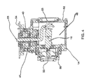
Referring to FIGS. 1 to 4, a two joint module is shown generally at 10. Module 10 includes a first joint 12, a second joint 14 and a module housing 16. The first joint 12 has a first joint axis 28 and the second joint 14 has a second joint axis 46 and the first axis 28 is generally orthogonal to the second axis 46. However, the angle between the two joints need not be orthogonal rather it could be at another angle depending on the design constraints. Typically the first joint is a pitch joint and the second joint is a roll joint or yaw joint.
The first joint 12 includes a first motor 18, a first gearhead 20 and a first drive 22. By way of example the first drive 22 is a harmonic drive. The first motor 20 and first gearhead 18 may be incorporated in the same unit 24 as shown herein. The first motor and gearhead may also include an incremental encoder 21. The motor gearhead is a speed reducer to reduce the power required to operate the first module. The gearhead has a reduction ratio of 20584:1. The use of the gearhead provides for the option to use smaller, lighter and lower power motors. The incremental encoder 21 measures relative rotational position of the motor and in turn by determining the rate of change of the rotational position the speed of the motor is determined. The position of the motor is determined prior to the gearhead. The first drive 22 may include an integrated torque sensor 23 which measures the output torque that is applied after all of the gearing. The first joint also includes an absolute encoder 26 which determines the rotational position of the output after all of the gears. The absolute encoder is used to determine the relative rotational position of the outer link with respect to the inner link.
The first joint 12 has a first motor axis and a first joint axis 28. The first motor 20, first gearhead 18, first drive 22 and first absolute encoder 26 are concentric with the first joint axis 28.
The second joint 14 includes a second motor 32, a second gearhead 30 and a second drive 34. The second motor or drive 34 may be a harmonic drive. The second motor 32 and second gearhead 30 may be incorporated in the same unit 36 as shown herein. The second motor and gearhead may also include an incremental encoder 31. The incremental encoder 31 measures relative rotational position of the motor and from the rate of change of the relative rotational position the speed of the motor is determined. The position of the motor is determined prior to the gearhead. The second drive 34 may include an integrated torque sensor 35 which measures the output torque that is applied after all of the gearing. The second joint also includes an absolute encoder 38 which determines the rotational position of the output after all of the gears. The absolute encoder is used to determine the rotational position of the link.
The second joint 14 includes a hollow drive shaft 40 and angled gearing that allows for internal cabling 41. A worm gear 42 and worm 44 connect the second motor and gearhead combination 36 to the drive shaft 40. This allows the second motor 32, the second motor axis and gearhead combination 36 to be positioned at an angle to the second joint axis 46. The angle may be perpendicular but it will be appreciated by those skilled in the art that the different angles may be chosen depending on the design constraints for the joint. The positioning of the motor and gearhead combination 36 in this fashion allows for a compact two joint module.
The second joint 14 has a second joint axis 46. The second drive 34, second absolute encoder 38 and hollow drive shaft 40 are concentric with the second axis 46. The second drive 34 may be a harmonic drive. The second drive or motor 34, second motor axis and gearhead combination 36 are perpendicular to second joint axis 46. The second motor axis of the second motor and gearhead combination 36 is parallel to the first motor axis of the first motor and gearhead combination 24.
Electronic modules 48 are operably connected to each of the first joint 12 and the second joint 14. The electronic modules 48 are operably connected to a control unit (not shown). The electronic modules 48 receive information from the control unit in regard to the desired movement of the joint and control the first motor 18 and second motor 30 accordingly. Each electronic module 48 includes a torque sensor amplifier to increase strength of the output signal from the torque sensors. Each electronic module 48 includes interfaces for all of the sensors such as the incremental encoders, absolute encoder, and output from torque sensor amplifier, and is capable of digitizing all sensor information. Each electronic module 48 includes power connections.
The module housing 16 includes a first housing cover with electronic connections 53. A first output plate 50 is operably attached to the output of the first drive 22. The output plate 50 is adapted for mechanical external connections and is movable relative to the module housing 16 and output plate 50 is the active side of the housing. The first housing cover 52 with electronic connections 53 is for the joint modules interfaces for power and communications and is used for positioning the link which is attached to the module 10 and first housing cover is the passive side of the housing. The second joint 14 has a combined second output plate 54 and electronic connections 55. The active first output plate 50, passive first housing cover with electronic connections 53 and the second output plate, together with the hollow drive shaft 40 of the second joint 14 allows for internal cabling. However it will be appreciated that the first joint could have a hollow drive shaft and the second joint could have an active and a passive side. The module housing 16 also includes a housing box 56. The module housing box 56 is robust enough to transmit forces and torques and the module housing box is a structural support portion and first joint 12 and second joint 14 are attached thereto. As well, the module housing 16 enclosures the electronics and motors and protects them from external environment. The module housing 16 acts as an electromagnetic shield. The module housing 16 is made from metal and is conductive. The electronics modules 48 are enclosed by the housing 16. The housing 16 provides electromagnetic shielding.
The embodiments of the two joint module 10 shown in FIGS. 1 to 4 are for a small relative to the other joints shown in arm 70 in FIG. 8 and joint module 10 may be used as a wrist module. FIG. 5 shows a medium sized embodiment of a two joint module 60 which is similar to that shown in FIGS. 1 to 4 but is somewhat larger and may be used as an elbow module. Since the elbow joint 60 has a greater distance from the payload, the elbow joint 60 is required to generate greater torques and thus requires larger motors and drives. FIG. 6 show a larger sized embodiment of a two joint module 62 that is similar to modules 10 and 60 but larger and may be used as a shoulder module. FIG. 7 is a larger module similar to that shown in FIG. 6 but further including a fork connector 64. Joint module 62 includes larger motors and drives than those of modules 10 and 60 and can generate higher torques. The electronics are configured so that the joint described herein with internal cabling are capable of being connected in series.
By way of example only the chart below shows the torques that can be generated by the specific joints shown herein. It will be appreciated that the motor size and gear ratios can be varied to achieve the specific torque that is required for a specific application.
MOTOR POWER
JOINT (W) GEAR RATIO TORQUE
Module 62
Shoulder First Joint 50 35652:1 826
Shoulder Second 25 39243:1 367
Joint
Module 60
Elbow First Joint 25 37226:1 334
Elbow Second Joint 5 23085:1 71
Module 10
Wrist First Joint 5 20584:1 65
Wrist Second Joint 5 21309:1 42
As is well known in the art, joints are typically used in conjunctions with links to form a robot arm. The configuration of each robot arm can vary greatly depending on the design specifications which typically include such things as reach, weight of payload to weight of arm, operational environment, dexterity, human machine interfaces, accuracy and repeatability, and control methods. An example of an arm which uses the joint modules of FIGS. 1 to 7 is shown in FIG. 8. Arm 70 includes two joint module 10 as the wrist, two joint module 60 as the elbow and two joint module 62 with fork connector 64 as the shoulder. The modules are connected with links 72. As can be seen from the drawing one advantage of these joints is that there is no external cabling. This is advantageous as it reduces the risk of the cabling getting caught on some unknown projection. Note that in the embodiments shown in FIGS. 1 to 8 the joints have internal cabling. As described above, since the housing 16 provides electromagnetic shielding the cables can be lighter and more bendable since the cables do not need to include shielding or shielded connectors.
The modules can be used with links 72 to form a multi degrees of freedom robotic arm 70. One embodiment of the arm 70 has six degrees of freedom and a reach of 2250 mm. The arm has a mass of 38 kg and a payload capacity of 20 kg. The arm consists of a fork connector 64, shoulder module 62, lower link 72, elbow module 60, upper link 72 and a wrist module 10.
Referring to FIGS. 9 to 16, a two joint module is shown generally at 80. Module 80 includes a first joint 82, a second joint 84 and a module housing 86.
The first joint 82 includes a first motor 88, a first gearhead 90 and a first drive 92. By way of example the first drive may be a harmonic drive. The first motor 88 and first gearhead 90 may be incorporated in the same unit 94 as shown herein. The first motor and gearhead may also include an incremental encoder 91. The incremental encoder 91 measures relative rotational position of the motor and from the rate of change of the relative rotational position the speed of the motor is determined. The position of the motor is determined prior to the gearhead. The first joint also includes an absolute encoder 96 which determines the rotational position of the output after all of the gears. The absolute encoder is used to determine the position of the link.
The first joint 82 has a first joint axis 98. The first motor 88, first gearhead 90, first incremental encoder 91, first drive 92 and first absolute encoder 96 are concentric with the first axis 98. The first motor 88 has a first motor axis.
The second joint 84 includes a second motor 100, a second gearhead 102, a second incremental encoder 103 and a second drive 104. The second drive or motor 104 may be a harmonic drive. The second motor 100, second gearhead 102 and second incremental encoder 103 may be incorporated in the same unit 106 as shown herein. The incremental encoder 103 measures relative rotational position of the motor and from the rate of change of the relative rotational position the speed of the motor is determined. The position of the motor is determined prior to the gearhead. The second joint also includes an absolute encoder 108 which determines the rotational position of the output after all of the gears. The absolute encoder is used to determine the position of the link. A worm gear 112 connects the second motor, gearhead and incremental encoder combination 106 to the second drive 104. This allows the motor and gearhead combination 106 to be positioned perpendicular to the second joint axis 114. The positioning of the motor and gearhead combination 106 in this fashion allows for a compact two joint module.
The second joint 84 has a second axis 114. The second drive or motor 104 has a second motor axis. The second drive 104 and second absolute encoder 108 are concentric with the second axis 114. The second motor, gearhead and incremental encoder combination 106 are perpendicular to second axis 114. The second axis of the second motor, gearhead and incremental encoder combination 106 is parallel to the first axis of the first motor, gearhead and incremental encoder combination 98.
Electronic modules are operably connected to for each of the first joint 82 and the second joint 84. The electronic modules are located in a control unit (not shown). The electronic modules transmit information in regard to the movement of the joint and control the first motor 88 and second motor 100 accordingly. Each electronic module includes interfaces for all of the sensors such as the incremental encoders, absolute encoder, and output from torque sensor amplifier, and is capable of digitizes all sensor information. Each electronic module includes power connections.
The module housing 86 includes first output plate 120 and a second output plate 122. The first output plate 120 and second output plate 122 are adapted for mechanical external connections. The module housing 86 also includes a housing box 124. The housing box 124 acts as a structural support portion and first joint 82 and second joint 84 are attached thereto. The module housing 86 also includes a first motor cover 126 and a second motor cover 128. The first motor cover 126 also includes and external electronic connector 129. The module housing 86 is robust enough to transmit forces and torques. As well, the module housing 86 enclosures the electronics and motors and protects them from external environment. The module housing 86 acts as an electromagnetic shield. The module housing 16 is made from metal and is conductive. The electronics modules 48 are enclosed by the housing 16. The housing 16 provides electromagnetic shielding.
Module 80 is different from those described above in that it is designed for external cabling (not shown).
Two joint module 80 may be used as part of a robotic arm 130 as shown in FIGS. 15 and 16. Module 80 is used herein as a wrist module. Module 80 may be modified to be used as an elbow module 132. As well, module 80 may be scaled up to accommodate different loads.
Elbow module 132 is a two joint module that includes a first joint and a prismatic or linear joint. Module 132 is used herein as an elbow module. Module 132 is an alternative implementation of a two joints. Module 132 may be modified to be used as a wrist module 80 or a shoulder module 134. The first joint of module 132 may be modified and implemented as the first joint in combination with a second joint. A prismatic or linear joint of module 132 may be modified and implemented with second joint. Module 132 shares a common structural element in which both the first joint and the prismatic are attached.
More specifically two joint module 132 includes a first joint 138 and a linear or prismatic joint 140. The first joint 138 includes a first motor 142, a first gearhead 144 and a first drive 146. By way of example the first drive 146 may be a harmonic drive. The first motor 138 and first gearhead 140 may be incorporated in the same unit 148 as shown herein. The first motor and gearhead may also include an incremental encoder 150. The incremental encoder 150 measures relative rotational position of the motor and from the rate of change of the relative rotational position the speed of the motor is determined. The position of the motor is determined prior to the gearhead. The first joint also includes an absolute encoder 152 which determines the rotational position of the output after all of the gears. The absolute encoder is used to determine the position of the link.
The first joint 138 has a first axis 154. The first motor 142, first gearhead 144, first incremental encoder 150, first drive 146 and first absolute encoder 152 are concentric with the pitch axis 154.
The second joint 140 is a linear or prismatic joint includes a first motor 156, a first linear actuator 158. The second joint 140 has a second axis 160. The second motor 156 and second linear actuator 158 are concentric with the second axis 160.
The module housing includes a module base 162 and the first joint 138 and second joint 140 are attached thereto. The module housing further includes a first motor cover 164, a second motor cover 166 and an actuator cover 168 all of which include electromagnetic shielding. An external cable guide 170 is attached to first motor cover 166. External electronic connectors 172 are attached to the external cable guide 170, first motor cover and second motor cover. The external electronic connectors 172 are operably connected to the first joint 138 and the second joint 138.
The two joint modules 80 and 132 may be used in robotic arms. An example of a robotic arm 130 is shown in FIGS. 16 and 17. The modules can be used with a link 136 to form a multi degrees of freedom robotic arm 130. One embodiment of the arm 130 has six degrees of freedom and a reach of 1130 mm. The arm has a mass of 20 kg and a payload capacity of 20 kg. The arm consists of a shoulder and turret joint 134, a shoulder joint 135, a link 136, an elbow and prismatic module 132 and a wrist module 80.
By way of example only the chart below shows the torques that can be generated by the specific joints shown herein. It will be appreciated that the motor size and gear ratios can be varied to achieve the specific torque that is required for a specific application.
MOTOR
JOINT POWER (W) GEAR RATIO TORQUE (NM)
Turret 12 38400:1 73
Shoulder 25 59200:1 258
Elbow Module 132
Elbow First Joint 12 50560:1 123
Elbow Second 4.8 not applicable 200N
Linear Joint
Module
80
Wrist First Joint 12 20480:1 33
Wrist Second Joint 15 38000:1 20
The elbow module 132 and shoulder module 134 may be connected with a link 136.
Generally speaking, the systems described herein are directed to two joint modules. As required, specific embodiments are disclosed herein. However, the disclosed embodiments are merely exemplary, and it should be understood that the disclosure may be embodied in many various and alternative forms. The Figures are not to scale and some features may be exaggerated or minimized to show details of particular elements while related elements may have been eliminated to prevent obscuring novel aspects. Therefore, specific structural and functional details disclosed herein are not to be interpreted as limiting but merely as a basis for the claims and as a representative basis for teaching one skilled in the art to variously employ the present disclosure. For purposes of teaching and not limitation, the illustrated embodiments are directed to two joint modules.
As used herein, the terms “comprises” and “comprising” are to construed as being inclusive and opened rather than exclusive. Specifically, when used in this specification including the claims, the terms “comprises” and “comprising” and variations thereof mean that the specified features, steps or components are included. The terms are not to be interpreted to exclude the presence of other features, steps or components.

Claims (17)

What is claimed is:
1. A robotic arm comprising:
a first link having internal link cables extending from one end to an opposed end thereof;
a first joint operably connected to the first link at one end thereof; the first joint having a hollow drive shaft, an off axis drive and a first joint motor and first joint internal cables extending through the hollow drive shaft;
a second joint operably connected to the first link, the second joint having an active side, a passive side with electronic connectors, second joint internal cables, and a second joint motor and the active side being mechanically connected to the first link; and
wherein the link cables and the first joint cables are operably connected, and the electronic connectors of the passive side on the second joint are operably connected to the link cables.
2. The robotic arm of claim 1 wherein the first joint and the second joint each further includes a gearhead and a drive operably connected to the respective motor.
3. The robotic arm of claim 2 wherein each drive is a harmonic drive.
4. The robotic arm of claim 3 wherein each joint further includes absolute encoders and incremental encoders operably connected to the respective motor.
5. The robotic arm of claim 4 wherein each joint further includes torque sensors.
6. The robotic arm of claim 5 wherein power of the joint is in a range between 5 and 50 W, and torque of the joint is in a range between 20 and 826 N/m.
7. The robotic arm of claim 6 wherein the first motor and gearhead is a combination motor and gearhead.
8. The robotic arm of claim 7 wherein one of the first joint and second joint has a joint axis and the motor has a motor axis and motor axis is at an angle to joint axis.
9. The robotic arm of claim 8 wherein the angle is perpendicular.
10. The robotic arm of claim 9 wherein the other of the first motor and the second motor has a motor axis and wherein the one motor axis is parallel the other motor axis.
11. The robotic arm of claim 10 wherein each joint further includes a housing and the housing acts as an electromagnetic shield.
12. The robotic arm of claim 1 further including a second link operably connected to one of the first joint and the second joint.
13. The robotic arm of claim 12 wherein the first joint and the second joint are a combination two joint module.
14. The robotic arm of claim 13 further including a third joint and a fourth joint each operably connected to the second link.
15. The robotic arm of claim 14 wherein the third joint and the fourth joint are a combination two joint module.
16. The robotic arm of claim 15 further including a fifth joint and a sixth joint.
17. The robotic arm of claim 16 wherein the fifth joint and the sixth joint are a combination two joint module.
US14/728,765 2013-03-07 2015-06-02 Robotic arm Active US9481096B2 (en)

Priority Applications (1)

Application Number Priority Date Filing Date Title
US14/728,765 US9481096B2 (en) 2013-03-07 2015-06-02 Robotic arm

Applications Claiming Priority (2)

Application Number Priority Date Filing Date Title
US13/789,403 US9044865B2 (en) 2013-03-07 2013-03-07 Two joint module
US14/728,765 US9481096B2 (en) 2013-03-07 2015-06-02 Robotic arm

Related Parent Applications (1)

Application Number Title Priority Date Filing Date
US13/789,403 Continuation US9044865B2 (en) 2013-03-07 2013-03-07 Two joint module

Publications (2)

Publication Number Publication Date
US20150290817A1 US20150290817A1 (en) 2015-10-15
US9481096B2 true US9481096B2 (en) 2016-11-01

Family

ID=51385708

Family Applications (2)

Application Number Title Priority Date Filing Date
US13/789,403 Expired - Fee Related US9044865B2 (en) 2013-03-07 2013-03-07 Two joint module
US14/728,765 Active US9481096B2 (en) 2013-03-07 2015-06-02 Robotic arm

Family Applications Before (1)

Application Number Title Priority Date Filing Date
US13/789,403 Expired - Fee Related US9044865B2 (en) 2013-03-07 2013-03-07 Two joint module

Country Status (4)

Country Link
US (2) US9044865B2 (en)
CN (2) CN106625749A (en)
CA (1) CA2843090C (en)
DE (1) DE102014102905A1 (en)

Cited By (1)

* Cited by examiner, † Cited by third party
Publication number Priority date Publication date Assignee Title
US10022861B1 (en) 2017-04-27 2018-07-17 Engineering Services Inc. Two joint module and arm using same

Families Citing this family (25)

* Cited by examiner, † Cited by third party
Publication number Priority date Publication date Assignee Title
JP2016068199A (en) * 2014-09-30 2016-05-09 セイコーエプソン株式会社 robot
CN105818160A (en) * 2015-01-08 2016-08-03 中国科学院上海微系统与信息技术研究所 Universal robot joints and robot arm
CN105983977B (en) * 2015-02-05 2020-08-25 达明机器人股份有限公司 Joint module of robot arm
GB201512964D0 (en) * 2015-07-22 2015-09-02 Cambridge Medical Robotics Ltd Communication paths for robot arms
ITUB20152650A1 (en) * 2015-07-30 2017-01-30 Innovative Eng Search Ltd Industrial robot
CN106541398A (en) * 2015-09-21 2017-03-29 深圳市恒科通机器人有限公司 Combination humanoid robot and its Movable joint mechanism
CN105643654A (en) * 2016-02-19 2016-06-08 上海钧工智能技术有限公司 Reconfigurable modular robot arm pan-tilt head
CN106003008A (en) * 2016-06-15 2016-10-12 上海未来伙伴机器人有限公司 Intelligent motor device of humanoid robot
CN106272536B (en) * 2016-11-02 2018-11-23 中国农业大学 A kind of two-freedom series connection servo joint structure
CN106313105B (en) * 2016-11-02 2018-08-14 中国农业大学 A kind of two-freedom degree joint structure
CN108115658B (en) * 2016-11-26 2021-04-16 沈阳新松机器人自动化股份有限公司 Two-degree-of-freedom modular joint device and robot with same
CN106514697A (en) * 2016-12-09 2017-03-22 中国科学院合肥物质科学研究院 Two-freedom-degree orthogonal type robot joint module and six-freedom-degree mechanical arm
CN107042507B (en) * 2017-03-16 2023-07-28 广东省智能制造研究所 Multi-degree-of-freedom driving arm and double-arm robot adopting same
CN107225597B (en) * 2017-07-24 2020-05-15 中国电子科技集团公司第二十一研究所 Two-degree-of-freedom modular joint assembly based on hollow integrated motor
JP7007839B2 (en) * 2017-08-31 2022-01-25 川崎重工業株式会社 Articulated robot
CN107498579B (en) * 2017-09-11 2023-07-21 清华大学深圳研究生院 Joint connection device of mechanical arm based on limit beads
CN108908394A (en) * 2018-10-08 2018-11-30 哈尔滨工业大学 A kind of compact composite joint for mechanical arm pitching and revolution
CN109533075B (en) * 2018-12-04 2023-10-03 深圳信息职业技术学院 Biped wall climbing robot
CN109551510B (en) * 2018-12-20 2023-10-03 广东工业大学 Driving and control integrated moment measurable and controllable robot rotary joint module
CN109551482B (en) * 2018-12-20 2023-10-03 广东工业大学 Driving and control integrated moment-measurable robot swing joint module
CN110253618A (en) * 2019-07-08 2019-09-20 河海大学常州校区 Joint of mechanical arm under a kind of motor-driven modular water
CN110253554A (en) * 2019-07-08 2019-09-20 河海大学常州校区 A kind of modularization detection mechanical arm of underwater works
CN110695966B (en) * 2019-10-11 2022-12-13 成都双创时代科技有限公司 High-precision robot power box and application thereof
WO2023107266A1 (en) * 2021-12-10 2023-06-15 Boston Dynamics, Inc. Systems and methods for actuation of a robotic manipulator
CN113927630A (en) * 2021-12-20 2022-01-14 沈阳新松机器人自动化股份有限公司 Rotary joint wiring structure

Citations (16)

* Cited by examiner, † Cited by third party
Publication number Priority date Publication date Assignee Title
US5101681A (en) * 1987-06-09 1992-04-07 Ameus Corporation Interlocking-body connective joints
US5673595A (en) 1995-05-19 1997-10-07 Canadian Space Agency Four degree-of-freedom manipulator
US5712552A (en) * 1993-10-01 1998-01-27 Kabushiki Kaisha Yaskawa Denki No-wiring robot
US6394998B1 (en) 1999-01-22 2002-05-28 Intuitive Surgical, Inc. Surgical tools for use in minimally invasive telesurgical applications
CN1876335A (en) 2006-07-10 2006-12-13 东南大学 Joint structure for rehabilitation training robot
US20070208458A1 (en) * 2006-03-01 2007-09-06 Kawasaki Jukogyo Kabushiki Kaisha Industrial robot
CN101579860A (en) 2009-06-04 2009-11-18 浙江大学 Double-T type waist joint structure of humanoid robot
US20100192720A1 (en) 2006-10-31 2010-08-05 Force Dimension S.A.R.L Parallel Kinematic Structure
US20100242660A1 (en) 2009-03-30 2010-09-30 Ge-Hitachi Nuclear Energy Americas Llc Manipulator for remote activities in a nuclear reactor vessel
US20110296944A1 (en) 2010-06-02 2011-12-08 Disney Enterprises, Inc. Three-axis robotic joint using four-bar linkages to drive differential side gears
US20120192671A1 (en) 2009-10-05 2012-08-02 Commissariat A L'energie Atomique Et Aux Energies Alternatives Motor-driven self-locking articulation for a robot arm
US20120204670A1 (en) 2010-02-05 2012-08-16 The Regents Of The University Of California Four degree of freedom (4-dof) single modular robot unit or joint
CN102862165A (en) 2012-09-25 2013-01-09 杭州电子科技大学 Double-degree-of-freedom robot shoulder joint steering engine
US20130068060A1 (en) 2011-09-16 2013-03-21 Hon Hai Precision Industry Co., Ltd. Flexspline protective structure and robot arm mechanism using same
US20140026705A1 (en) 2011-03-30 2014-01-30 Squse Inc. Scott russell mechanism device
US20140060233A1 (en) 2012-08-31 2014-03-06 Seiko Epson Corporation Robot

Family Cites Families (8)

* Cited by examiner, † Cited by third party
Publication number Priority date Publication date Assignee Title
GB8710305D0 (en) * 1987-04-30 1987-06-03 Manchester Inst Science Tech Mechanism
DE4242575C2 (en) * 1991-12-17 1997-04-30 Toshiba Kawasaki Kk Joint module for a manipulator
US5697256A (en) * 1996-06-28 1997-12-16 Matteo; Joseph C. Hybrid differential transmission
JP4142304B2 (en) * 2001-10-22 2008-09-03 株式会社安川電機 Arc welding robot
KR100460083B1 (en) * 2003-10-31 2004-12-08 주식회사 세진아이지비 Articulated robot module having intersecting axes
US8006586B2 (en) * 2007-03-12 2011-08-30 Comau S.P.A. Articulated robot wrist
CN102811843A (en) * 2010-09-03 2012-12-05 Abb研究有限公司 An Industrial Robot, A Component System For A Such And A Method For Assembling A Such
CN102744731B (en) * 2012-07-19 2014-07-02 北京理工大学 Integral rotary joint and method for determining zero position of integral rotary joint

Patent Citations (16)

* Cited by examiner, † Cited by third party
Publication number Priority date Publication date Assignee Title
US5101681A (en) * 1987-06-09 1992-04-07 Ameus Corporation Interlocking-body connective joints
US5712552A (en) * 1993-10-01 1998-01-27 Kabushiki Kaisha Yaskawa Denki No-wiring robot
US5673595A (en) 1995-05-19 1997-10-07 Canadian Space Agency Four degree-of-freedom manipulator
US6394998B1 (en) 1999-01-22 2002-05-28 Intuitive Surgical, Inc. Surgical tools for use in minimally invasive telesurgical applications
US20070208458A1 (en) * 2006-03-01 2007-09-06 Kawasaki Jukogyo Kabushiki Kaisha Industrial robot
CN1876335A (en) 2006-07-10 2006-12-13 东南大学 Joint structure for rehabilitation training robot
US20100192720A1 (en) 2006-10-31 2010-08-05 Force Dimension S.A.R.L Parallel Kinematic Structure
US20100242660A1 (en) 2009-03-30 2010-09-30 Ge-Hitachi Nuclear Energy Americas Llc Manipulator for remote activities in a nuclear reactor vessel
CN101579860A (en) 2009-06-04 2009-11-18 浙江大学 Double-T type waist joint structure of humanoid robot
US20120192671A1 (en) 2009-10-05 2012-08-02 Commissariat A L'energie Atomique Et Aux Energies Alternatives Motor-driven self-locking articulation for a robot arm
US20120204670A1 (en) 2010-02-05 2012-08-16 The Regents Of The University Of California Four degree of freedom (4-dof) single modular robot unit or joint
US20110296944A1 (en) 2010-06-02 2011-12-08 Disney Enterprises, Inc. Three-axis robotic joint using four-bar linkages to drive differential side gears
US20140026705A1 (en) 2011-03-30 2014-01-30 Squse Inc. Scott russell mechanism device
US20130068060A1 (en) 2011-09-16 2013-03-21 Hon Hai Precision Industry Co., Ltd. Flexspline protective structure and robot arm mechanism using same
US20140060233A1 (en) 2012-08-31 2014-03-06 Seiko Epson Corporation Robot
CN102862165A (en) 2012-09-25 2013-01-09 杭州电子科技大学 Double-degree-of-freedom robot shoulder joint steering engine

Non-Patent Citations (3)

* Cited by examiner, † Cited by third party
Title
E.T. Baumgartner, R.G. Bonitz, J.P. Melko, L.R. Shiraishi and P.C. Leger, "The Mars Exploration Rover Instrument Positioning System," Proceedings of the 2005 IEEE Aerospace Conference, Big Sky, MT, Mar. 2005.
P. Schenker et al., "Dexterous Robotic Sampling for Mars in-situ Science", Publication date Oct. 14, 1999, conference paper International Society for Optical Engineering (SPIE); Pittsburgh, PA, United States.
Schunk, Servo-electric rotary pan-tilt actuator Type PW 70-90 Assembly and operating manual, Trans., 02.01 ed., Lauffen/Neckar, Schunk GmbH & Co. KG, Aug. 14, 2012. Print.

Cited By (1)

* Cited by examiner, † Cited by third party
Publication number Priority date Publication date Assignee Title
US10022861B1 (en) 2017-04-27 2018-07-17 Engineering Services Inc. Two joint module and arm using same

Also Published As

Publication number Publication date
CN106625749A (en) 2017-05-10
US9044865B2 (en) 2015-06-02
DE102014102905A1 (en) 2014-09-11
CA2843090A1 (en) 2014-09-07
CN104029213B (en) 2017-06-09
CA2843090C (en) 2017-10-24
US20150290817A1 (en) 2015-10-15
CN104029213A (en) 2014-09-10
US20140251054A1 (en) 2014-09-11

Similar Documents

Publication Publication Date Title
US9481096B2 (en) Robotic arm
US9802327B2 (en) Robot arm and robot
US9321179B2 (en) Wrist structure of industrial robot
KR20190103032A (en) Actuator, robot arm and robot
KR101437767B1 (en) Geared type gravity compensating unit
KR102123935B1 (en) robot
US20120266712A1 (en) Robot
US9895800B2 (en) Robot, robot control device, and robot system
US20120266720A1 (en) Drive apparatus and robot
WO2021062635A1 (en) Joint structure and robot
GB2481249A (en) Three dimensional selective compliant robot
JP6088362B2 (en) Industrial robot wrist drive structure with 3 degrees of freedom of rotation
CN105479482A (en) Wrist of six-axis robot arm
CN212218476U (en) Torque-controllable rotary driver and robot system
US20180372195A1 (en) Linear extension and retraction mechanism and robot arm mechanism
JP2015142948A (en) actuator
CN108687795B (en) Robot
US10744639B2 (en) Parallel link robot and operation apparatus
Klas et al. A compact, lightweight and singularity-free wrist joint mechanism for humanoid robots
WO2021144969A1 (en) Biaxial integrated module and multijoint robot arm device
CN211415236U (en) Driving joint based on double-stator frameless torque motor and industrial robot
CN106808469B (en) Mechanical arm transmission joint mechanism with force position measuring function
Burisch et al. Investigation and strategies for precision of miniaturized robots with micro gears
WO2021144967A1 (en) Module and vertical articulated robot arm device
JP2019130609A (en) Horizontal multi-joint robot

Legal Events

Date Code Title Description
AS Assignment

Owner name: ENGINEERING SERVICES INC., CANADA

Free format text: ASSIGNMENT OF ASSIGNORS INTEREST;ASSIGNORS:GOLDENBERG, ANDREW A.;BAILEY, BRENT;GRYNIEWSKI, MATTHEW;AND OTHERS;SIGNING DATES FROM 20130315 TO 20130318;REEL/FRAME:036271/0513

STCF Information on status: patent grant

Free format text: PATENTED CASE

AS Assignment

Owner name: ENGINEERING SERVICES INC., CANADA

Free format text: CHANGE OF ADDRESS;ASSIGNOR:ENGINEERING SERVICES INC.;REEL/FRAME:044287/0673

Effective date: 20170828

AS Assignment

Owner name: CHINA SUPERROBOTICS LIMITED, CHINA

Free format text: ASSIGNMENT OF ASSIGNORS INTEREST;ASSIGNOR:ENGINEERING SERVICES INC.;REEL/FRAME:051382/0708

Effective date: 20191225

AS Assignment

Owner name: CHINA SUPERROBOTICS LIMITED, CHINA

Free format text: CORRECTIVE ASSIGNMENT TO CORRECT THE LIST OF ASSIGNED PROPERTIES PREVIOUSLY RECORDED AT REEL: 051382 FRAME: 0708. ASSIGNOR(S) HEREBY CONFIRMS THE ASSIGNMENT;ASSIGNOR:ENGINEERING SERVICES INC.;REEL/FRAME:051501/0789

Effective date: 20191225

FEPP Fee payment procedure

Free format text: MAINTENANCE FEE REMINDER MAILED (ORIGINAL EVENT CODE: REM.); ENTITY STATUS OF PATENT OWNER: SMALL ENTITY

FEPP Fee payment procedure

Free format text: SURCHARGE FOR LATE PAYMENT, SMALL ENTITY (ORIGINAL EVENT CODE: M2554); ENTITY STATUS OF PATENT OWNER: SMALL ENTITY

MAFP Maintenance fee payment

Free format text: PAYMENT OF MAINTENANCE FEE, 4TH YR, SMALL ENTITY (ORIGINAL EVENT CODE: M2551); ENTITY STATUS OF PATENT OWNER: SMALL ENTITY

Year of fee payment: 4