US9480952B2 - Methods for chemical reaction perforation of atomically thin materials - Google Patents
Methods for chemical reaction perforation of atomically thin materials Download PDFInfo
- Publication number
- US9480952B2 US9480952B2 US14/200,195 US201414200195A US9480952B2 US 9480952 B2 US9480952 B2 US 9480952B2 US 201414200195 A US201414200195 A US 201414200195A US 9480952 B2 US9480952 B2 US 9480952B2
- Authority
- US
- United States
- Prior art keywords
- lattice
- graphene
- holes
- cutter
- molecule
- Prior art date
- Legal status (The legal status is an assumption and is not a legal conclusion. Google has not performed a legal analysis and makes no representation as to the accuracy of the status listed.)
- Expired - Fee Related, expires
Links
- 238000000034 method Methods 0.000 title claims abstract description 51
- 239000000463 material Substances 0.000 title claims description 28
- 238000006243 chemical reaction Methods 0.000 title description 7
- 238000005520 cutting process Methods 0.000 claims abstract description 7
- OKTJSMMVPCPJKN-UHFFFAOYSA-N Carbon Chemical compound [C] OKTJSMMVPCPJKN-UHFFFAOYSA-N 0.000 claims description 89
- 229910021389 graphene Inorganic materials 0.000 claims description 88
- 239000011203 carbon fibre reinforced carbon Substances 0.000 claims description 16
- 125000001424 substituent group Chemical group 0.000 claims description 14
- BBEAQIROQSPTKN-UHFFFAOYSA-N pyrene Chemical compound C1=CC=C2C=CC3=CC=CC4=CC=C1C2=C43 BBEAQIROQSPTKN-UHFFFAOYSA-N 0.000 claims description 7
- 229910052582 BN Inorganic materials 0.000 claims description 6
- PZNSFCLAULLKQX-UHFFFAOYSA-N Boron nitride Chemical compound N#B PZNSFCLAULLKQX-UHFFFAOYSA-N 0.000 claims description 6
- MWPLVEDNUUSJAV-UHFFFAOYSA-N anthracene Chemical compound C1=CC=CC2=CC3=CC=CC=C3C=C21 MWPLVEDNUUSJAV-UHFFFAOYSA-N 0.000 claims description 6
- 125000004430 oxygen atom Chemical group O* 0.000 claims description 6
- GVEPBJHOBDJJJI-UHFFFAOYSA-N fluoranthrene Natural products C1=CC(C2=CC=CC=C22)=C3C2=CC=CC3=C1 GVEPBJHOBDJJJI-UHFFFAOYSA-N 0.000 claims description 4
- 230000001590 oxidative effect Effects 0.000 claims description 4
- CXRFFSKFQFGBOT-UHFFFAOYSA-N bis(selanylidene)niobium Chemical compound [Se]=[Nb]=[Se] CXRFFSKFQFGBOT-UHFFFAOYSA-N 0.000 claims description 3
- CWQXQMHSOZUFJS-UHFFFAOYSA-N molybdenum disulfide Chemical compound S=[Mo]=S CWQXQMHSOZUFJS-UHFFFAOYSA-N 0.000 claims description 3
- 229910052762 osmium Inorganic materials 0.000 claims description 3
- SYQBFIAQOQZEGI-UHFFFAOYSA-N osmium atom Chemical group [Os] SYQBFIAQOQZEGI-UHFFFAOYSA-N 0.000 claims description 3
- 125000002080 perylenyl group Chemical group C1(=CC=C2C=CC=C3C4=CC=CC5=CC=CC(C1=C23)=C45)* 0.000 claims description 3
- CSHWQDPOILHKBI-UHFFFAOYSA-N peryrene Natural products C1=CC(C2=CC=CC=3C2=C2C=CC=3)=C3C2=CC=CC3=C1 CSHWQDPOILHKBI-UHFFFAOYSA-N 0.000 claims description 3
- 229910021428 silicene Inorganic materials 0.000 claims description 3
- UFHFLCQGNIYNRP-UHFFFAOYSA-N Hydrogen Chemical compound [H][H] UFHFLCQGNIYNRP-UHFFFAOYSA-N 0.000 claims 1
- UFWIBTONFRDIAS-UHFFFAOYSA-N Naphthalene Chemical compound C1=CC=CC2=CC=CC=C21 UFWIBTONFRDIAS-UHFFFAOYSA-N 0.000 claims 1
- 229910052739 hydrogen Inorganic materials 0.000 claims 1
- 239000001257 hydrogen Substances 0.000 claims 1
- 125000004432 carbon atom Chemical group C* 0.000 description 18
- 239000012528 membrane Substances 0.000 description 16
- 229910052751 metal Inorganic materials 0.000 description 16
- 239000002184 metal Substances 0.000 description 16
- 125000004429 atom Chemical group 0.000 description 12
- 230000008569 process Effects 0.000 description 12
- 229910052799 carbon Inorganic materials 0.000 description 11
- 230000003647 oxidation Effects 0.000 description 9
- 238000007254 oxidation reaction Methods 0.000 description 9
- UHOVQNZJYSORNB-UHFFFAOYSA-N Benzene Chemical group C1=CC=CC=C1 UHOVQNZJYSORNB-UHFFFAOYSA-N 0.000 description 6
- 230000007547 defect Effects 0.000 description 6
- 238000001914 filtration Methods 0.000 description 6
- 239000000126 substance Substances 0.000 description 6
- QVGXLLKOCUKJST-UHFFFAOYSA-N atomic oxygen Chemical compound [O] QVGXLLKOCUKJST-UHFFFAOYSA-N 0.000 description 5
- 238000003776 cleavage reaction Methods 0.000 description 5
- 238000009826 distribution Methods 0.000 description 5
- 230000006911 nucleation Effects 0.000 description 5
- 238000010899 nucleation Methods 0.000 description 5
- 239000001301 oxygen Substances 0.000 description 5
- 229910052760 oxygen Inorganic materials 0.000 description 5
- 230000007017 scission Effects 0.000 description 5
- XLYOFNOQVPJJNP-UHFFFAOYSA-N water Substances O XLYOFNOQVPJJNP-UHFFFAOYSA-N 0.000 description 5
- XKRFYHLGVUSROY-UHFFFAOYSA-N Argon Chemical compound [Ar] XKRFYHLGVUSROY-UHFFFAOYSA-N 0.000 description 4
- 125000003118 aryl group Chemical group 0.000 description 4
- 238000010612 desalination reaction Methods 0.000 description 4
- BASFCYQUMIYNBI-UHFFFAOYSA-N platinum Chemical compound [Pt] BASFCYQUMIYNBI-UHFFFAOYSA-N 0.000 description 4
- 239000013535 sea water Substances 0.000 description 4
- 238000013459 approach Methods 0.000 description 3
- 238000010504 bond cleavage reaction Methods 0.000 description 3
- 239000007789 gas Substances 0.000 description 3
- 238000004519 manufacturing process Methods 0.000 description 3
- 238000001020 plasma etching Methods 0.000 description 3
- 229920003229 poly(methyl methacrylate) Polymers 0.000 description 3
- 239000004926 polymethyl methacrylate Substances 0.000 description 3
- -1 salt ions Chemical class 0.000 description 3
- MQMYRABGDSRTGR-UHFFFAOYSA-N [C].C1=CC=C2C=CC3=CC=CC4=CC=C1C2=C43 Chemical compound [C].C1=CC=C2C=CC3=CC=CC4=CC=C1C2=C43 MQMYRABGDSRTGR-UHFFFAOYSA-N 0.000 description 2
- 229910052782 aluminium Inorganic materials 0.000 description 2
- XAGFODPZIPBFFR-UHFFFAOYSA-N aluminium Chemical compound [Al] XAGFODPZIPBFFR-UHFFFAOYSA-N 0.000 description 2
- 229910052786 argon Inorganic materials 0.000 description 2
- 230000008901 benefit Effects 0.000 description 2
- 230000015572 biosynthetic process Effects 0.000 description 2
- 238000011161 development Methods 0.000 description 2
- 230000018109 developmental process Effects 0.000 description 2
- 238000007306 functionalization reaction Methods 0.000 description 2
- 125000004435 hydrogen atom Chemical group [H]* 0.000 description 2
- 230000003993 interaction Effects 0.000 description 2
- 150000002500 ions Chemical class 0.000 description 2
- 150000002739 metals Chemical class 0.000 description 2
- 229910052982 molybdenum disulfide Inorganic materials 0.000 description 2
- 229910052697 platinum Inorganic materials 0.000 description 2
- 229920000642 polymer Polymers 0.000 description 2
- 150000003220 pyrenes Chemical class 0.000 description 2
- 238000006467 substitution reaction Methods 0.000 description 2
- 230000032258 transport Effects 0.000 description 2
- STOOCEMZTICZLU-YBUFYNRRSA-N C[C@@](CN)(CC1CC(CC(CC(CCC2CC3)C4C2C2C3C3CCC5C(CCC6CC7)C8C6C6C7C7)C9C4C4C2C2C3C5C3C8C5C6C6C7CC7CC8CC%10CC(CC(CCC%11)C%12C%11C%11CC%13)C%14C%12C%12C%11C%11C%13C%13CC%15)C%16C9C9C4C4C2C3C2C5C3C6C7C5C8C6C%10C%14C7C%12C8C%11C%10C%13C%11C%15C(CCC%12)C%13C%12C%12)C%14C%15C%17C%18C%19C%20C%21C%22C%23C%24C%25C%21C%21C%19C%15C1C%16C%21C9C%25C4C2C%24C3C5C%23C6C7C%22C8C%20C%10C%18C%11C%13C%17C%12C%14CCN=O Chemical compound C[C@@](CN)(CC1CC(CC(CC(CCC2CC3)C4C2C2C3C3CCC5C(CCC6CC7)C8C6C6C7C7)C9C4C4C2C2C3C5C3C8C5C6C6C7CC7CC8CC%10CC(CC(CCC%11)C%12C%11C%11CC%13)C%14C%12C%12C%11C%11C%13C%13CC%15)C%16C9C9C4C4C2C3C2C5C3C6C7C5C8C6C%10C%14C7C%12C8C%11C%10C%13C%11C%15C(CCC%12)C%13C%12C%12)C%14C%15C%17C%18C%19C%20C%21C%22C%23C%24C%25C%21C%21C%19C%15C1C%16C%21C9C%25C4C2C%24C3C5C%23C6C7C%22C8C%20C%10C%18C%11C%13C%17C%12C%14CCN=O STOOCEMZTICZLU-YBUFYNRRSA-N 0.000 description 1
- AZDRQVAHHNSJOQ-UHFFFAOYSA-N alumane Chemical class [AlH3] AZDRQVAHHNSJOQ-UHFFFAOYSA-N 0.000 description 1
- 238000004458 analytical method Methods 0.000 description 1
- 230000009286 beneficial effect Effects 0.000 description 1
- 229920001400 block copolymer Polymers 0.000 description 1
- 238000004364 calculation method Methods 0.000 description 1
- 150000001721 carbon Chemical group 0.000 description 1
- 239000003054 catalyst Substances 0.000 description 1
- 230000008859 change Effects 0.000 description 1
- 238000012512 characterization method Methods 0.000 description 1
- 239000002131 composite material Substances 0.000 description 1
- 125000004122 cyclic group Chemical group 0.000 description 1
- 238000010586 diagram Methods 0.000 description 1
- 238000009792 diffusion process Methods 0.000 description 1
- 230000000694 effects Effects 0.000 description 1
- 238000005516 engineering process Methods 0.000 description 1
- 239000012530 fluid Substances 0.000 description 1
- 230000006870 function Effects 0.000 description 1
- 230000036571 hydration Effects 0.000 description 1
- 238000006703 hydration reaction Methods 0.000 description 1
- 230000037427 ion transport Effects 0.000 description 1
- 230000007246 mechanism Effects 0.000 description 1
- 238000000329 molecular dynamics simulation Methods 0.000 description 1
- 239000002105 nanoparticle Substances 0.000 description 1
- 239000002064 nanoplatelet Substances 0.000 description 1
- 239000002074 nanoribbon Substances 0.000 description 1
- 239000007800 oxidant agent Substances 0.000 description 1
- 239000002245 particle Substances 0.000 description 1
- 238000002161 passivation Methods 0.000 description 1
- 238000000059 patterning Methods 0.000 description 1
- 230000002093 peripheral effect Effects 0.000 description 1
- 125000001997 phenyl group Chemical group [H]C1=C([H])C([H])=C(*)C([H])=C1[H] 0.000 description 1
- 125000003367 polycyclic group Polymers 0.000 description 1
- 238000000746 purification Methods 0.000 description 1
- 238000001223 reverse osmosis Methods 0.000 description 1
- 150000003839 salts Chemical class 0.000 description 1
- 238000000926 separation method Methods 0.000 description 1
- 238000007873 sieving Methods 0.000 description 1
- 239000007921 spray Substances 0.000 description 1
- 238000003860 storage Methods 0.000 description 1
- 239000000758 substrate Substances 0.000 description 1
Images


Classifications
-
- B—PERFORMING OPERATIONS; TRANSPORTING
- B01—PHYSICAL OR CHEMICAL PROCESSES OR APPARATUS IN GENERAL
- B01D—SEPARATION
- B01D67/00—Processes specially adapted for manufacturing semi-permeable membranes for separation processes or apparatus
- B01D67/0039—Inorganic membrane manufacture
- B01D67/0053—Inorganic membrane manufacture by inducing porosity into non porous precursor membranes
-
- B—PERFORMING OPERATIONS; TRANSPORTING
- B01—PHYSICAL OR CHEMICAL PROCESSES OR APPARATUS IN GENERAL
- B01D—SEPARATION
- B01D65/00—Accessories or auxiliary operations, in general, for separation processes or apparatus using semi-permeable membranes
- B01D65/10—Testing of membranes or membrane apparatus; Detecting or repairing leaks
- B01D65/106—Repairing membrane apparatus or modules
- B01D65/108—Repairing membranes
-
- B—PERFORMING OPERATIONS; TRANSPORTING
- B01—PHYSICAL OR CHEMICAL PROCESSES OR APPARATUS IN GENERAL
- B01D—SEPARATION
- B01D67/00—Processes specially adapted for manufacturing semi-permeable membranes for separation processes or apparatus
- B01D67/0039—Inorganic membrane manufacture
- B01D67/0053—Inorganic membrane manufacture by inducing porosity into non porous precursor membranes
- B01D67/006—Inorganic membrane manufacture by inducing porosity into non porous precursor membranes by elimination of segments of the precursor, e.g. nucleation-track membranes, lithography or laser methods
-
- B—PERFORMING OPERATIONS; TRANSPORTING
- B01—PHYSICAL OR CHEMICAL PROCESSES OR APPARATUS IN GENERAL
- B01D—SEPARATION
- B01D71/00—Semi-permeable membranes for separation processes or apparatus characterised by the material; Manufacturing processes specially adapted therefor
- B01D71/02—Inorganic material
- B01D71/021—Carbon
- B01D71/0211—Graphene or derivates thereof
-
- B—PERFORMING OPERATIONS; TRANSPORTING
- B82—NANOTECHNOLOGY
- B82Y—SPECIFIC USES OR APPLICATIONS OF NANOSTRUCTURES; MEASUREMENT OR ANALYSIS OF NANOSTRUCTURES; MANUFACTURE OR TREATMENT OF NANOSTRUCTURES
- B82Y40/00—Manufacture or treatment of nanostructures
-
- C01B31/0438—
-
- C01B31/0446—
-
- C01B31/0484—
-
- C—CHEMISTRY; METALLURGY
- C01—INORGANIC CHEMISTRY
- C01B—NON-METALLIC ELEMENTS; COMPOUNDS THEREOF; METALLOIDS OR COMPOUNDS THEREOF NOT COVERED BY SUBCLASS C01C
- C01B32/00—Carbon; Compounds thereof
- C01B32/15—Nano-sized carbon materials
- C01B32/182—Graphene
- C01B32/184—Preparation
-
- C—CHEMISTRY; METALLURGY
- C01—INORGANIC CHEMISTRY
- C01B—NON-METALLIC ELEMENTS; COMPOUNDS THEREOF; METALLOIDS OR COMPOUNDS THEREOF NOT COVERED BY SUBCLASS C01C
- C01B32/00—Carbon; Compounds thereof
- C01B32/15—Nano-sized carbon materials
- C01B32/182—Graphene
- C01B32/194—After-treatment
-
- H01L29/1606—
-
- H—ELECTRICITY
- H10—SEMICONDUCTOR DEVICES; ELECTRIC SOLID-STATE DEVICES NOT OTHERWISE PROVIDED FOR
- H10D—INORGANIC ELECTRIC SEMICONDUCTOR DEVICES
- H10D62/00—Semiconductor bodies, or regions thereof, of devices having potential barriers
- H10D62/80—Semiconductor bodies, or regions thereof, of devices having potential barriers characterised by the materials
- H10D62/881—Semiconductor bodies, or regions thereof, of devices having potential barriers characterised by the materials being a two-dimensional material
- H10D62/882—Graphene
Definitions
- the present invention is generally directed to the formation of perforations in atomically thin materials. More particularly, the present invention relates to a method of chemically cleaving an opening in an atomically thin material such as graphene so as to provide precisely sized apertures in the nanometer range.
- a graphene membrane is a single-atomic-layer-thick layer of carbon atoms, bound together to define a sheet.
- the thickness of a single graphene membrane which may be referred to as a layer or a sheet, is approximately 0.2 to 0.3 nanometers (nm) thick, or as sometimes referred to herein “thin.”
- the carbon atoms of the graphene layer define a repeating pattern of hexagonal ring structures (benzene rings) constructed of six carbon atoms, which form a honeycomb lattice of carbon atoms.
- An interstitial aperture is formed by each six carbon atom ring structure in the sheet and this interstitial aperture is less than one nanometer across.
- interstitial aperture is believed to be about 0.23 nanometers across at its longest dimension. Accordingly, the dimension and configuration of the interstitial aperture and the electron nature of the graphene precludes transport of any molecule across the graphene's thickness unless there are perforations.
- the carbon atoms in graphene, or other atoms in an atomically thin layer are so closely spaced that a sheet or layer of the material is essentially impermeable to most substances.
- holes with the proper dimensions are made in the layer, molecules smaller than these holes can readily pass through the layer. Molecules with dimensions larger than the holes will not be able pass through the layer.
- a layer with properly sized holes is a “molecular filter,” and it can be used to separate molecules based on their size differences. With properly sized holes, a perforated graphene layer becomes a nano-filter or ultra-filter. Because of its extreme thinness, the energy cost for moving a molecule across such a molecular membrane is lower than other competing filtration membranes that rely on Solution-Diffusion mechanisms for separation.
- a P(S-blockMMA) block copolymer forms an array of PMMA columns that form vias for the RIE upon redeveloping.
- the pattern of holes is very dense. The number and size of holes is controlled by the molecular weight of the PMMA block and the weight fraction of the PMMA in the P(S-MMA). Either method has the potential to produce perforated graphene sheets.
- Chemical methods (such as oxidation or doping) of creating holes in graphene generally operate by nucleating defects in the graphene lattice and growing holes through bond breaking at these defects. Since the defect nucleation and hole growth occur simultaneously across the graphene, a wide range of hole sizes is created. It is difficult to control the oxidation process to simultaneously keep hole dimensions small (nanoscopic) and the hole distribution narrow.
- the above-mentioned methodologies create nanometer sized holes in graphene, but the preponderance of holes created are not in the size range (below 10 nm diameter) required for applications such as desalination. Although the above methodologies are adequate at forming a desired size of hole, several of those methods do not consistently provide the same size holes. For example, an operation to form holes may generate some holes having a diameter of 1.2 nm and other holes having a diameter of 2.5 nm. Typically, methods such as oxidation that create holes via initial nucleation of defects in graphene followed by growth of holes yield a range of hole sizes because the nucleation and growth processes proceed at the same time.
- FIG. 1 is a schematic representation of a graphene lattice or membrane according to the concepts of the present invention
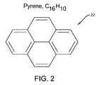
- FIG. 2 is a diagram of an exemplary cutter molecule according to the concepts of the present invention.
- FIG. 3 is a schematic representation of the cutter molecule overlaying the graphene lattice according to the concepts of the present invention
- FIG. 4 is a schematic representation of a hole formed by the cutter molecule in the graphene lattice according to the concepts of the present invention
- FIG. 5 is an example of another potential cutter molecule, such as Napthelene, according to the concepts of the present invention.
- FIG. 6 is an example of another potential cutter molecule, such as a variation of Napthelene, according to the concepts of the present invention
- FIG. 7 is an example of another potential cutter molecule, such as Anthracene, according to the concepts of the present invention
- FIG. 8 is an example of another potential cutter molecule, such as Perylene, according to the concepts of the present invention.
- FIGS. 9A, 9B, 10A, 10B, 11A, 11B, 12A, 12B, 13A, and 13B are schematic representations of graphene lattices with holes wherein different numbers of carbon atoms are missing from the lattice and wherein carbon-oxygen bonds are or are not added to terminate hole edges.
- FIGS. 9A, 10A, 11A, 12A, and 13A are examples of different sized lattice holes in a graphene lattice. These figures are intended to be illustrative of the relation between hole size and shape and number of lattice carbon atoms missing.
- FIGS. 9B, 10B, 11B, 12B, and 13B are similar to the corresponding “A” Figs.
- the present invention uses a carrier molecule with reactive substituents on its periphery to “cut” the molecular bonds in an atomically thin lattice, layer or membrane, thereby removing a piece of the lattice and leaving behind a hole.
- the carrier molecule cuts the carbon-carbon bonds of the lattice or membrane.
- the hole geometry is defined by the shape and size of the carrier molecule.
- the reactive substituents on the carrier molecule enable cleavage of molecular bonds, thereby breaking neighboring bonds holding a portion of lattice structure. When that portion leaves, the hole left has a size/shape defined by the size/shape of the carrier molecule.
- a key technical enabler for an atomically thin material used in molecular filter technology or other applications is the ability to make holes, apertures, or perforations in an atomically thin material of desired dimensional range. Indeed, it is desired to form uniform nanometer (molecular sized) apertures having a range of 0.3 to 10 nm in size, and in some applications the aperture size can range from 0.5 nm up to 100 nm or more. For example purposes only, water and ion transport across a graphene layer with a hole of variable size was modeled and resulting hole sizes and the number of carbon atoms that must be removed from a graphene lattice to create these holes was established. As seen in the Table below, the analysis of the graphene structure and a desired hole size is presented.
- the resulting membrane can be used to remove unwanted species from a fluid (or gas), or capture a rare but desired species by enriching its concentration in a solution (or gas).
- Purification of seawater by reverse osmosis through a perforated graphene filter becomes possible if the graphene holes are on the order of or smaller than seawater salt ions hydration radii.
- Other embodiments can provide holes that range from 0.5 nm to 2.2 nm.
- hole nucleation is replaced by reaction chemistry at the periphery of the carrier molecule, and hole size is determined by the physical dimensions of that molecule, rather than growth of a hole.
- hole growth kinetics there is no hole growth kinetics in the following process, although subsequent hole growth processes (such as mild oxidation) could be applied to further enlarge holes formed by this method, thereby preserving the monodispersity for larger desired hole sizes.
- all holes are of the same size, as determined by the carrier molecule size. As long as the size distribution of carrier molecules is monodisperse, the hole sizes will likewise be monodisperse.
- FIGS. 1-4 a methodology for forming a lattice with precisely sized holes is disclosed.
- specific reference is made to graphene; however skilled artisans will appreciate that the methodology disclosed herein is applicable to the formation of consistently sized apertures in any atomically thin material.
- other atomically thin materials are few layer graphene, molybdenum disulfide, boron nitride, hexagonal boron nitride, niobium diselenide, silicene, and germanene.
- a lattice is designated generally by the numeral 20 .
- the lattice 20 is a graphene sheet or layer, which may sometimes be referred to as a membrane, represented by interconnected hexagonal rings.
- the graphene sheets can be formed, having greater thickness and correspondingly greater strength. Multiple graphene sheets can be provided in multiple layers as the sheet is grown or formed. Or multiple graphene sheets can be achieved by layering or positioning one sheet on top or another.
- a single sheet of atomically thin material or multiple atomically thin sheets may be used and any number of sheets may be used to form the lattice.
- the graphene sheet may be 0.5 to 2 nanometers thick.
- the carbon atoms of the graphene lattice 20 define a repeating pattern of hexagonal ring structures (benzene rings) constructed of six carbon atoms, which form a honeycomb lattice of carbon atoms.
- An interstitial aperture 21 is formed by each six-carbon atom ring structure in the sheet and this interstitial aperture is less than one nanometer across. As noted, skilled artisans will appreciate that the interstitial aperture is believed to be about 0.23 nanometers across its longest dimension.
- the dimension and configuration of the aperture 21 and the electron nature of the graphene preclude transport of any molecule across the graphene's thickness unless there are perforations. This dimension of aperture 21 is much too small to allow the passage of either water or ions.
- a cutter molecule is any molecule which provides reactive groups on its periphery that can cleave or activate the cleavage of the molecular bonds in an atomically thin material.
- the cutter molecules disclosed herein are used to cleave or activate the cleavage of carbon-carbon bonds in a graphene lattice.
- this molecule can associate with the graphene lattice such that all of its reactive groups are brought into close proximity to graphene carbon-carbon bonds at the same time. Examples are substituted versions referred to herein as planar molecules in the following figures.
- the molecules have the same substantially planar multi-ring geometry as the graphene lattice. Attractive interactions between these planar cutter molecules and graphene lattice bring all the reactive substituents close to the graphene carbon-carbon bonds, thus increasing probability of cleaving graphene bonds in a geometry that results in the hole.
- Cutter molecules may also include any molecule or group of molecules or atoms that can cleave or activate the cleavage of carbon-carbon bonds in graphene over a limited dimension consistent with the desired nano-meter sized holes.
- One example is a metal cluster of aluminum or other metal atoms. Stable metal clusters of small numbers of metal atoms can be formed from a metal atom vapor and deposited on a surface.
- Some metals will react with carbon forming a metal carbide. If this reaction is carried out with a metal cluster on a graphene layer, the resulting carbide will form from the carbon lattice. In this way an area of carbon of dimension similar to the initial metal cluster size can be removed from a graphene lattice or other lattice material defined herein.
- a cutter molecule which in this case is a deca-substituted Pyrene C 16 H 10 , is designated by generally the numeral 22 .
- the cutter molecule 22 could be any carrier molecule that contains a 6-numbered aromatic ring.
- the molecule is able to lie relatively flat on the graphene lattice 20 .
- the cutter molecule 22 overlies the graphene lattice 20 .
- the molecule utilizes a species designated as “X” in FIG.
- the X substituents are shown directly over carbon-carbon bonds immediately outside the pyrene carbon frame, but it will be recognized that the size of X substituents may dictate that bonds further from the pyrene carbon frame are chemically attacked. It will also be recognized by those skilled in the art that the resulting hole may also depend on what final bonding terminates the carbon hole edge and how the graphene lattice relaxes to its final shape after the cutting chemistry and any subsequent chemistry required to finalize the reaction sequence.
- a further advantage is obtained if the molecule is composed of aromatic (benzene) rings or condensed poly cyclic rings.
- pi-pi electron interactions between cutter molecule and graphene assist in aligning the plane of the cutter molecule parallel to graphene lattice, bringing reactive substituents on the cutter molecule in close proximity to graphene carbon bonds.
- the X substituents are taken to be reactive groups capable of cleaving or assisting the cleavage of graphene carbon-carbon bonds. They could involve osmium chemistry (commonly known to assist carbon bond cleavage), various oxidizing groups, or bond-cleavage catalysts that can be attached to the carrier molecule.
- the cutter molecule could be a cluster such as a metal cluster where metal atoms bind with graphene carbon-carbon bonds, thereby making them weaker or more reactive to other bond-cleaving chemistries.
- metal clusters which might be appropriate for this approach include platinum or aluminum clusters. Both of these metals are known to interact with aromatic carbon bonds such as those present in graphene, and methods for forming stable metal clusters of platinum and aluminum are known.
- substituents of the cutter molecule cut or cleave the portion of the graphene lattice so as to leave behind a hole 30 with the dimensions and shape at least partly determined by the cutter molecule 22 .
- Reaction with substituted pyrene may remove 16 carbon atoms or more.
- the exact size of hole created will depend on the size of the cutting X groups and size of substitution (X′ 26 ) created on the graphene to satisfy carbon bonding chemistry. Ignoring these factors for simplicity, the hole reacted in the FIG. 4 scenario is about 6 to 8 Angstroms in size. This is within the size range required for seawater desalination by graphene or other high-flux membranes.
- FIGS. 5-8 Other types of cutter molecules are shown in FIGS. 5-8 .
- FIG. 5 shows a cutter molecule 22 a identified as Napthelene, C 10 H 8 .
- the H is replaced by some other atom or poly-atomic species with chemical properties that enable carbon-carbon bond breaking.
- FIG. 6 shows a cutter molecule 22 b identified as X 8 —Napthelene, C 10 X 8 , wherein X represents some reactive species such as an osmium-bearing sidegroup or oxidizing sub-group, or the like that performs the cleaving chemistry required to break the carbon-carbon bonds in the graphene lattice.
- FIG. 5 shows a cutter molecule 22 a identified as Napthelene, C 10 H 8 .
- the H is replaced by some other atom or poly-atomic species with chemical properties that enable carbon-carbon bond breaking.
- FIG. 6 shows a cutter molecule 22 b identified as X 8 —Napthelene, C 10 X 8
- FIG. 7 shows a cutter molecule 22 c identified as Anthracene
- C 14 H 10 shows a cutter molecule 22 d identified as Perylene C 20 H 12
- the H atoms may be replaced by appropriate other atoms or poly-atomic species with chemical properties that enable carbon-carbon bond breaking to make a final cutter molecule.
- FIGS. 9A, 9B, 10A, 10B, 11A, 11B, 12A, 12B, 13A, and 13B the first five possible examples showing the removal of carbon atoms and the addition of oxygen atoms are respectively shown in FIGS. 9A, 9B, 10A, 10B, 11A, 11B, 12A, 12B, 13A, and 13B .
- FIG. 9A schematically shows the removal of 13 carbon atoms, which are shown lightly shaded, from a graphene lattice.
- FIG. 9B which is also based on the model, schematically shows the addition of 9 oxygen atoms, which are shown darkly shaded, and which are disposed around an edge of a hole formed by the removal of the carbon atoms.
- FIGS. 10A, 10B, 11A, 11B, 12A, 12B, 13A , and 13 B schematically illustrate the next four examples of removing carbon atoms and adding oxygen atoms as suggested by the above Table.
- oxygen functionalization or passivation which may also be referred to as oxidation, is the cleaving of carbon-carbon bonds in an oxidizing environment.
- Other methods could include post-cutting substitution by various aromatic substitutional chemistries known in the art of organic chemistry.
- the disclosed approach is scalable to large-area atomically thin materials or films.
- Functionalized carrier molecules can be applied to the material or film via a number of routes.
- a solution containing an appropriate concentration of functionalized cutter molecules could be spray coated, dip coated or otherwise applied to the atomically thin material or film (on appropriate substrate or carrier).
- cutter molecules could be delivered to the atomically thin material or film via gas phase. Both approaches are scalable.
- the target film to be perforated by this technique does not have to be graphene.
- the film could be any two-dimensional material. Examples include but are not limited to molybdenum disulfide, boron nitride, hexagonal boron nitride, niobium diselenide, silicene, and germanene or even thicker film materials or multiple layers of two-dimensional materials provided the “cutter” chemistry can effectively cut through the entire film thickness.
Landscapes
- Chemical & Material Sciences (AREA)
- Engineering & Computer Science (AREA)
- Inorganic Chemistry (AREA)
- Organic Chemistry (AREA)
- Chemical Kinetics & Catalysis (AREA)
- Nanotechnology (AREA)
- Manufacturing & Machinery (AREA)
- Materials Engineering (AREA)
- Physics & Mathematics (AREA)
- Optics & Photonics (AREA)
- Condensed Matter Physics & Semiconductors (AREA)
- General Physics & Mathematics (AREA)
- Crystallography & Structural Chemistry (AREA)
- Carbon And Carbon Compounds (AREA)
Abstract
Description
| Net number | Ultimate effective | |||
| of lattice | diameter (after | |||
| Specified | # Carbon | positions | Oxygen | |
| Diameter | Atoms | # Oxygen | removed to | functionalization) |
| (Angstroms) | Removed | atoms added | create hole | in Angstroms |
| 6 | 13 | 9 | 4 | 5.28 |
| 8 | 19 | 12 | 7 | 7.51 |
| 10 | 31 | 15 | 16 | 10.19 |
| 13 | 46 | 18 | 28 | 12.03 |
| 14 | 58 | 21 | 37 | 12.93 |
| 15 | 67 | 21 | 46 | 14.38 |
| 18 | 103 | 27 | 76 | 18.2 |
| 21 | 130 | 30 | 100 | 20.03 |
| 23 | 163 | 33 | 130 | 22.46 |
Claims (14)
Priority Applications (1)
| Application Number | Priority Date | Filing Date | Title |
|---|---|---|---|
| US14/200,195 US9480952B2 (en) | 2013-03-14 | 2014-03-07 | Methods for chemical reaction perforation of atomically thin materials |
Applications Claiming Priority (2)
| Application Number | Priority Date | Filing Date | Title |
|---|---|---|---|
| US201361782124P | 2013-03-14 | 2013-03-14 | |
| US14/200,195 US9480952B2 (en) | 2013-03-14 | 2014-03-07 | Methods for chemical reaction perforation of atomically thin materials |
Publications (2)
| Publication Number | Publication Date |
|---|---|
| US20140263178A1 US20140263178A1 (en) | 2014-09-18 |
| US9480952B2 true US9480952B2 (en) | 2016-11-01 |
Family
ID=50391501
Family Applications (1)
| Application Number | Title | Priority Date | Filing Date |
|---|---|---|---|
| US14/200,195 Expired - Fee Related US9480952B2 (en) | 2013-03-14 | 2014-03-07 | Methods for chemical reaction perforation of atomically thin materials |
Country Status (6)
| Country | Link |
|---|---|
| US (1) | US9480952B2 (en) |
| EP (1) | EP2969152A1 (en) |
| JP (1) | JP2016519036A (en) |
| KR (1) | KR20150131261A (en) |
| TW (1) | TW201505701A (en) |
| WO (1) | WO2014150359A1 (en) |
Cited By (3)
| Publication number | Priority date | Publication date | Assignee | Title |
|---|---|---|---|---|
| US20150160072A1 (en) * | 2013-12-06 | 2015-06-11 | Rensselaer Polytechnic Institute | Oriented backscattering wide dynamic-range optical radiation sensor |
| US9844757B2 (en) | 2014-03-12 | 2017-12-19 | Lockheed Martin Corporation | Separation membranes formed from perforated graphene and methods for use thereof |
| US10005038B2 (en) | 2014-09-02 | 2018-06-26 | Lockheed Martin Corporation | Hemodialysis and hemofiltration membranes based upon a two-dimensional membrane material and methods employing same |
Families Citing this family (28)
| Publication number | Priority date | Publication date | Assignee | Title |
|---|---|---|---|---|
| JP2013519377A (en) * | 2010-02-12 | 2013-05-30 | ダウ グローバル テクノロジーズ エルエルシー | Self-assembling polymer membranes for food packaging applications |
| US9475709B2 (en) | 2010-08-25 | 2016-10-25 | Lockheed Martin Corporation | Perforated graphene deionization or desalination |
| US9193587B2 (en) | 2011-07-13 | 2015-11-24 | Lockheed Martin Corporation | System and method for water purification and desalination |
| SG11201405346RA (en) | 2012-03-21 | 2014-10-30 | Lockheed Corp | Methods for perforating graphene using an activated gas stream and perforated graphene produced therefrom |
| US9095823B2 (en) | 2012-03-29 | 2015-08-04 | Lockheed Martin Corporation | Tunable layered membrane configuration for filtration and selective isolation and recovery devices |
| US9463421B2 (en) | 2012-03-29 | 2016-10-11 | Lockheed Martin Corporation | Planar filtration and selective isolation and recovery device |
| US9744617B2 (en) | 2014-01-31 | 2017-08-29 | Lockheed Martin Corporation | Methods for perforating multi-layer graphene through ion bombardment |
| US10376845B2 (en) | 2016-04-14 | 2019-08-13 | Lockheed Martin Corporation | Membranes with tunable selectivity |
| US9834809B2 (en) | 2014-02-28 | 2017-12-05 | Lockheed Martin Corporation | Syringe for obtaining nano-sized materials for selective assays and related methods of use |
| US9610546B2 (en) | 2014-03-12 | 2017-04-04 | Lockheed Martin Corporation | Separation membranes formed from perforated graphene and methods for use thereof |
| US10653824B2 (en) | 2012-05-25 | 2020-05-19 | Lockheed Martin Corporation | Two-dimensional materials and uses thereof |
| US9067811B1 (en) * | 2012-05-25 | 2015-06-30 | Lockheed Martin Corporation | System, method, and control for graphenoid desalination |
| TW201504140A (en) | 2013-03-12 | 2015-02-01 | Lockheed Corp | Method for forming perforated graphene with uniform aperture size |
| EP2969153A1 (en) | 2013-03-13 | 2016-01-20 | Lockheed Martin Corporation | Nanoporous membranes and methods for making the same |
| US9572918B2 (en) | 2013-06-21 | 2017-02-21 | Lockheed Martin Corporation | Graphene-based filter for isolating a substance from blood |
| CN105940479A (en) | 2014-01-31 | 2016-09-14 | 洛克希德马丁公司 | Perforation of 2D materials using wide ionic fields |
| CN106029596A (en) | 2014-01-31 | 2016-10-12 | 洛克希德马丁公司 | Processes for forming composite structures with a two-dimensional material using a porous, non-sacrificial supporting layer |
| JP2018528144A (en) | 2015-08-05 | 2018-09-27 | ロッキード・マーチン・コーポレーション | Perforable sheet of graphene-based material |
| WO2017023377A1 (en) | 2015-08-06 | 2017-02-09 | Lockheed Martin Corporation | Nanoparticle modification and perforation of graphene |
| EP3442697A4 (en) | 2016-04-14 | 2020-03-18 | Lockheed Martin Corporation | Selective interfacial mitigation of graphene defects |
| EP3442739A4 (en) | 2016-04-14 | 2020-03-04 | Lockheed Martin Corporation | Method for treating graphene sheets for large-scale transfer using free-float method |
| WO2017180134A1 (en) | 2016-04-14 | 2017-10-19 | Lockheed Martin Corporation | Methods for in vivo and in vitro use of graphene and other two-dimensional materials |
| KR20180133430A (en) | 2016-04-14 | 2018-12-14 | 록히드 마틴 코포레이션 | Method for in situ monitoring and control of defect formation or healing |
| EP3442786A4 (en) | 2016-04-14 | 2020-03-18 | Lockheed Martin Corporation | Two-dimensional membrane structures having flow passages |
| JPWO2019013059A1 (en) * | 2017-07-14 | 2020-05-07 | 国立大学法人信州大学 | Nano window structure of graphene, graphene film, and method for producing high-purity gas |
| US11547972B2 (en) * | 2017-07-24 | 2023-01-10 | Northeastern University | Porous membranes comprising nanosheets and fabrication thereof |
| AU2020469631A1 (en) * | 2020-09-23 | 2023-05-11 | Hibocare Technologies South Africa (Pty) Ltd | A panel for an air circulation system |
| KR102654642B1 (en) * | 2021-05-24 | 2024-04-04 | (주)에스그래핀 | Graphene nanopore manufacturing method using detachable functional groups and graphene sheet having graphene nanoholes formed thereby |
Citations (33)
| Publication number | Priority date | Publication date | Assignee | Title |
|---|---|---|---|---|
| US20100105834A1 (en) | 2008-08-19 | 2010-04-29 | Tour James M | Methods for Preparation of Graphene Nanoribbons From Carbon Nanotubes and Compositions, Thin Films and Devices Derived Therefrom |
| CN101996853A (en) | 2009-08-19 | 2011-03-30 | 中国科学院物理研究所 | Anisotropic etching method of graphite or graphene |
| WO2011094204A2 (en) | 2010-01-26 | 2011-08-04 | Wisconsin Alumni Research Foundation | Methods of fabricating large-area, semiconducting nanoperforated graphene materials |
| US20120048804A1 (en) * | 2010-08-25 | 2012-03-01 | Lockheed Martin Corporation | Perforated graphene deionization or desalination |
| US20120255899A1 (en) | 2011-04-11 | 2012-10-11 | Industry-University Cooperation Foundation Hanyang University | Separation membrane including graphene |
| US20130015136A1 (en) | 2011-07-13 | 2013-01-17 | Lockheed Martin Corporation | System and method for water purification and desalination |
| US20130105417A1 (en) | 2010-08-25 | 2013-05-02 | Lockheed Martin Corporation | Perforated graphene deionization or desalination |
| US20130240355A1 (en) | 2012-03-16 | 2013-09-19 | Lockheed Martin Corporation | Functionalization of graphene holes for deionization |
| US20130248367A1 (en) | 2012-03-21 | 2013-09-26 | Lockheed Martin Corporation | Molecular separation device |
| US20130249147A1 (en) | 2012-03-21 | 2013-09-26 | Lockheed Martin Corporation | Methods for perforating graphene using an activated gas stream and perforated graphene produced therefrom |
| US20130256210A1 (en) | 2012-03-29 | 2013-10-03 | Lockheed Martin Corporation | Planar filtration and selective isolation and recovery device |
| US20130256211A1 (en) | 2012-03-29 | 2013-10-03 | Lockheed Martin Corporation | Tunable layered membrane configuration for filtration and selective isolation and recovery devices |
| US20130270188A1 (en) * | 2012-03-15 | 2013-10-17 | Massachusetts Institute Of Technology | Graphene based filter |
| US20130277305A1 (en) | 2012-04-19 | 2013-10-24 | Lockheed Martin Corporation | Selectively perforated graphene membranes for compound harvest, capture and retention |
| US20140272286A1 (en) | 2013-03-13 | 2014-09-18 | Lockheed Martin Corporation | Nanoporous membranes and methods for making the same |
| US20140263035A1 (en) | 2013-03-12 | 2014-09-18 | Lockheed Martin Corporation | Method for forming perforated graphene with uniform aperture size |
| US20140261999A1 (en) | 2013-03-15 | 2014-09-18 | Lockheed Martin Corporation | Method of separating an atomically thin material from a substrate |
| US20140377738A1 (en) | 2013-06-21 | 2014-12-25 | Lockheed Martin Corporation | Graphene-based filter for isolating a substance from blood |
| US8979978B2 (en) * | 2012-01-26 | 2015-03-17 | Empire Technology Development Llc | Graphene membrane with regular angstrom-scale pores |
| US20150075667A1 (en) | 2013-09-19 | 2015-03-19 | Lockheed Martin Corporation | Carbon macrotubes and methods for making the same |
| US9067811B1 (en) | 2012-05-25 | 2015-06-30 | Lockheed Martin Corporation | System, method, and control for graphenoid desalination |
| US20150221474A1 (en) | 2014-01-31 | 2015-08-06 | Lockheed Martin Corporation | Methods for perforating two-dimensional materials using a broad ion field |
| US20150217219A1 (en) | 2014-01-31 | 2015-08-06 | Lockheed Martin Corporation | Processes for forming composite structures with a two-dimensional material using a porous, non-sacrificial supporting layer |
| US20150247178A1 (en) | 2014-02-28 | 2015-09-03 | Lockheed Martin Corporation | Syringe for obtaining nano-sized materials for selective assays and related methods of use |
| US20150258503A1 (en) | 2014-03-12 | 2015-09-17 | Lockheed Martin Corporation | Separation membranes formed from perforated graphene and methods for use thereof |
| US20150258502A1 (en) | 2014-03-12 | 2015-09-17 | Lockheed Martin Corporation | Coating of a porous substrate for disposition of graphene and other two-dimensional materials thereon |
| US20150258525A1 (en) | 2014-03-12 | 2015-09-17 | Lockheed Martin Corporation | Graphene-based molecular sieves and methods for production thereof |
| US20150258254A1 (en) | 2014-03-12 | 2015-09-17 | Lockheed Martin Corporation | Methods for in vivo and in vitro use of graphene and other two-dimensional materials |
| US20150258498A1 (en) | 2014-03-12 | 2015-09-17 | Lockheed Martin Corporation | Graphene-based molecular separation and sequestration device and methods for harvest and recovery |
| US20150268150A1 (en) | 2014-03-24 | 2015-09-24 | Lockheed Martin Corporation | Large area membrane evaluation apparatuses and methods for use thereof |
| US20150321147A1 (en) | 2014-05-08 | 2015-11-12 | Lockheed Martin Corporation | Stacked two-dimensional materials and methods for producing structures incorporating same |
| US20150336202A1 (en) | 2014-01-31 | 2015-11-26 | Lockheed Martin Corporation | Methods for perforating multi-layer graphene through ion bombardment |
| US20160009049A1 (en) | 2013-03-13 | 2016-01-14 | Lockheed Martin Corporation | Nanoporous membranes and methods for making the same |
-
2014
- 2014-03-07 US US14/200,195 patent/US9480952B2/en not_active Expired - Fee Related
- 2014-03-11 JP JP2016501133A patent/JP2016519036A/en active Pending
- 2014-03-11 TW TW103108441A patent/TW201505701A/en unknown
- 2014-03-11 KR KR1020157029235A patent/KR20150131261A/en not_active Withdrawn
- 2014-03-11 WO PCT/US2014/023043 patent/WO2014150359A1/en not_active Ceased
- 2014-03-11 EP EP14714094.1A patent/EP2969152A1/en not_active Withdrawn
Patent Citations (38)
| Publication number | Priority date | Publication date | Assignee | Title |
|---|---|---|---|---|
| US20100105834A1 (en) | 2008-08-19 | 2010-04-29 | Tour James M | Methods for Preparation of Graphene Nanoribbons From Carbon Nanotubes and Compositions, Thin Films and Devices Derived Therefrom |
| CN101996853A (en) | 2009-08-19 | 2011-03-30 | 中国科学院物理研究所 | Anisotropic etching method of graphite or graphene |
| WO2011094204A2 (en) | 2010-01-26 | 2011-08-04 | Wisconsin Alumni Research Foundation | Methods of fabricating large-area, semiconducting nanoperforated graphene materials |
| US20110201201A1 (en) * | 2010-01-26 | 2011-08-18 | Wisconsin Alumni Research Foundation | Methods of fabricating large-area, semiconducting nanoperforated graphene materials |
| US20130105417A1 (en) | 2010-08-25 | 2013-05-02 | Lockheed Martin Corporation | Perforated graphene deionization or desalination |
| US20120048804A1 (en) * | 2010-08-25 | 2012-03-01 | Lockheed Martin Corporation | Perforated graphene deionization or desalination |
| US8361321B2 (en) | 2010-08-25 | 2013-01-29 | Lockheed Martin Corporation | Perforated graphene deionization or desalination |
| US20120255899A1 (en) | 2011-04-11 | 2012-10-11 | Industry-University Cooperation Foundation Hanyang University | Separation membrane including graphene |
| US20130015136A1 (en) | 2011-07-13 | 2013-01-17 | Lockheed Martin Corporation | System and method for water purification and desalination |
| US8979978B2 (en) * | 2012-01-26 | 2015-03-17 | Empire Technology Development Llc | Graphene membrane with regular angstrom-scale pores |
| US20130270188A1 (en) * | 2012-03-15 | 2013-10-17 | Massachusetts Institute Of Technology | Graphene based filter |
| US20130240355A1 (en) | 2012-03-16 | 2013-09-19 | Lockheed Martin Corporation | Functionalization of graphene holes for deionization |
| US20130248367A1 (en) | 2012-03-21 | 2013-09-26 | Lockheed Martin Corporation | Molecular separation device |
| US20130249147A1 (en) | 2012-03-21 | 2013-09-26 | Lockheed Martin Corporation | Methods for perforating graphene using an activated gas stream and perforated graphene produced therefrom |
| US9028663B2 (en) | 2012-03-21 | 2015-05-12 | Lockheed Martin Corporation | Molecular separation device |
| US20150218210A1 (en) | 2012-03-21 | 2015-08-06 | Lockheed Martin Corporation | Molecular separation device |
| US9095823B2 (en) | 2012-03-29 | 2015-08-04 | Lockheed Martin Corporation | Tunable layered membrane configuration for filtration and selective isolation and recovery devices |
| US20130256211A1 (en) | 2012-03-29 | 2013-10-03 | Lockheed Martin Corporation | Tunable layered membrane configuration for filtration and selective isolation and recovery devices |
| US20130256210A1 (en) | 2012-03-29 | 2013-10-03 | Lockheed Martin Corporation | Planar filtration and selective isolation and recovery device |
| US20130277305A1 (en) | 2012-04-19 | 2013-10-24 | Lockheed Martin Corporation | Selectively perforated graphene membranes for compound harvest, capture and retention |
| US9067811B1 (en) | 2012-05-25 | 2015-06-30 | Lockheed Martin Corporation | System, method, and control for graphenoid desalination |
| US20140263035A1 (en) | 2013-03-12 | 2014-09-18 | Lockheed Martin Corporation | Method for forming perforated graphene with uniform aperture size |
| US20140272286A1 (en) | 2013-03-13 | 2014-09-18 | Lockheed Martin Corporation | Nanoporous membranes and methods for making the same |
| US20160009049A1 (en) | 2013-03-13 | 2016-01-14 | Lockheed Martin Corporation | Nanoporous membranes and methods for making the same |
| US20140261999A1 (en) | 2013-03-15 | 2014-09-18 | Lockheed Martin Corporation | Method of separating an atomically thin material from a substrate |
| US20140377738A1 (en) | 2013-06-21 | 2014-12-25 | Lockheed Martin Corporation | Graphene-based filter for isolating a substance from blood |
| US20150075667A1 (en) | 2013-09-19 | 2015-03-19 | Lockheed Martin Corporation | Carbon macrotubes and methods for making the same |
| US20150221474A1 (en) | 2014-01-31 | 2015-08-06 | Lockheed Martin Corporation | Methods for perforating two-dimensional materials using a broad ion field |
| US20150217219A1 (en) | 2014-01-31 | 2015-08-06 | Lockheed Martin Corporation | Processes for forming composite structures with a two-dimensional material using a porous, non-sacrificial supporting layer |
| US20150336202A1 (en) | 2014-01-31 | 2015-11-26 | Lockheed Martin Corporation | Methods for perforating multi-layer graphene through ion bombardment |
| US20150247178A1 (en) | 2014-02-28 | 2015-09-03 | Lockheed Martin Corporation | Syringe for obtaining nano-sized materials for selective assays and related methods of use |
| US20150258525A1 (en) | 2014-03-12 | 2015-09-17 | Lockheed Martin Corporation | Graphene-based molecular sieves and methods for production thereof |
| US20150258254A1 (en) | 2014-03-12 | 2015-09-17 | Lockheed Martin Corporation | Methods for in vivo and in vitro use of graphene and other two-dimensional materials |
| US20150258498A1 (en) | 2014-03-12 | 2015-09-17 | Lockheed Martin Corporation | Graphene-based molecular separation and sequestration device and methods for harvest and recovery |
| US20150258502A1 (en) | 2014-03-12 | 2015-09-17 | Lockheed Martin Corporation | Coating of a porous substrate for disposition of graphene and other two-dimensional materials thereon |
| US20150258503A1 (en) | 2014-03-12 | 2015-09-17 | Lockheed Martin Corporation | Separation membranes formed from perforated graphene and methods for use thereof |
| US20150268150A1 (en) | 2014-03-24 | 2015-09-24 | Lockheed Martin Corporation | Large area membrane evaluation apparatuses and methods for use thereof |
| US20150321147A1 (en) | 2014-05-08 | 2015-11-12 | Lockheed Martin Corporation | Stacked two-dimensional materials and methods for producing structures incorporating same |
Non-Patent Citations (26)
| Title |
|---|
| Bai (Jingwei) et al.; Graphene nanomesh; Nature Nanotechnology; Feb. 14 2010. |
| Childres et al.; Effect of oxygen plasma etching on graphene studied using Raman spectroscopy and electronic transport measurements; New Journal of Physics; Feb. 2011, Institute of Physics Publishing GBR; vol. 13; Feb. 2011. |
| Cohen-Tanugi et al.; Water Desalination across Nanoporous Graphene; NanoLett; American Chemical Society; Jun. 1, 1012. |
| Fischbein et al. (Sep. 16, 2008), "Electron beam nanosculpting of suspended graphene sheets", Appl. Phys. Lett., 2008, 93 113107. |
| Hashimoto et al. (Aug. 19, 2004), "Direct evidence for atomic defects in graphene layers", Nature 2004 430 870-3. |
| Humplik et al. (Jun. 17, 2011), "Nanostructured materials for water desalination", Nanotechnology 22 (2011) 292001. |
| International Preliminary Report on Patentability dated Sep. 24, 2015, corresponding to International Patent Application No. PCT/US2014/023043. |
| International Search Report mailed Jun. 19, 2013 in corresponding application No. PCT/US2013/030344. |
| International Search Report mailed Jun. 6, 2014 in corresponding application No. PCT/US2014/023043. |
| Jiang et al.; Porous Graphene as the Ultimate Membrane for Gas Separation; Nano Letters 20091209; American Chemical Society USA; vol. 9, No. 12; Dec 9, 2009; pp. 4019-4024. |
| Kim et al.; Fabrication and Characterization of Large-Area, Semiconducting Nanoperforated Graphene Materials; Nano Letters, American Chemical Society; vol. 10, No. 4; Apr. 2010; pp. 1125-1131. |
| Kim et al.; The structural and electrical evolution of graphene by oxygen plasma-induced disorder; Nanotechnology IOP Publishing Ltd., UK; vol. 20, No. 37; Sep. 16, 2009;. |
| Liu et al.; Graphene Oxidation: Thickness-Dependent Etching and Strong Chemical Doping; Nano Letters 2008; American Chemical Society; vol. 8, No. 7; 1965-1970; Jun. 19, 2009. |
| lnui et al. (Dec. 19, 2009), "Molecular dynamics simulations of nanopore processing in a graphene sheet by using gas cluster ion beam", Appl. Phys. 2010 A 98 787-94. |
| Lucchese et al. (Jan. 6, 2010), "Quantifying ion-induced defects and Raman relaxation length in graphene", Carbon 2010 48 1592-7. |
| Plant et al. (Oct. 29, 2013), "Size-dependent propagation of Au nanoclusters through few-layer grapheme," The Royal Society of Chemistry 2013, Nanoscale. |
| Suk et al.; Water Transport through Ultrathin Graphene; American Chemical Society; J. Phys. Chem. Lett; 2010; Apr. 30, 2010; pp. 1590-1594. |
| Wang et al. (Feb. 3, 2014), "Direct Observation of a Long-Lived Single-Atom Catalyst Chiseling Atomic Structures in Graphene," Nano Lett., 2014, pp. A-F. |
| Wang et al. (Jul. 31, 2013), "Porous Nanocarbons: Molecular Filtration and Electronics," Advances in Graphene Science, Edited by Mahmood Aliofkhazraei, ISBN 978-953-51-1182-5, Publisher: InTech; Chapter 6, pp. 119-160. |
| Wei et al. (Mar. 27, 2009), "Synthesis of N-doped graphene by chemical vapor deposition and its electrical properties", Nano Lett. 2009 9 1752-58. |
| Written Opinion mailed Jun. 19, 2013 in corresponding application No. PCT/US2013/030344. |
| Written Opinion mailed Jun. 6, 2014 in corresponding application No. PCT/US2014023043. |
| Zan et al. (Mar. 8, 2012), "Interaction of Metals with Suspended Graphene Observed by Transmission Electron Microscopy", J. Phys. Chem. Lett. 2012, 3, 953-958. |
| Zhang et al. (Mar. 27, 2003), "Effect of chemical oxidation on the structure of single-walled carbon nanotubes", J. Phys. Chem., 2003, B 107 3712-8. |
| Zhang et al. (May 6, 2010), "Production of Graphene Sheets by Direct Dispersion with Aromatic Healing Agents", Small 2010, x, No. x, 1-8. |
| Zhang et al.; Method for anisotropic etching of graphite or graphene; Database CA (online) Chemical Abstracts Service, Columbus Ohio; Apr. 28, 2011 (database accession No. 154:448762) & CN 101 996 853 (Institute of Physics, Chinese Academy of Sciences, Peop. Rep. China; Mar. 30, 2011. |
Cited By (3)
| Publication number | Priority date | Publication date | Assignee | Title |
|---|---|---|---|---|
| US20150160072A1 (en) * | 2013-12-06 | 2015-06-11 | Rensselaer Polytechnic Institute | Oriented backscattering wide dynamic-range optical radiation sensor |
| US9844757B2 (en) | 2014-03-12 | 2017-12-19 | Lockheed Martin Corporation | Separation membranes formed from perforated graphene and methods for use thereof |
| US10005038B2 (en) | 2014-09-02 | 2018-06-26 | Lockheed Martin Corporation | Hemodialysis and hemofiltration membranes based upon a two-dimensional membrane material and methods employing same |
Also Published As
| Publication number | Publication date |
|---|---|
| EP2969152A1 (en) | 2016-01-20 |
| WO2014150359A1 (en) | 2014-09-25 |
| KR20150131261A (en) | 2015-11-24 |
| TW201505701A (en) | 2015-02-16 |
| US20140263178A1 (en) | 2014-09-18 |
| JP2016519036A (en) | 2016-06-30 |
Similar Documents
| Publication | Publication Date | Title |
|---|---|---|
| US9480952B2 (en) | Methods for chemical reaction perforation of atomically thin materials | |
| Yang et al. | Fundamental transport mechanisms and advancements of graphene oxide membranes for molecular separation | |
| US9567224B2 (en) | Methods for perforating graphene using an activated gas stream and perforated graphene produced therefrom | |
| Lin et al. | Holey graphene: a unique structural derivative of graphene | |
| Liu et al. | Two‐dimensional‐material membranes: a new family of high‐performance separation membranes | |
| Yoon et al. | Graphene-based membranes: status and prospects | |
| US9870895B2 (en) | Methods for perforating two-dimensional materials using a broad ion field | |
| Li et al. | Fabrication of nanopores in a graphene sheet with heavy ions: A molecular dynamics study | |
| US9505192B2 (en) | Nanoporous membranes and methods for making the same | |
| Foller et al. | Mass transport via in-plane nanopores in graphene oxide membranes | |
| US20150217219A1 (en) | Processes for forming composite structures with a two-dimensional material using a porous, non-sacrificial supporting layer | |
| Agrawal et al. | Fabrication, pressure testing, and nanopore formation of single-layer graphene membranes | |
| Schlichting et al. | Selective etching of graphene membrane nanopores: from molecular sieving to extreme permeance | |
| KR20180037991A (en) | Deformation and perforation of graphene nanoparticles | |
| KR20190015761A (en) | A method of producing a porous graphene membrane and a membrane produced using the method | |
| Gethers et al. | Holey graphene as a weed barrier for molecules | |
| Aliprandi et al. | Punctured two-dimensional sheets for harvesting blue energy | |
| Goethem et al. | Advancing molecular sieving via Å-scale pore tuning in bottom-up graphene synthesis | |
| Xu et al. | Tuning water nanofiltration performance of few-layered, reduced graphene oxide membranes by oxygen plasma | |
| Chen et al. | Spatially controlled fabrication and mechanisms of atomically thin nanowell patterns in bilayer WS2 using in situ high temperature electron microscopy | |
| Mirzaei et al. | Large-area and crack-free helium-sieving graphene membranes | |
| Su et al. | Long-term evolution of vacancies in large-area graphene | |
| Yang | Porous photo-reduced graphene oxide membranes for advanced molecular separation | |
| WO2017049236A1 (en) | Nanoporous membranes and methods for making the same | |
| Wang | Synthesis and Optical Spectroscopy Study of Two-Dimensional Crystals: Graphene and Beyond |
Legal Events
| Date | Code | Title | Description |
|---|---|---|---|
| AS | Assignment |
Owner name: LOCKHEED MARTIN CORPORATION, MARYLAND Free format text: ASSIGNMENT OF ASSIGNORS INTEREST;ASSIGNORS:SINTON, STEVEN W.;BEDWORTH, PETER V.;REEL/FRAME:032374/0555 Effective date: 20140305 |
|
| STCF | Information on status: patent grant |
Free format text: PATENTED CASE |
|
| FEPP | Fee payment procedure |
Free format text: MAINTENANCE FEE REMINDER MAILED (ORIGINAL EVENT CODE: REM.); ENTITY STATUS OF PATENT OWNER: LARGE ENTITY |
|
| LAPS | Lapse for failure to pay maintenance fees |
Free format text: PATENT EXPIRED FOR FAILURE TO PAY MAINTENANCE FEES (ORIGINAL EVENT CODE: EXP.); ENTITY STATUS OF PATENT OWNER: LARGE ENTITY |
|
| STCH | Information on status: patent discontinuation |
Free format text: PATENT EXPIRED DUE TO NONPAYMENT OF MAINTENANCE FEES UNDER 37 CFR 1.362 |
|
| FP | Lapsed due to failure to pay maintenance fee |
Effective date: 20201101 |