US9480794B2 - System and method for detecting occlusions in a medication infusion system using pulsewise pressure signals - Google Patents
System and method for detecting occlusions in a medication infusion system using pulsewise pressure signals Download PDFInfo
- Publication number
- US9480794B2 US9480794B2 US14/050,207 US201314050207A US9480794B2 US 9480794 B2 US9480794 B2 US 9480794B2 US 201314050207 A US201314050207 A US 201314050207A US 9480794 B2 US9480794 B2 US 9480794B2
- Authority
- US
- United States
- Prior art keywords
- fluid
- pressure
- medication
- flow
- interval
- Prior art date
- Legal status (The legal status is an assumption and is not a legal conclusion. Google has not performed a legal analysis and makes no representation as to the accuracy of the status listed.)
- Active
Links
Images


Classifications
-
- A—HUMAN NECESSITIES
- A61—MEDICAL OR VETERINARY SCIENCE; HYGIENE
- A61M—DEVICES FOR INTRODUCING MEDIA INTO, OR ONTO, THE BODY; DEVICES FOR TRANSDUCING BODY MEDIA OR FOR TAKING MEDIA FROM THE BODY; DEVICES FOR PRODUCING OR ENDING SLEEP OR STUPOR
- A61M5/00—Devices for bringing media into the body in a subcutaneous, intra-vascular or intramuscular way; Accessories therefor, e.g. filling or cleaning devices, arm-rests
- A61M5/14—Infusion devices, e.g. infusing by gravity; Blood infusion; Accessories therefor
- A61M5/168—Means for controlling media flow to the body or for metering media to the body, e.g. drip meters, counters ; Monitoring media flow to the body
- A61M5/16831—Monitoring, detecting, signalling or eliminating infusion flow anomalies
- A61M5/16854—Monitoring, detecting, signalling or eliminating infusion flow anomalies by monitoring line pressure
- A61M5/16859—Evaluation of pressure response, e.g. to an applied pulse
-
- A—HUMAN NECESSITIES
- A61—MEDICAL OR VETERINARY SCIENCE; HYGIENE
- A61M—DEVICES FOR INTRODUCING MEDIA INTO, OR ONTO, THE BODY; DEVICES FOR TRANSDUCING BODY MEDIA OR FOR TAKING MEDIA FROM THE BODY; DEVICES FOR PRODUCING OR ENDING SLEEP OR STUPOR
- A61M5/00—Devices for bringing media into the body in a subcutaneous, intra-vascular or intramuscular way; Accessories therefor, e.g. filling or cleaning devices, arm-rests
- A61M5/14—Infusion devices, e.g. infusing by gravity; Blood infusion; Accessories therefor
- A61M5/168—Means for controlling media flow to the body or for metering media to the body, e.g. drip meters, counters ; Monitoring media flow to the body
- A61M5/16831—Monitoring, detecting, signalling or eliminating infusion flow anomalies
- A61M5/16854—Monitoring, detecting, signalling or eliminating infusion flow anomalies by monitoring line pressure
-
- A—HUMAN NECESSITIES
- A61—MEDICAL OR VETERINARY SCIENCE; HYGIENE
- A61M—DEVICES FOR INTRODUCING MEDIA INTO, OR ONTO, THE BODY; DEVICES FOR TRANSDUCING BODY MEDIA OR FOR TAKING MEDIA FROM THE BODY; DEVICES FOR PRODUCING OR ENDING SLEEP OR STUPOR
- A61M5/00—Devices for bringing media into the body in a subcutaneous, intra-vascular or intramuscular way; Accessories therefor, e.g. filling or cleaning devices, arm-rests
- A61M5/14—Infusion devices, e.g. infusing by gravity; Blood infusion; Accessories therefor
- A61M5/142—Pressure infusion, e.g. using pumps
-
- A—HUMAN NECESSITIES
- A61—MEDICAL OR VETERINARY SCIENCE; HYGIENE
- A61M—DEVICES FOR INTRODUCING MEDIA INTO, OR ONTO, THE BODY; DEVICES FOR TRANSDUCING BODY MEDIA OR FOR TAKING MEDIA FROM THE BODY; DEVICES FOR PRODUCING OR ENDING SLEEP OR STUPOR
- A61M5/00—Devices for bringing media into the body in a subcutaneous, intra-vascular or intramuscular way; Accessories therefor, e.g. filling or cleaning devices, arm-rests
- A61M5/14—Infusion devices, e.g. infusing by gravity; Blood infusion; Accessories therefor
- A61M5/168—Means for controlling media flow to the body or for metering media to the body, e.g. drip meters, counters ; Monitoring media flow to the body
- A61M5/16831—Monitoring, detecting, signalling or eliminating infusion flow anomalies
- A61M2005/16863—Occlusion detection
-
- A—HUMAN NECESSITIES
- A61—MEDICAL OR VETERINARY SCIENCE; HYGIENE
- A61M—DEVICES FOR INTRODUCING MEDIA INTO, OR ONTO, THE BODY; DEVICES FOR TRANSDUCING BODY MEDIA OR FOR TAKING MEDIA FROM THE BODY; DEVICES FOR PRODUCING OR ENDING SLEEP OR STUPOR
- A61M2205/00—General characteristics of the apparatus
- A61M2205/18—General characteristics of the apparatus with alarm
-
- A—HUMAN NECESSITIES
- A61—MEDICAL OR VETERINARY SCIENCE; HYGIENE
- A61M—DEVICES FOR INTRODUCING MEDIA INTO, OR ONTO, THE BODY; DEVICES FOR TRANSDUCING BODY MEDIA OR FOR TAKING MEDIA FROM THE BODY; DEVICES FOR PRODUCING OR ENDING SLEEP OR STUPOR
- A61M2205/00—General characteristics of the apparatus
- A61M2205/33—Controlling, regulating or measuring
- A61M2205/3331—Pressure; Flow
- A61M2205/3355—Controlling downstream pump pressure
-
- A—HUMAN NECESSITIES
- A61—MEDICAL OR VETERINARY SCIENCE; HYGIENE
- A61M—DEVICES FOR INTRODUCING MEDIA INTO, OR ONTO, THE BODY; DEVICES FOR TRANSDUCING BODY MEDIA OR FOR TAKING MEDIA FROM THE BODY; DEVICES FOR PRODUCING OR ENDING SLEEP OR STUPOR
- A61M5/00—Devices for bringing media into the body in a subcutaneous, intra-vascular or intramuscular way; Accessories therefor, e.g. filling or cleaning devices, arm-rests
- A61M5/50—Devices for bringing media into the body in a subcutaneous, intra-vascular or intramuscular way; Accessories therefor, e.g. filling or cleaning devices, arm-rests having means for preventing re-use, or for indicating if defective, used, tampered with or unsterile
- A61M5/5086—Devices for bringing media into the body in a subcutaneous, intra-vascular or intramuscular way; Accessories therefor, e.g. filling or cleaning devices, arm-rests having means for preventing re-use, or for indicating if defective, used, tampered with or unsterile for indicating if defective, used, tampered with or unsterile
Definitions
- the present invention relates to infusion of medication into patient and, more particularly, to a system and method for detecting occlusion in a medication infusion system using pulsewise pressure signals.
- Occlusion of a fluid path is a complication where either the delivery to or withdrawal of fluid from a patient is partially or completely restricted.
- These include devices for SC, IM, ID and intravenous (IV) delivery, access and sampling.
- both basal rate and bolus delivery of a medication fluid to a patient is typically provided by delivery of micro-boluses or fluid pulses through a fluid path (e.g., a tube) to generate the composite target total delivery volume and rate, and delivered to the patient via an infusion set.
- a fluid path e.g., a tube
- the boluses during the basal infusion are periodically delivered in short pulses over a regular interval (such as a period of 3 minutes) via a servo motor that actuates a piston.
- the actuated piston moves and biases the fluid in a fluid reservoir, thereby decreasing volume in the fluid reservoir and causing a controlled amount of medication fluid to flow from the fluid reservoir and into the fluid path.
- the infusion set receives the fluid flow and communicates the fluid into the patient. After delivering the bolus, the system waits for the period to expire to initiate a next delivery of medication. During delivery of higher volumes (such as for post-prandial meal boluses), the size of the small individual pulses may be increased and/or the time interval decreased to provide a greater total fluid volume and increased delivery rate.
- the induced pressure in the infusion system decays as a result of losses due to mechanical forces (e.g., static and dynamic friction, and so on). Further, other external or internal factors may further impede the flow of fluid.
- a partial kink in the tubing would reduce cross-sectional area in the fluid path, thereby reducing the rate of fluid able to traverse the fluid path and increasing pressure in the fluid path.
- the fluid path may be impeded by other factors such as crystal formation in the fluid, the presence of gaseous bubbles, impurities or other particles, backpressure from tissues in the patient, physical movement of the patient, movement of the fluid path, non-compliance of elastomeric components in the fluid path, and so on.
- the fluid path may experience a complete or partial occlusion that affects delivery of the medication fluid to the patient.
- the flow of the medication fluid in the fluid path is currently detected by measuring the force applied to the piston during piston actuation as described above.
- the force applied to the piston can reflect static and dynamic friction forces associated with the piston mechanism in addition to pressure in the fluid path.
- the force applied to the piston represents the combined static friction, dynamic friction, other mechanical forces in addition to fluid pressure.
- the fluid pressure may in fact be a relatively small component of the overall force applied to reservoir piston, and accordingly piston force is not necessarily directly correlated to the pressure in the fluid path at the location of medication delivery. As a result, sensitivity is limited in these types of systems since the static and dynamic friction forces within the fluid reservoir dominate below approximately 2 psi.
- blood can enter the catheter during events such as placement of the catheter, as a result of pressure changes from movements of the catheter or associated tubing, during checks performed by medical staff, as a result of improper or incomplete flushing of the catheter, or via blood sampling.
- Each blood exposure event in the catheter can lead to build up of thrombus within or around a catheter to form a clot that reduces the diameter of the flow path. Consequently, more pressure is needed to deliver the same amount of fluid at a given rate with potentially dangerous consequences for the patient.
- an occlusion in the fluid path may be detected too slowly or not at all in some circumstances, with potentially dangerous consequences for the patient. For instance, if an undetected occlusion occurs during insulin infusion, the patient may not receive a necessary amount of medication to prevent a potentially dangerous hyperglycemic event. Because the delivery of the medication fluid may be vital in delivery of medical service, there is a need for rapid detection of occlusions in medication delivery systems.
- Also disclosed is another system and method for detecting occlusions in a medical fluid communication system having a fluid reservoir, a fluid path connected between the fluid reservoir and a patient, a fluid delivery device, and a pressure sensor measuring a pressure of the fluid within the fluid path.
- the method measures a pressure of a medication fluid in a fluid path of a medication fluid communication system during a current interval and compares the minimum pressure of the current interval to a predetermined threshold pressure.
- the predetermined threshold is based on a calculation of a peak pressure of the previous interval and a minimum pressure of the previous interval.
- the method determines if a flow of the fluid is not successful if the minimum pressure exceeds the predetermined threshold and determining if the flow of the medical fluid is successful if the minimum pressure does not exceed the predetermined threshold.
- FIG. 2 depicts a block diagram of an example pump controller of the medication delivery system of FIG. 1 ;
- FIG. 4 depicts a block diagram of an example fluid detector of the medication delivery system of FIG. 1 ;
- FIG. 5 illustrates a flowchart of an example process that the medication delivery system may implement in accordance with an exemplary embodiment of the present invention
- FIG. 6 illustrates a flowchart of an example method of determining that an occlusion occurred during a medication delivery interval in connection with the example process described in FIG. 5 ;
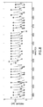
- FIG. 7 illustrates an example chart of pressure measurements over four medication delivery intervals
- FIGS. 8 and 9 illustrate data comparing pulses to provide an indication of flow status of the fluid path using the example process described in FIG. 5 ;
- FIG. 10 illustrates data comparing peak pressure data within the peripheral IV catheter recorded during an IV infusion according to an exemplary embodiment of the invention
- FIG. 12 illustrates another flowchart of an example process that the medication system may implement in accordance with an exemplary embodiment of the present invention.
- FIG. 1 illustrates an example medication delivery system 100 that detects partial or complete occlusions during delivery of medication fluid to a patient or sampling or withdrawal of fluid from a patient.
- the medication delivery system 100 generally operates by delivering minute boluses (such as 0.5 microliters) to a patient over a short pulse (such as 100 milliseconds, 1 second, and so on) at regular intervals (such as a period of 3 minutes, or the like).
- the medication delivery system 100 includes a pump controller 105 that delivers a pulse of medication fluid to a patient via a fluid path such as tubing 110 .
- the pump controller 105 includes a fluid reservoir 115 containing the medication fluid.
- the medication delivery system 100 includes a fluid detector 125 that receives and measures characteristics of the pressure pulse in the medication fluid to determine if it is flowing in the medication delivery system 100 and being delivered to the patient.
- the fluid detector 125 is placed inline with tubing 110 and in proximity with an infusion set hub 130 containing an infusion cannula that delivers the medication fluid into the patient.
- the fluid detector 125 receives the medication fluid and measures any suitable characteristic of the fluid such as pressure, temperature, force, flow rate, volume, conductance, resistance and so forth. The fluid detector 125 then communicates the measurement results to the pump controller 105 , which uses the fluid measurements to determine if the medication fluid is sufficiently flowing in the fluid path and being delivered to the patient. In one example, the fluid detector 125 may transmit the fluid measurements to the pump controller 105 via a wireless interface. In other examples, the fluid detector 125 may transmit the measurements via a wired interface, such as an electrical conductor embedded in the tubing 110 , or the like.
- FIG. 2 illustrates a block diagram of an example pump controller 105 that controls the operation of the medication delivery system 100 by receiving the measurements from the fluid detector 125 shown in FIG. 1 .
- a processor 200 receives the fluid measurements via any suitable interface, such as an analog-to-digital converter, a modulated input, or the like.
- the fluid measurements are stored in a memory 210 which can be separate or integral with the processor 205 .
- the processor 205 determines if an occlusion has occurred and generates an output via output interface 215 to provide notice of the occlusion.
- the output interface 215 is generally any output mechanism that displays a warning to a health care professional or patient to provide notice of an occlusion.
- the pump controller 105 may include a liquid crystal display (LCD) that outputs pressure measurements to the health care professional and, in the event an occlusion is determined to be occurring, can output a display indicator on the LCD to provide such notice.
- LCD liquid crystal display
- a light emitting diode (LED) may be activated or modulated, an audible event such as an alarm may be output, or a haptic event such as a vibration via a vibration motor (not shown) via the output interface 215 .
- the pump controller also includes a servo controller 230 for actuating a servo motor 235 for driving the piston 120 to cause fluid to flow from the fluid reservoir 115 .
- the servo controller 230 may be integral with processor 200 .
- the pump controller 105 may also include a servo sensor 240 to detect pressure applied to the piston during piston 120 movement during medication delivery.
- FIG. 3 is a perspective view of an exemplary in-line fluid detector 125 that is potentially implemented via a standard inline medical connector such as a Luer-Lok®, Safety-Lok®, or any other suitable connector. That is, the fluid detector 125 includes a female connector 302 disposed at a proximal end and a male connector 304 disposed at a distal end to allow the fluid detector 125 to be connected inline between the tubing 110 and the infusion set 130 .
- the fluid detector 125 includes a mechanical housing 306 disposed between the female connector 302 and male connector 302 and includes a fluid path 308 to permit fluid flow and to detect a property of the flowing fluid, such as the pressure of the fluid.
- the fluid path 308 includes a sensor 310 that detects a suitable characteristic of the fluid such as pressure.
- the pressure may be measured in conjunction with other characteristics to improve fluid detection, such as temperature, viscosity, or any other suitable characteristic.
- the sensor 310 is substantially encapsulated by a shield 312 , preferably constructed of a polymer, or the like, to physically isolate the sensor 310 from the fluid path and prevent any contact with the medication fluid.
- the sensor 310 may directly contact the medication fluid.
- the sensor 310 is a strain gauge that detects pressure of the medication fluid in the fluid path 308 .
- the fluid detector 125 may be integrated within the infusion set hub, thereby detecting flow of the medication fluid at the location of delivery to a patient.
- the fluid detector 125 may include a standard or proprietary connector adapted to receive both medication fluid and electrical signals in a single integral connector.
- the fluid detector 125 may be adapted to send the measurement data as electrical data via tubing 110 having electrically conductive members therein that are isolated from the fluid path. Further, such electrical signals provided via the conductive members may be configured such that medication fluids are not affected by the data transmission.
- the medication fluid is preferably isolated from electromagnetic fields, and the like.
- FIG. 4 illustrates an example block diagram of a fluid detector 125 disposed in the mechanical housing 306 and detects characteristics of the fluid in fluid path 308 as described in detail above.
- the fluid detector 125 includes a processor 400 that is implemented by any suitable device for detecting the measurements of the sensor 310 and providing the results to the pump controller 105 , such as a logic circuit, an ASIC, an FPGA, a microcontroller, a microprocessor, or the like. That is, the sensor 310 is coupled to an input on the processor 400 .
- a highly integrated processing device such as a microcontroller having an integrated analog-to-digital converter and memory is preferred due to advantageous size and power characteristics.
- the processor 400 is configured to receive power from an power source 405 of the fluid detector 125 that may be integral or extrinsic.
- the integral power source 405 may be provided via inductive coupling to an inductor that receives wireless signals and converts the magnetic field into electric power.
- the fluid detector 125 also preferably includes a RF transceiver 410 that sends and receives data via antenna 415 .
- the fluid detector 125 may receive an instruction to measure the fluid pressure via a wireless transmission from the pump controller 105 .
- the processor 400 may induce the sensor 310 to provide a measurement on at least one input. For example, in the event the sensor 310 is implemented via a strain gauge in the fluid path 308 , a first voltage is applied to the sensor 400 via an output of processor 400 . An input of processor 400 receives second voltage that is reduced via the electrical resistance of the strain gauge and calculates the strain pressure applied to the sensor 310 .
- an in-line pressure sensor directly measures fluid pressure, as opposed to a force measurement device coupled to a piston 120 within a reservoir 115 , eliminating the sometimes dominating force components contributed by static and dynamic friction, and the like, associated with the piston.
- FIG. 5 illustrates an example process 500 for detecting occlusion in the medication delivery system during treatment of a patient.
- a medication delivery interval begins with a delivery of a dose of the medication fluid and continues until the next medication delivery occurs.
- the example process 500 and the medication delivery interval begin by delivering a dose of medication fluid at step 505 .
- the pump controller transmits a signal to initiate a pressure measurement in the fluid path at step 510 .
- the fluid detector measures the fluid pressure in the fluid path and transmits the pressure measurement to the pump controller, which stores the pressure measurement at step 515 .
- the example process 500 determines if the current medication delivery interval has expired at step 520 . If the current medication delivery interval has not expired at step 520 , the example process 500 returns to step 510 to transmit a signal to initiate and receive the next pressure measurement in the current medication delivery interval.
- the example process 500 determines if an occlusion occurred during the current medication delivery interval occurred at step 525 . If an occlusion did not occur at step 525 , the example process 500 returns to step 505 to initiate a next medication delivery interval that begins with delivering a next dose of the medication fluid.
- the example process 500 may determine if there should be an attempt to resolve the occlusion based on any suitable criteria at step 530 . For example, if the maximum pressure exceeds a predefined pressure during a single medication delivery interval, the example process 500 may determine it should attempt to resolve the occlusion at step 535 . For example, the example process 500 may generate a very large transient pressure peak by actuating the piston and increasing the rate at which the piston moves. Alternatively, an increased amount of medication fluid is delivered to the patient and the pressures of the medication fluid are measured at various times and then compared after a period of time.
- a drug-free fluid connected to the fluid path as close as possible to the infusion set, which may be delivered such that the drug-free fluid passes through the infusion set and through the delivery location of the patient.
- this medication clearing event could be accompanied by or preceded by a small movement of the piston in the negative direction, that is, increasing the volume in the fluid reservoir such that pressure is normalized, thereby preventing over-medicating the patient.
- the infusion set may be manipulated by a high frequency displacement of the infusion set tip by, for example, motion of a piezoelectric device located in the infusion set body or by manual manipulation by the patient or medical professional.
- the example process 500 at steps 530 - 545 waits until the occlusion is resolved before continuing medication delivery.
- the example process 500 would continue to compare the pressure measurements with previous pressure measurements prior to the occlusion event to ensure correct delivery of medication.
- the example process 500 may flush the previous pressure measurements based on a change in the system that does not substantially affect delivery of the medication, such as a partial occlusion due to the configuration of the fluid path, such as tangling in clothing, for example.
- One example implementation of the example process 500 may be a drug delivery feedback system implementing an artificial pancreas.
- knowledge of insulin delivery status will improve delivery of insulin to the patient using real-time insulin delivery data based on the pressure measurements at the fluid detector.
- the example process 500 uses previous insulin delivery volumes to calculate the preferred delivery volume of medication for the patient at any time.
- data regarding incomplete or missing delivery of the insulin would improve performance of such an example system.
- the example process 500 may be adapted to detect occlusions during medication delivery intervals. For instance, if the peak pressure or the minimum pressure of the fluid exceeds a predefined threshold, the example process 500 may determine that an occlusion has occurred in the current medication delivery interval. Further, if a subsequent peak pressure is greater than a previous peak pressure by a predefined threshold, the example process 500 may generate an alarm and halt further delivery of the medication fluid before the medication delivery interval expires.
- the minimum pressure P MIN is filtered and/or averaged over several delivery pulses to remove noise in the measurements.
- an occlusion may be recognized by subsequent P MIN measurements increasing in magnitude, indicating increasing pressure due to multiple delivery pulses failing due to the occlusion and causing fluid pressure to rise.
- the example process 600 calculates a weighted pressure P WEIGHT from a previous medication delivery interval.
- weighted pressure P WEIGHT W*P MAX +(1 ⁇ W)*P MIN
- W is a weighting factor, such as 0.25, that determines the sensitivity of the occlusion detection
- P MAX is the maximum pressure from a previous medication delivery interval
- P MIN is the minimum pressure from the previous medication delivery interval.
- the previous medication delivery interval is two intervals before the current medication delivery interval.
- multiple previous medication delivery intervals may be used to generate the weighted pressure P WEIGHT in any suitable fashion, that is, by multiple comparisons, averaging the measurements, generating a detection window that adjusts based on the magnitude of the maximum pressure, and so forth.
- the sensitivity may be variably adjusted based on suitable factors to ensure accurate detection of occlusions. For example, if the minimum pressure P MIN is sufficiently low due to the viscosity of the liquid and the maximum pressure P MAX is large, the sensitivity can be increased by adjusting the weighting factor W to account for more subtle changes in the minimum pressure P MIN .
- the method is not limited to analyzing a set of consecutive intervals indicating a problematic flow state. That is, the method should be understood to include embodiments that can accommodate intervening intervals indicating successful flow.
- the example process 600 After calculating the weighted pressure P WEIGHT , the example process 600 compares the current minimum pressure to a predetermined threshold pressure P THRESH (e.g., 3 psi) at step 615 . In the event that the minimum pressure exceeds the threshold pressure P THRESH , the example process 600 determines that an occlusion is occurring at step 620 and exits. If the minimum pressure does not exceed the threshold pressure P THRESH , the current minimum pressure is compared to the weighted pressure P WEIGHT at step 625 . If the current minimum pressure exceeds the weighted pressure P WEIGHT , the example process 600 determines that an occlusion is occurring at step 620 and the example process 600 ends. However, if the current minimum pressure does not exceed the weighted pressure P WEIGHT , the example process 600 determines that an occlusion is not occurring at step 630 and the example process 600 ends.
- P THRESH e.g. 3 psi
- another exemplary method of determining if an occlusion has occurred during the medication delivery interval may be performed by observing large fluctuations.
- the method compares the current pressure profile to a smoothed profile, such as a smoothing spline fit, and tracks measurement events that deviate significantly from the smoothed curve.
- a smoothed profile such as a smoothing spline fit
- flow of the medication of fluid is determined to be unsuccessful if the measured pressure exceeds two standard deviations for a suitable period of time, such as 3 minutes.
- the medication delivery system 100 actuates the piston 120 to force medication in a fluid reservoir 115 to be delivered to the patient.
- the pressure increases in the tubing 100 and traverses toward the delivery location of the medication.
- measurement 704 illustrates that the pressure increases at the fluid detector 125 during the initial delivery of the medication and, therefore, the maximum pressure 704 (P MAX ) occurs at the beginning of medication delivery period 702 .
- the medication delivery system is configured to record the actual maximum pressure that occurs in the fluid path. In some examples, the medication delivery system 100 may begin recording pressure data before the expected maximum pressure occurs at the fluid detector.
- the pressure decays at the fluid detector 125 after delivery of the medication in a decay region and returns to an equilibrium region where a minimum pressure P MIN 706 of the medication delivery period is determined.
- a minimum pressure occurs in the latter portion of the medication delivery interval 702 .
- the weighted pressure 708 can be determined using the maximum pressure 704 , minimum pressure 706 , and a weighting factor (e.g., 0.25) as described above.
- the maximum pressure 714 is substantially equal to the maximum pressure 704 and the minimum pressure 716 is substantially equal to the minimum pressure 706 .
- no occlusion is detected in the second medication delivery interval 712 based on the weighted pressure 708 of the first medication delivery interval because the minimum pressure 716 does not exceed the weighted pressure 708 of the first medication delivery interval 702 .
- the maximum pressure 724 is substantially equal to the maximum pressure 704 .
- the minimum pressure 726 increases substantially such that it exceeds the weighted pressures 708 and 718 of the previous medication delivery intervals 702 and 712 . That is, the example process 600 would detect an occlusion in the third medication delivery interval 722 because the minimum pressure 726 exceeds at least one of the weighted pressures 708 and 718 .
- the example process 600 uses any suitable weighted pressure to detect an occlusion in the current medication delivery interval.
- FIGS. 8-9 illustrate data from a clinical trial of an example medication delivery system 100 to evaluate efficiency of basal/bolus infusion from commercial infusion pumps.
- a patient was fitted with infusion sets having a sensor 310 to measure pressure to determine occlusions.
- pressure data was measured at a rate of 1 Hz and fixed amounts of medication were delivered in 3 minute intervals.
- the pressure data was analyzed by removing noise and spurious measurements, identification of minimum and maximum measure pressures, and flow was determined. For example, to capture the first peak, a second derivative of the pressure was calculated from the data illustrated in FIG. 8 and the minimum value within 160 seconds of the maximum pressure. The minimum values after the 160 second window were also recorded for further evaluation as illustrated in FIG. 8 .
- the delivery status for each pulse was determined by comparing the weighted average of the maximum and minimum pressure of the second prior pulse as described above.
- a threshold pressure of 3 psi was set to indicate that an occlusion has occurred in the flow path.
- a delivery factor indicates the number of medication boluses delivered in an interval. Thus, if medication fluid was flowing, the delivery factor would be 1.
- the medication delivery system 100 may also determine the number of medication intervals delivered to the user based on previously detected occlusions. As illustrated in FIG. 9 , the medication delivery system 100 determines successful delivery of medication at point A. However, using the measured data at point B, determines that an occlusion is occurring, thereby having a delivery factor of zero. As further illustrated in FIG. 9 , however, temporary occlusions may work themselves out. One such temporary occlusion is illustrated by the pressure over-time-curve s just past point B of FIG. 9 . As shown, pressure increased with each pulse before, during, and after point B, but then pressure normalized, indicating that the temporary occlusion was resolved.
- the medication delivery system described herein is sensitive to both low pressure and high pressure by eliminating the impact of potential forces experienced by the piston on detection sensitivity and relying on the pressure in the fluid path.
- FIG. 11 illustrates a molded needle hub 1105 that is fastened to a needle barrel 1110 to form a syringe 1115 and is configured to communication with a fluid feedback device.
- the molded needle hub 1105 includes a fluid detector 125 integral therein to detect any suitable fluid characteristic such as pressure, force, and so forth.
- the fluid detector 125 includes a sensor for sensing the fluid characteristic and further devices to enable to communication with the fluid feedback device, which displays the fluid characteristic.
- the fluid feedback device is configured to receive information from the fluid detector 125 , process the information to determine if a flow deviation is occurring that could affect the treatment of the patient and provide an indication if a flow deviation is occurring.
- the fluid feedback device may be configured to stop the medical fluid communication, such as an IV delivery system for example.
- the fluid feedback device determines that there is a flow deviation that may affect the patient, the fluid feedback device provides an alarm to indicate that the flow deviation exists.
- the fluid feedback device may be implemented via a touch-sensitive tablet computer that executes an application to display the processed feedback information, however any suitable device could be used, including a tablet computer, a personal computer, a proprietary device for displaying the received information, or the like.
- FIG. 12 illustrates an example process 1200 to detect a flow deviation in any suitable medical fluid communication system.
- the example process 1200 begins with the communication of a medical fluid, such as blood, urine, antibiotics, glucose, electrolytic solutions, and so on, at step 1205 .
- the fluid feedback device transmits an instruction to the fluid detector 125 to begin measuring the fluid and begins receiving measurements from the fluid detector at step 1215 .
- the example process 1200 determines if a flow deviation is occurring at step 1220 .
- the example process 1200 may implement the process 600 discussed in connection with FIG. 6 to detect a flow deviation.
- the flow deviation at step 1220 could be determined by comparing the received measurement to a static or dynamic threshold.
- a weighted average may be computed using a decaying average and compared to a threshold or a first and/or second derivative of the previous data and compared to a threshold.
- the example process 1200 generates an alarm to indicate that a flow deviation is occurring at step 1225 .
- the medical fluid communication may be discontinued at step 1225 .
- the example process 1200 determines if medication delivery continues at step 1230 . If the medical fluid communication continues, the example process returns to step 1215 to continue measuring and monitoring the flow of the medication fluid. If the medication delivery has ended at step 1230 , the example process ends.
- timed or scheduled replacement of PIVC catheters may be removed prematurely, thereby increasing the cost of medical treatment.
- the examples described above allow the medical fluid communication system to detect and provide an indication that a flow deviation occurs and, as such, the PIVC catheter should be replaced to ensure proper communication of medical fluids with the patient.
- a temperature sensor and a pressure sensor may be used in conjunction because temperature and pressure are correlated. Generally, it may be beneficial to measure the temperature in the fluid path in the event that the temperature of the medication fluctuates, thereby allowing temperature compensation to facilitate the detection of occlusions.
- a force sensor may be implemented outside the fluid path such as, for example, a drive mechanism that connects a servo motor to the piston.
- a fluid volume sensor may be implemented to detect the volume of fluid passing in the fluid path.
Priority Applications (2)
| Application Number | Priority Date | Filing Date | Title |
|---|---|---|---|
| US14/050,207 US9480794B2 (en) | 2012-10-12 | 2013-10-09 | System and method for detecting occlusions in a medication infusion system using pulsewise pressure signals |
| US15/296,773 US9775947B2 (en) | 2012-10-12 | 2016-10-18 | System and method for detecting occlusions in a medication infusion system using pulsewise pressure signals |
Applications Claiming Priority (2)
| Application Number | Priority Date | Filing Date | Title |
|---|---|---|---|
| US201261713096P | 2012-10-12 | 2012-10-12 | |
| US14/050,207 US9480794B2 (en) | 2012-10-12 | 2013-10-09 | System and method for detecting occlusions in a medication infusion system using pulsewise pressure signals |
Related Child Applications (1)
| Application Number | Title | Priority Date | Filing Date |
|---|---|---|---|
| US15/296,773 Division US9775947B2 (en) | 2012-10-12 | 2016-10-18 | System and method for detecting occlusions in a medication infusion system using pulsewise pressure signals |
Publications (2)
| Publication Number | Publication Date |
|---|---|
| US20140107613A1 US20140107613A1 (en) | 2014-04-17 |
| US9480794B2 true US9480794B2 (en) | 2016-11-01 |
Family
ID=50476029
Family Applications (2)
| Application Number | Title | Priority Date | Filing Date |
|---|---|---|---|
| US14/050,207 Active US9480794B2 (en) | 2012-10-12 | 2013-10-09 | System and method for detecting occlusions in a medication infusion system using pulsewise pressure signals |
| US15/296,773 Active US9775947B2 (en) | 2012-10-12 | 2016-10-18 | System and method for detecting occlusions in a medication infusion system using pulsewise pressure signals |
Family Applications After (1)
| Application Number | Title | Priority Date | Filing Date |
|---|---|---|---|
| US15/296,773 Active US9775947B2 (en) | 2012-10-12 | 2016-10-18 | System and method for detecting occlusions in a medication infusion system using pulsewise pressure signals |
Country Status (7)
| Country | Link |
|---|---|
| US (2) | US9480794B2 (es) |
| EP (2) | EP2906283B1 (es) |
| JP (1) | JP6525879B2 (es) |
| CN (1) | CN205041960U (es) |
| CA (1) | CA2887504C (es) |
| ES (2) | ES2823499T3 (es) |
| WO (1) | WO2014059006A1 (es) |
Cited By (9)
| Publication number | Priority date | Publication date | Assignee | Title |
|---|---|---|---|---|
| US10674950B2 (en) | 2011-04-26 | 2020-06-09 | Velano Vascular, Inc. | Systems and methods for phlebotomy through a peripheral IV catheter |
| US10773056B2 (en) | 2017-03-21 | 2020-09-15 | Velano Vascular, Inc. | Systems and methods for controlling catheter device size |
| US11090461B2 (en) | 2017-03-21 | 2021-08-17 | Velano Vascular, Inc. | Devices and methods for fluid transfer through a placed peripheral intravenous catheter |
| US11191897B2 (en) | 2019-03-04 | 2021-12-07 | Eitan Medical Ltd. | In cycle pressure measurement |
| US11207498B2 (en) | 2019-08-20 | 2021-12-28 | Velano Vascular, Inc. | Fluid transfer devices with extended length catheters and methods of using the same |
| US11331023B2 (en) | 2011-04-26 | 2022-05-17 | Velano Vascular, Inc. | Systems and methods for phlebotomy through a peripheral IV catheter |
| WO2022132554A1 (en) * | 2020-12-15 | 2022-06-23 | Becton, Dickinson And Company | Apparatuses and methods for pausing an infusion pump during a dispense stroke to improve occlusion sensing |
| US11389624B2 (en) | 2020-11-26 | 2022-07-19 | Avia Vascular, Llc | Blood collection devices, systems, and methods |
| US11890451B2 (en) | 2019-03-05 | 2024-02-06 | Eitan Medical Ltd. | Anti-free-flow valve |
Families Citing this family (7)
| Publication number | Priority date | Publication date | Assignee | Title |
|---|---|---|---|---|
| US10842931B2 (en) | 2012-12-17 | 2020-11-24 | Board Of Regents Of The University Of Texas System | System of intravenous fluid/medication delivery that employs signature flow amplitudes of frequencies to facilitate the detection of intravenous infiltration |
| EP3804777B1 (en) | 2013-12-18 | 2023-01-25 | 3M Innovative Properties Co. | System for providing reduced-pressure therapy and instillation therapy |
| WO2017008960A1 (en) * | 2015-07-10 | 2017-01-19 | Fresenius Vial Sas | Method and device for detecting an occlusion in an infusion line |
| EP3162400A1 (en) * | 2015-11-02 | 2017-05-03 | Sanofi | Needle assembly |
| CN105726067B (zh) * | 2016-01-15 | 2018-08-07 | 刘艳 | 一种妇产科检查智能给药取样一体装置 |
| EP3710080B1 (en) * | 2017-11-16 | 2024-04-24 | Fresenius Vial SAS | Infusion device and method for administering a medical fluid to a patient |
| EP3843825A4 (en) * | 2018-08-28 | 2022-05-25 | Bayer HealthCare, LLC | USING PRESSURE MEASUREMENTS TO DETECT REUSE OF PATIENT LINES |
Citations (15)
| Publication number | Priority date | Publication date | Assignee | Title |
|---|---|---|---|---|
| US4534756A (en) * | 1983-04-11 | 1985-08-13 | Ivac Corporation | Fault detection apparatus and method for parenteral infusion system |
| US5096385A (en) | 1989-11-08 | 1992-03-17 | Ivac Corporation | Method and system for upstream occlusion detection |
| US5800387A (en) | 1996-10-04 | 1998-09-01 | Alaris Medical Systems, Inc. | Safety monitoring apparatus for a patient care system |
| US6656148B2 (en) | 1999-06-18 | 2003-12-02 | Animas Corporation | Infusion pump with a sealed drive mechanism and improved method of occlusion detection |
| US20040127844A1 (en) * | 2002-03-01 | 2004-07-01 | Flaherty J. Christopher | Flow condition sensor assembly for patient infusion device |
| US7621893B2 (en) | 1998-10-29 | 2009-11-24 | Medtronic Minimed, Inc. | Methods and apparatuses for detecting occlusions in an ambulatory infusion pump |
| WO2010046728A1 (en) | 2008-10-22 | 2010-04-29 | Debiotech S.A. | Mems fluid pump with integrated pressure sensor for dysfunction detection |
| US7726328B2 (en) | 2003-03-04 | 2010-06-01 | Wolfe Tory Medical, Inc. | Medical valve and method to monitor intra-abdominal pressure |
| US20100168607A1 (en) | 2003-10-02 | 2010-07-01 | Medtronic, Inc. | Determining catheter status |
| US7828528B2 (en) | 2007-09-06 | 2010-11-09 | Asante Solutions, Inc. | Occlusion sensing system for infusion pumps |
| US7938797B2 (en) | 2008-05-05 | 2011-05-10 | Asante Solutions, Inc. | Infusion pump system |
| US8007460B2 (en) * | 2004-09-09 | 2011-08-30 | Plc Medical Systems, Inc. | Patient hydration system and method |
| US8081069B2 (en) | 2006-02-13 | 2011-12-20 | Roche Diagnostics International Ag | Method and device for identifying a change in pressure in the liquid path of a microdosing device |
| US8267893B2 (en) | 1998-10-29 | 2012-09-18 | Medtronic Minimed, Inc. | Method and apparatus for detecting occlusions in an ambulatory infusion pump |
| US8568349B2 (en) | 2008-08-27 | 2013-10-29 | Roche Diagnostics International Ag | Flow control valves for leakage detection, free-flow prevention and occlusion detection |
-
2013
- 2013-10-09 CA CA2887504A patent/CA2887504C/en active Active
- 2013-10-09 EP EP13845914.4A patent/EP2906283B1/en active Active
- 2013-10-09 WO PCT/US2013/064113 patent/WO2014059006A1/en active Application Filing
- 2013-10-09 ES ES18167682T patent/ES2823499T3/es active Active
- 2013-10-09 CN CN201390000888.8U patent/CN205041960U/zh not_active Expired - Lifetime
- 2013-10-09 JP JP2015536862A patent/JP6525879B2/ja active Active
- 2013-10-09 US US14/050,207 patent/US9480794B2/en active Active
- 2013-10-09 ES ES13845914.4T patent/ES2675788T3/es active Active
- 2013-10-09 EP EP18167682.6A patent/EP3369454B1/en active Active
-
2016
- 2016-10-18 US US15/296,773 patent/US9775947B2/en active Active
Patent Citations (15)
| Publication number | Priority date | Publication date | Assignee | Title |
|---|---|---|---|---|
| US4534756A (en) * | 1983-04-11 | 1985-08-13 | Ivac Corporation | Fault detection apparatus and method for parenteral infusion system |
| US5096385A (en) | 1989-11-08 | 1992-03-17 | Ivac Corporation | Method and system for upstream occlusion detection |
| US5800387A (en) | 1996-10-04 | 1998-09-01 | Alaris Medical Systems, Inc. | Safety monitoring apparatus for a patient care system |
| US7621893B2 (en) | 1998-10-29 | 2009-11-24 | Medtronic Minimed, Inc. | Methods and apparatuses for detecting occlusions in an ambulatory infusion pump |
| US8267893B2 (en) | 1998-10-29 | 2012-09-18 | Medtronic Minimed, Inc. | Method and apparatus for detecting occlusions in an ambulatory infusion pump |
| US6656148B2 (en) | 1999-06-18 | 2003-12-02 | Animas Corporation | Infusion pump with a sealed drive mechanism and improved method of occlusion detection |
| US20040127844A1 (en) * | 2002-03-01 | 2004-07-01 | Flaherty J. Christopher | Flow condition sensor assembly for patient infusion device |
| US7726328B2 (en) | 2003-03-04 | 2010-06-01 | Wolfe Tory Medical, Inc. | Medical valve and method to monitor intra-abdominal pressure |
| US20100168607A1 (en) | 2003-10-02 | 2010-07-01 | Medtronic, Inc. | Determining catheter status |
| US8007460B2 (en) * | 2004-09-09 | 2011-08-30 | Plc Medical Systems, Inc. | Patient hydration system and method |
| US8081069B2 (en) | 2006-02-13 | 2011-12-20 | Roche Diagnostics International Ag | Method and device for identifying a change in pressure in the liquid path of a microdosing device |
| US7828528B2 (en) | 2007-09-06 | 2010-11-09 | Asante Solutions, Inc. | Occlusion sensing system for infusion pumps |
| US7938797B2 (en) | 2008-05-05 | 2011-05-10 | Asante Solutions, Inc. | Infusion pump system |
| US8568349B2 (en) | 2008-08-27 | 2013-10-29 | Roche Diagnostics International Ag | Flow control valves for leakage detection, free-flow prevention and occlusion detection |
| WO2010046728A1 (en) | 2008-10-22 | 2010-04-29 | Debiotech S.A. | Mems fluid pump with integrated pressure sensor for dysfunction detection |
Cited By (17)
| Publication number | Priority date | Publication date | Assignee | Title |
|---|---|---|---|---|
| US11331023B2 (en) | 2011-04-26 | 2022-05-17 | Velano Vascular, Inc. | Systems and methods for phlebotomy through a peripheral IV catheter |
| US10729367B1 (en) | 2011-04-26 | 2020-08-04 | Velano Vascular, Inc. | Systems and methods for phlebotomy through a peripheral IV catheter |
| US11957466B2 (en) | 2011-04-26 | 2024-04-16 | Velano Vascular, Inc. | Systems and methods for phlebotomy through a peripheral IV catheter |
| US10799167B1 (en) | 2011-04-26 | 2020-10-13 | Velano Vascular, Inc. | Systems and methods for phlebotomy through a peripheral IV catheter |
| US10674950B2 (en) | 2011-04-26 | 2020-06-09 | Velano Vascular, Inc. | Systems and methods for phlebotomy through a peripheral IV catheter |
| US11351340B2 (en) | 2017-03-21 | 2022-06-07 | Velano Vascular, Inc. | Systems and methods for controlling catheter device size |
| US11090461B2 (en) | 2017-03-21 | 2021-08-17 | Velano Vascular, Inc. | Devices and methods for fluid transfer through a placed peripheral intravenous catheter |
| US11583661B2 (en) | 2017-03-21 | 2023-02-21 | Velano Vascular, Inc. | Devices and methods for fluid transfer through a placed peripheral intravenous catheter |
| US11744990B2 (en) | 2017-03-21 | 2023-09-05 | Velano Vascular, Inc. | Systems and methods for controlling catheter device size |
| US10773056B2 (en) | 2017-03-21 | 2020-09-15 | Velano Vascular, Inc. | Systems and methods for controlling catheter device size |
| US11191897B2 (en) | 2019-03-04 | 2021-12-07 | Eitan Medical Ltd. | In cycle pressure measurement |
| US11890451B2 (en) | 2019-03-05 | 2024-02-06 | Eitan Medical Ltd. | Anti-free-flow valve |
| US11207498B2 (en) | 2019-08-20 | 2021-12-28 | Velano Vascular, Inc. | Fluid transfer devices with extended length catheters and methods of using the same |
| US11389624B2 (en) | 2020-11-26 | 2022-07-19 | Avia Vascular, Llc | Blood collection devices, systems, and methods |
| US11452847B1 (en) | 2020-11-26 | 2022-09-27 | Avia Vascular, Llc | Blood collection devices, systems, and methods |
| US11638806B2 (en) | 2020-11-26 | 2023-05-02 | Avia Vascular, Llc | Blood collection devices, systems, and methods |
| WO2022132554A1 (en) * | 2020-12-15 | 2022-06-23 | Becton, Dickinson And Company | Apparatuses and methods for pausing an infusion pump during a dispense stroke to improve occlusion sensing |
Also Published As
| Publication number | Publication date |
|---|---|
| CA2887504C (en) | 2021-05-25 |
| US20140107613A1 (en) | 2014-04-17 |
| EP2906283A1 (en) | 2015-08-19 |
| US20170035965A1 (en) | 2017-02-09 |
| WO2014059006A8 (en) | 2014-10-09 |
| ES2823499T3 (es) | 2021-05-07 |
| EP2906283B1 (en) | 2018-04-18 |
| ES2675788T3 (es) | 2018-07-12 |
| JP2015533096A (ja) | 2015-11-19 |
| CN205041960U (zh) | 2016-02-24 |
| EP2906283A4 (en) | 2016-06-29 |
| US9775947B2 (en) | 2017-10-03 |
| EP3369454B1 (en) | 2020-07-15 |
| EP3369454A1 (en) | 2018-09-05 |
| JP6525879B2 (ja) | 2019-06-05 |
| WO2014059006A1 (en) | 2014-04-17 |
| CA2887504A1 (en) | 2014-04-17 |
Similar Documents
| Publication | Publication Date | Title |
|---|---|---|
| US9775947B2 (en) | System and method for detecting occlusions in a medication infusion system using pulsewise pressure signals | |
| US5190522A (en) | Device for monitoring the operation of a delivery system and the method of use thereof | |
| US8264363B2 (en) | System and method for detecting occlusion using flow sensor output | |
| JP2019051389A (ja) | 注入デバイス用高性能アダプタ | |
| US9833561B2 (en) | Occlusion detection in delivery of fluids | |
| JPH0561950B2 (es) | ||
| US11033681B2 (en) | Automatic catheter recognition and associated methods, systems and circuits | |
| US20220387709A1 (en) | Systems and methods for compensation of tubing stress relaxation effects with infusion pump systems | |
| JP7161023B2 (ja) | 薬物送達システムおよび薬物送達システムを動作させる方法 | |
| CN116785533A (zh) | 一种针头脱落的检测方法与系统 |
Legal Events
| Date | Code | Title | Description |
|---|---|---|---|
| AS | Assignment |
Owner name: BECTON, DICKINSON AND COMPANY, NEW JERSEY Free format text: ASSIGNMENT OF ASSIGNORS INTEREST;ASSIGNORS:KEITH, STEVEN;MCVEY, ELAINE;TONG, FRANCES;AND OTHERS;SIGNING DATES FROM 20140110 TO 20140114;REEL/FRAME:032042/0771 |
|
| STCF | Information on status: patent grant |
Free format text: PATENTED CASE |
|
| MAFP | Maintenance fee payment |
Free format text: PAYMENT OF MAINTENANCE FEE, 4TH YEAR, LARGE ENTITY (ORIGINAL EVENT CODE: M1551); ENTITY STATUS OF PATENT OWNER: LARGE ENTITY Year of fee payment: 4 |