US9479232B1 - Method of achieving ultra-wideband true-time-delay beam steering for active electronically scanned arrays - Google Patents
Method of achieving ultra-wideband true-time-delay beam steering for active electronically scanned arrays Download PDFInfo
- Publication number
- US9479232B1 US9479232B1 US14/826,153 US201514826153A US9479232B1 US 9479232 B1 US9479232 B1 US 9479232B1 US 201514826153 A US201514826153 A US 201514826153A US 9479232 B1 US9479232 B1 US 9479232B1
- Authority
- US
- United States
- Prior art keywords
- signal
- phase
- timing
- antenna
- mixer
- Prior art date
- Legal status (The legal status is an assumption and is not a legal conclusion. Google has not performed a legal analysis and makes no representation as to the accuracy of the status listed.)
- Active
Links
Images


Classifications
-
- H—ELECTRICITY
- H04—ELECTRIC COMMUNICATION TECHNIQUE
- H04B—TRANSMISSION
- H04B7/00—Radio transmission systems, i.e. using radiation field
- H04B7/02—Diversity systems; Multi-antenna system, i.e. transmission or reception using multiple antennas
- H04B7/04—Diversity systems; Multi-antenna system, i.e. transmission or reception using multiple antennas using two or more spaced independent antennas
- H04B7/06—Diversity systems; Multi-antenna system, i.e. transmission or reception using multiple antennas using two or more spaced independent antennas at the transmitting station
- H04B7/0613—Diversity systems; Multi-antenna system, i.e. transmission or reception using multiple antennas using two or more spaced independent antennas at the transmitting station using simultaneous transmission
- H04B7/0615—Diversity systems; Multi-antenna system, i.e. transmission or reception using multiple antennas using two or more spaced independent antennas at the transmitting station using simultaneous transmission of weighted versions of same signal
- H04B7/0617—Diversity systems; Multi-antenna system, i.e. transmission or reception using multiple antennas using two or more spaced independent antennas at the transmitting station using simultaneous transmission of weighted versions of same signal for beam forming
-
- H—ELECTRICITY
- H04—ELECTRIC COMMUNICATION TECHNIQUE
- H04B—TRANSMISSION
- H04B7/00—Radio transmission systems, i.e. using radiation field
- H04B7/02—Diversity systems; Multi-antenna system, i.e. transmission or reception using multiple antennas
- H04B7/04—Diversity systems; Multi-antenna system, i.e. transmission or reception using multiple antennas using two or more spaced independent antennas
- H04B7/0408—Diversity systems; Multi-antenna system, i.e. transmission or reception using multiple antennas using two or more spaced independent antennas using two or more beams, i.e. beam diversity
-
- H—ELECTRICITY
- H04—ELECTRIC COMMUNICATION TECHNIQUE
- H04L—TRANSMISSION OF DIGITAL INFORMATION, e.g. TELEGRAPHIC COMMUNICATION
- H04L27/00—Modulated-carrier systems
- H04L27/26—Systems using multi-frequency codes
- H04L27/2601—Multicarrier modulation systems
- H04L27/2626—Arrangements specific to the transmitter only
- H04L27/2646—Arrangements specific to the transmitter only using feedback from receiver for adjusting OFDM transmission parameters, e.g. transmission timing or guard interval length
Definitions
- ESA electronically steered array
- Various embodiments are presented herein relating to beam steering an array antenna by modifying an intermediate frequency (IF) signal(s) (or waveform(s)) prior to conversion to RF signal(s).
- IF intermediate frequency
- digital components e.g., having low cost, can be utilized to achieve array antenna beam steering, whereby the beam steering can be achieved with high bandwidth.
- the antenna array comprises a plurality of antenna elements, each of which is energized by way of a respective channel. Accordingly, the antenna array includes multiple channels. Further, the antenna array comprises mixers respectively positioned on the channels, wherein the mixers are generally configured to convert IF signals to RF signals, and vice-versa.
- an arbitrary waveform generator can be utilized to generate a plurality of IF signals.
- the AWG can utilize direct digital synthesis (DDS) during generation of each of the IF signals in the plurality of IF signals.
- DDS can facilitate generation of a first IF signal having a different configuration to a second IF signal, wherein the different configurations can include at least one of amplitude, timing ( ⁇ ), and/or phase ( ⁇ ) of the first IF being different to the amplitude magnitude, the timing, and/or the phase of the second IF waveform.
- the amplitude, timing and phase can be considered to be components of the generated waveform(s), whereby the components are configured in accordance with one or more parameters defined in the DDS.
- the AWG can be located prior to at least one mixer, wherein the at least one mixer converts (e.g., frequency-converts) the first IF waveform and the second IF waveform to, respectively, a first RF signal and a second RF signal.
- signal transmission and signal waveform shape can be modified on an IF portion of a channel, e.g., at the IF input port of a mixer and prior to conversion to an RF signal.
- a DDS component or an AWG can modify/synthesize an amplitude, timing, and/or phase of an IF waveform relative to another IF waveform (and, accordingly, the resulting RF waveforms).
- Each DDS component can include a time component (e.g., a TTD component), an amplitude component (e.g., a programmable attenuator or an variable-gain amplifier) and a phase component (e.g., a PS or a constant phase shift (CPS) component), which can respectively modify the amplitude, timing or the phase of an IF waveform.
- a time component e.g., a TTD component
- an amplitude component e.g., a programmable attenuator or an variable-gain amplifier
- a phase component e.g., a PS or a constant phase shift (CPS) component
- the array antenna can be configured to perform beam steering on both transmit and receive utilizing inexpensive componentry. Furthermore, amplitude modifications at IF may be used to compensate for distortions introduced by IF and RF circuitry.
- FIG. 1 illustrates an exemplary system for modifying intermediate frequency (IF) waveforms prior to conversion to RF signals.
- IF intermediate frequency
- FIG. 2 presents a schematic of phase shifting on a RF portion of a channel.
- FIG. 3 presents a schematic of phase shifting on an IF portion of a channel.
- FIG. 4 presents a schematic of phase shifting on a LO channel.
- FIG. 5 presents a schematic of phase shifting on an IF portion of a channel in combination with phase shifting on a LO portion of the channel.
- FIG. 6 presents a schematic of time delay on a RF portion of a channel.
- FIG. 7 presents a schematic of time delay on an IF portion of a channel.
- FIG. 8 presents a schematic of time delay on a LO channel.
- FIG. 9 presents a schematic of time delaying on an IF portion of a channel in combination with time delaying on a LO portion of the channel.
- FIG. 10 presents a schematic of time delaying on a LO circuit having equivalence to phase shift on the LO circuit at the LO frequency of f 0 in combination with time delaying on an IF portion of a channel.
- FIG. 11 presents a schematic of a combination of time delay and phase shift from FIG. 10 on an IF portion of a channel.
- FIG. 12 illustrates a plurality of waveforms having undergone time delay and phase shift on each IF portions of their respective channels.
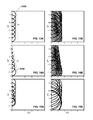
- FIGS. 13A-E are images of wavefront formation for TTD simultaneous turn-on for a plurality of timings ⁇ .
- FIGS. 14A-E are images of wavefront formation for TTD sequential turn-on for a plurality of timings ⁇ .
- FIGS. 15A-E are images of differences in wavefront formation between TTD simultaneous turn-on and TTD sequential turn-on for a plurality of timings ⁇ .
- FIG. 16 illustrates an exemplary system for modifying the intermediate frequency (IF) waveforms prior to conversion to RF signals.
- FIG. 17 is a normalized RF antenna array pattern for mono-pulse (tracking) mode.
- FIG. 18 is a normalized RF antenna array pattern for imaging mode.
- FIG. 19 is a normalized RF antenna array pattern for CPS beam steering at IF or RF.
- FIG. 20 is a normalized RF antenna array pattern for IF-based TTD RF beam steering.
- FIG. 21 illustrates a system for formation of a broadband TTD digital beam.
- FIG. 22 is a flow diagram illustrating an exemplary methodology for generating IF waveforms prior to conversion to RF signals.
- FIG. 23 is a flow diagram illustrating an exemplary methodology for modifying IF waveforms prior to conversion to RF signals.
- FIG. 24 is a continuation of the flow diagram of FIG. 9 illustrating an exemplary methodology for modifying IF waveforms prior to conversion to RF signals.
- FIG. 25 is a flow diagram illustrating an exemplary methodology for processing one or more echo pulses.
- FIG. 26 illustrates an exemplary computing device.
- the term “or” is intended to mean an inclusive “or” rather than an exclusive “or”. That is, unless specified otherwise, or clear from the context, the phrase “X employs A or B” is intended to mean any of the natural inclusive permutations. That is, the phrase “X employs A or B” is satisfied by any of the following instances: X employs A; X employs B; or X employs both A and B.
- the articles “a” and “an” as used in this application and the appended claims should generally be construed to mean “one or more” unless specified otherwise or clear from the context to be directed to a singular form.
- the term “exemplary” is intended to mean serving as an illustration or example of something, and is not intended to indicate a preference.
- the intermediate frequency will be referenced as lower than the RF, requiring up-conversion to RF.
- a higher IF can be combined with down-conversion to a lower RF to achieve beam steering, or other application that can benefit from signal conversion in the IF and RF domain.
- Performing PS and/or TTD at IF is favorable from a component selection perspective, particularly when commercial direct digital synthesis (DDS) components (e.g., integrated circuits or chips) are readily available that meet Shannon's sampling criterion, whereby such DDS components can be manufactured to include TTD and PS components, e.g., with arbitrary amplitude.
- DDS direct digital synthesis
- signal and “waveform” are used interchangeably herein, whereby a signal (or pulse) can have a particular waveform, and a waveform can identify a shape construct of a signal.
- FIG. 1 illustrates a system 100 , e.g., an array antenna, configured to enable broadband TTD electronic beam steering on transmit and receive by generating IF signals having one or more delayed components via digital signal processing.
- System 100 illustrated in FIG. 1 comprises a plurality of channels and included components to enable signaling from a signal module 101 .
- the signal module 101 can generate signals for transmission (and reception) over a plurality of channels and antenna elements.
- Channels 102 and 103 are discussed herein, however the described components and methodologies related thereto are applicable to all of the n channels which can form an array antenna (where n is a integer greater than zero).
- the signal module 101 can generate a first signal (having a first waveform) 104 on the first channel 102 , whereby the first signal 104 is generated, processed, and/or modified by various components included in the first channel 102 , and finally is transmitted as a first emitted signal 105 at the antenna element 106 . Further, the signal module 101 can generate a second signal (having a second waveform) 107 on the second channel 103 , whereby the second signal 107 is generated, processed, and/or modified by various components included in the second channel 103 , and finally is transmitted as a second emitted signal 108 at the antenna element 109 .
- the emitted signals 105 and 108 , and a plurality of signals generated by the other n channels (not shown), can combine to form a steerable beam 190 .
- the first signal 105 and the second signal 107 can be emitted with required true time delay for ultra-wide-band beam steering.
- the signal module 101 includes a digital source 110 , which can generate a digital signal 111 .
- the signal module 101 can further include a processor/controller 112 (hereinafter controller 112 ), whereby the controller 112 can control generation and/or modification of signals at the signal module 101 , and further, process signals received at the signal module 101 .
- controller 112 a processor/controller 112
- the signal module 101 can further include a waveform generator 113 (e.g., an arbitrary waveform generator (AWG)).
- the AWG 113 can be utilized to receive a digital signal 111 (e.g., for each of the channels 102 , 103 , n), and in accordance with one or more embodiments presented herein, the AWG 113 can convert each digital signal 111 into a respective analog signal, e.g., generate signals 104 and 107 both having an analog format.
- the AWG 113 can comprise of one or more digital to analog convertors (DACs).
- the AWG 113 and the controller 112 can operate in conjunction with a DDS component 115 .
- the DDS component 115 can include a time ( ⁇ ) component 116 (e.g., a TTD component), a phase ( ⁇ ) component 117 (e.g., a PS or a constant phase shift (CPS) component), and an amplitude component 118 .
- the time component 116 , the phase component 117 , and the amplitude component 118 can be physical components, e.g., the time component 116 can be a time shifter, the phase component 117 can be a phase shifter, and the amplitude component 118 can be an attenuator.
- a digital signal 111 can be processed at one or more of the time component 116 , the phase component 117 , and/or the amplitude component 118 .
- the DDS component 115 can be a virtual component, e.g., an algorithm, settings, instructions, etc., which can be utilized to control conversion of a plurality of signals (e.g., signals 104 and 107 ) from digital format (e.g., digital signal 111 ) to analog format.
- a plurality of signals e.g., signals 104 and 107
- digital format e.g., digital signal 111
- at least one of the timing, phase and/or amplitude can be configured such that the generated analog signal (e.g., signal 104 and/or signal 107 ) can be generated with a desired timing, phase and/or amplitude, as further described herein.
- system 100 can further include a conversion module 120 which can be utilized to convert signals having an intermediate frequency (IF) to a radio frequency (RF) and vice versa, as required to enable signal transmission and reception.
- the conversion module 120 can include one or more mixers, e.g., mixers 121 and 122 .
- the conversion module 120 is not necessary if the T/R modules and antennas can directly operate at IF frequencies, i.e., where the IF is the RF.
- a first portion of the circuitry of channel 102 between the signal module 101 and the conversion module 120 comprises a first IF portion 123 , which connects the channel 102 from the signal module 101 to an IF input port 124 of a first mixer 121 .
- the channel 103 includes a second IF portion 125 which is connected to an IF input port 126 of the second mixer 122 .
- a connector 195 can be utilized to enable connection of the IF portion of system 100 to an RF portion of system 100 , thereby enabling a “plug and play” approach to incorporation of the IF portion of system 100 to the RF portion of system 100 .
- a local oscillator 131 is connected to the mixers 121 and 122 , respectively by LO input port 127 and an LO input port 128 , whereby an oscillator signal 132 generated by the LO 131 can be configured to modify the respective signals 104 and 107 in their IF form to RF form.
- the oscillator signal 132 can be a carrier signal, such as a sinusoidal continuous wave signal, a square wave signal, etc.
- the LO 131 can be connected to the LO input ports 127 and 128 via a circuit 135 and power divider 136 , whereby circuit 135 can be a corporate-fed circuit. While not shown in FIG. 1 , the circuit 135 can be connected to n other mixers included in the conversion module 120 , whereby the n other mixers form part of the n channels connected to the signal module 101 .
- the channels 102 and 103 further include respective RF portions 140 and 141 , which are coupled to the respective mixers 121 and 122 .
- the RF portion 140 can be connected to an RF output port 129 of the mixer 121
- the RF portion 141 can be connected to an RF output port 130 of the mixer 122 .
- the IF portions 123 and 125 , and the RF portions 140 and 141 can be transmission lines having respective lengths l 1 , l 2 , l 3 and l 4 .
- the mixers 121 and 122 enable respective signals 104 and 107 having an intermediate frequency at the IF input ports 124 and 126 to be converted to RF frequencies for transmission as emitted signals 105 and 108 , whereby conversion from an IF to a RF can be in accordance (e.g., mixed) with the oscillator signal 132 .
- Transmission of the first signal 104 in RF form on channel 102 is via the antenna 106
- transmission of the second signal 107 in RF form on channel 103 is via the antenna 109 .
- respective transmit and receive (T/R) modules 170 and 171 can be located between respective mixer and antenna pairings, e.g., between mixer 121 and antenna 106 , and between mixer 122 and antenna 109 .
- operation of the DDS component 115 can be controlled in accordance with a controller 112 .
- the controller 112 can include a beam steering algorithm 196 . Accordingly, when the DDS component 115 is a virtual component, the controller 112 can utilize the DDS component 115 to configure respective values for at least one of a time delay (e.g., the time component 116 ), a phase (e.g., the phase component 117 ), and/or an amplitude (e.g., the amplitude component 118 ) for a waveform generated on each of the channels 102 , 103 , n, etc.
- a time delay e.g., the time component 116
- a phase e.g., the phase component 117
- an amplitude e.g., the amplitude component 118
- the DDS component 115 can be virtually applied at the AWG 113 , such that each waveform has the desired time delay, phase shift, amplitude, etc., to achieve one or more signaling parameters defined in the beam steering algorithm 196 .
- System 100 can further include a data store 197 .
- the controller 112 can access the data store 197 to enable storage and retrieval of one or more parameters and/or values (e.g., beam steering parameters, characteristics of various components and circuitry forming system 100 , etc.) to enable beam steering (e.g., in accordance with the beam steering algorithm 196 ).
- parameters and/or values e.g., beam steering parameters, characteristics of various components and circuitry forming system 100 , etc.
- the signal module 101 can further include an analog to digital convertor (ADC) 114 to convert received analog signals to a digital format.
- a signal e.g., an echo signal or pulse 198 and/or 199
- the antennas e.g., antenna 106 and/or 109
- the respective mixer e.g., mixer 121 or 122
- conversion from analog to digital format e.g., at the ADC 114
- the received pulse 198 and/or 199 can undergo processing at the controller 112 , whereby the controller 112 can operate in conjunction with the DDS component 115 and/or the beam steering algorithm 196 .
- the received signal 198 and/or 199 can be processed in accordance with any conditions applied to the one or more signals 104 and 107 during generation of the signals 104 and 107 .
- the AWG 113 can perform DDS using high-speed multi-channel DACs. Accordingly, during signal transmission, as shown by the dashed box, the DDS 115 can perform amplitude change, phase shifting and/or time delay. While on signal receive, the controller 112 after the ADC 114 can perform the same amplitude change, phase shifting and/or time delay processing utilizing the DDS 115 .
- the DDS component 115 can be either a standalone component (or a plurality of components 116 , 117 , and 118 ), or the DDS component 115 can be incorporated into another component.
- the DDS component 115 can be incorporated into a digital signal processor (DSP) (not shown).
- DSP digital signal processor
- Such a DSP can be a digital to analog (D/A) convertor (not shown), which can perform any required signal conversion.
- the DDS component 115 can be operated at a sub-array level rather than at the antenna level of system 100 .
- signal module 101 can generate the signals 104 and 107 with baseband frequency bandwidth of about 3 GHz.
- the signals 104 and 107 can have an IF of about 0.4 GHz to about 3.4 GHz.
- the signals 104 and 107 can be up-converted to RF at X-band, K, Ku, Ka, etc., by varying the frequency of 132 .
- the various embodiments presented herein can also be utilized with the visible portion of the electromagnetic spectrum, e.g., frequencies from about 0 Hz up to about 790 THz.
- RF beam shaping e.g., amplitude tapered aperture
- IF signal e.g., signals 104 and/or 107
- Amplitude control of the IF channels also makes possible multi-channel amplitude equalization, wherein amplitude equalization can be a calibration step in addition to phase and delay calibration.
- the main difference between TTD and CPS is the manner at which k n in ⁇ n is generated.
- f 0 is typically selected to be at the band center.
- ⁇ 0 - ⁇ ⁇ ⁇ f f 0 ⁇ tan ⁇ ⁇ ⁇ 0 Eqn . ⁇ 3
- ⁇ n 2 ⁇ ⁇ ⁇ ⁇ f 0 c 0 ⁇ r ⁇ n ⁇ r ⁇ 0 > m n ⁇ 2 ⁇ ⁇ (whereby m n is an integer) then a new direction of maximum ⁇ circumflex over (r) ⁇ ′ 0 exists such that
- Digital waveforms are capable of synthesizing delay with a time-domain resolution less than the inverse of its sampling rate, i.e.
- ⁇ sin ⁇ ⁇ ⁇ 2 ⁇ ⁇ f ; where, ⁇ is the steering angle from a boresight (e.g., as indicated in FIG. 1 ) and
- Effective delay may be made to be smaller than available from a quantized clock if the amplitude of a digital signal is taken into consideration.
- An exemplary N-bit digital-to-analog convertor (DAC) can have a magnitude resolution of
- g 1 and g 2 be the quantized versions g 1 and g 2 , respectively.
- the fidelity with which g 2 represents g 2 can possibly be found by comparing the phase differences (which contain information about ⁇ ) between their Fourier transforms G 2 and G 2 .
- FIGS. 2-11 a plurality of schematic representations are presented to illustrate utilization of CPS and TTD at an IF signal portion of a radar generation system to delay a subsequently produced RF signal portion of the radar generation system.
- Each of the schematics in FIGS. 2-11 illustrate a single channel and various effects (e.g., comparability or non-comparability of configurations) which can be engendered based upon respective phase modification(s) and timing modification(s) on particular circuit configurations 200 - 1100 .
- FIGS. 2-11 are schematics, various components illustrated in FIGS. 2-11 are comparable to components presented in system 100 . Further, to enhance readability, the common components in configurations 200 - 1100 are numbered in FIG. 2 .
- the common components and numbering are carried across all of the configurations 200 - 1100 .
- the common components are a waveform 204 (e.g., comparable to waveforms 104 and 107 ), transmitted in an IF form 210 (e.g., comparable to IF portions 123 or 125 ) to an IF input port 221 of a mixer 220 (e.g., comparable to mixers 121 , 122 ), whereby the IF input port 221 is comparable to IF input ports 124 , 126 .
- a LO input port 222 of the mixer 220 is connected to a LO 230 (e.g., comparable to LO 131 ), whereby the LO input port 222 is comparable to LO input ports 127 , 128 .
- the waveform 204 can undergo conversion based upon an oscillator signal 231 (e.g., comparable to oscillator signal 132 ) from the LO 230 , whereby the up-converted waveform generated at the mixer 220 can be transmitted from the mixer 220 at a RF output port 223 to the RF portion 240 (e.g., comparable to RF channel portions 140 , 141 ).
- the RF output port 223 is comparable to the RF output ports 129 , 130 .
- the waveform 204 in RF form can be transmitted from antenna 206 (e.g., comparable to antenna elements 106 , 109 ) as a signal 205 (e.g., comparable to signals 105 , 108 ) which can be combined with other signals to form a steerable beam (not shown, but comparable to beam 190 ).
- antenna 206 e.g., comparable to antenna elements 106 , 109
- signal 205 e.g., comparable to signals 105 , 108
- steerable beam not shown, but comparable to beam 190 .
- FIGS. 2-4 indicate that applying CPS 250 at the RF output port 223 of the mixer 220 ( FIG. 2 ) is the same as applying CPS 350 at the IF input port 221 of the mixer 220 ( FIG. 3 ), which is also the same as applying CPS 450 to the LO input port 222 of the mixer 220 ( FIG. 4 ). Further CPS can be applied in partial combination, whereby a first CPS portion 550 at the IF input port 221 and a second CPS portion 555 at the LO input port 222 ( FIG. 5 ) of the mixer 220 can be utilized, and the configuration 500 has the same result as the respective application of CPS in configurations 200 , 300 , and 400 .
- FIGS. 6-9 present a plurality of schematic representations, whereby the CPS components (e.g., CPS components 250 , 350 , 450 , 550 and 555 ) of FIGS. 2-5 are replaced with ideal TTD components.
- CPS components e.g., CPS components 250 , 350 , 450 , 550 and 555
- FIG. 6 illustrates a TTD component 650 located on the RF portion 240 (e.g., at the RF output port 223 ), while FIG. 7 illustrates a TTD component 750 on the IF portion 210 (e.g., at the IF input port 221 ).
- FIG. 8 illustrates a TTD component 850 located on the LO signaling portion 231 (e.g., at the LO input port 222 ).
- FIG. 9 illustrates a first TTD component 950 on the IF portion 210 (e.g., at the IF input port 221 ), and a second TTD component 955 on the LO signaling portion 231 (e.g., at the LO input port 222 ).
- TTD of a oscillator signal 231 requires a high-frequency RF component(s), e.g., configuration 900 can be costly and inefficient.
- equivalence can require the delay imposed by the TTD component 955 to be indistinguishable from that imposed by the TTD component 950 .
- the oscillator signal 231 (and oscillator signal 132 ) for numerous radar systems is a single-tone carrier signal at f 0 .
- CPS may be moved from any port (e.g., any of ports 221 , 222 , 223 ) of the mixer 220 to any other port as illustrated in the configurations presented in FIGS. 2-5 .
- any port e.g., any of ports 221 , 222 , 223
- the CPS 1050 of the oscillator signal 231 can be moved to the IF input port 221 of the mixer 220 (e.g., configuration 1100 ), as indicated by the broken line between FIGS. 10 and 11 .
- a DDS component 160 can be applied at an IF input port of a mixer (e.g., any of mixers 121 , 122 , 220 ), whereby the DDS component 160 can comprise a time component (e.g., any of time components 116 , 1170 ) and a phase component (e.g., any of phase components 117 , 1050 ), whereby a time component can perform TTD and a phase component can perform CPS.
- TTD on an RF portion e.g., any of RF portions 140 , 141 , or 240 from any of RF output ports 129 , 130 , or 223
- the IF portion e.g., at any of IF input ports 124 , 126 , or 221
- FIG. 12 presents a schematic 1200 of four signals having waveforms 1201 - 1204 being generated at four antenna elements 1211 - 1214 , whereby the antennas 1211 - 1214 are included in an array antenna (not shown). It is to be appreciated that while only four antenna elements 1211 - 1214 are illustrated, the various embodiments are applicable to an array antenna comprising M ⁇ N antenna elements, whereby M and N are positive integers greater than zero.
- the four waveforms 1201 - 1204 represent the respective waveform at t ⁇ 0, further four waveforms 1205 - 1208 represent the respective waveform for t ⁇ 0.
- the rising edges of the lines 1221 - 1224 presented in FIG. 12 indicates pulses being generated at each antenna element 1211 - 1214 can be sequentially delayed for beam steering to occur.
- the dashed line 1230 and points 1231 - 1234 indicate a corresponding wave initiation in time for phase synchronization.
- a pulse generator capable of picosecond delay at each element 1221 - 1224 to accomplish such a feat is neither practical nor necessary.
- all of the antenna elements 1211 - 1214 of an antenna array can be pulsed simultaneously after DDS IF-modulation (e.g., by DDS component 115 ), e.g., the various embodiments presented herein enable a wave generator (e.g., AWG 113 ) having a plurality of channels (e.g., channel 102 , channel 103 . . . channel n) to output waveforms 1201 - 1204 at the same time (e.g., concurrently), however, each of the waveforms 1201 - 1204 can have a different initial phase.
- a wave generator e.g., AWG 113
- channels e.g., channel 102 , channel 103 . . . channel n
- the waveforms 1201 - 1204 are shown as having waveforms of a constant periodicity, the waveforms 1201 - 1204 can also be chirps such that the respective chirp initiation (e.g., low chirp) and chirp termination (e.g., high chirp) for each waveform can be configured such that the beam (e.g., the beam 190 ) formed from the respective chirps is steered as required, e.g., in accordance with a beam steering algorithm (e.g., beam steering algorithm 196 ).
- a beam steering algorithm e.g., beam steering algorithm 196
- multiple pulse-modulated IF waveform generation e.g., waveforms 104 , 107 , 204
- LO feed signaling e.g., oscillator signals 132 , 231
- may be synced across all of the antenna elements 1211 - 1214 by equal or unequal path length transmission lines e.g., by any of the respective lengths l 1 , l 2 , l 3 and l 4 , per FIG. 1 ).
- residual delays and amplitude errors resulting from unequal path length transmission lines can be compensated for during a calibration operation by changing the effective TTD and CPS generated by the respective DDS components (e.g., by DDS component 115 ) and their amplitudes at the IF input port (e.g., IF input ports 124 and/or 126 ).
- time delay ( ⁇ ) and phase ( ⁇ ) compensation are performed in the digital domain (e.g., respectively by time component 116 and phase component 117 )
- the radar architecture e.g., as presented in FIGS. 1 and 11
- the beam steering algorithm 196 can be utilized to generate respective signals 105 and 108 to compensate for channel-to-channel imbalance as a function of temperature, operating environment, etc.
- Simultaneous pulsing of TTD waveforms affects the spatial transient wave front formation process of the radiated beam, e.g., beam 190 .
- the shape of the rising edge of the detected pulse e.g., any of pulse waveforms 1201 - 1204
- TTD sequential pulsing The following is an examination of waveforms generated by both TTD simultaneous pulsing (per the embodiments presented herein) and also TTD sequential pulsing.
- a time delay between the n th element location ⁇ right arrow over (r) ⁇ n and the observer's position ⁇ right arrow over (r) ⁇ can be considered to be
- ⁇ n r ⁇ - r ⁇ n c 0 , where c 0 is the speed of light in vacuum.
- n r ⁇ n ⁇ r ⁇ n c 0 is the time delay required for steering to the direction ⁇ circumflex over (r) ⁇ 0 .
- FIGS. 13A-E relate to wave front formation based upon F( ⁇ right arrow over (r) ⁇ ,t), e.g., simultaneous turn-on (per the embodiments presented herein), whereby the wave front is comparable to a wavefront of beam 190 , per FIG. 1 .
- FIGS. 13A-E relate to wave front formation based upon F( ⁇ right arrow over (r) ⁇ ,t), e.g., simultaneous turn-on (per the embodiments presented herein), whereby the wave front is comparable to a wavefront of beam 190 , per FIG. 1 .
- FIGS. 14A-E relate to wave front formation based upon G( ⁇ right arrow over (r) ⁇ ,t), e.g., sequential turn-on
- FIGS. 15A-E present the differences (e.g., F-G) between the simultaneous turn-on of FIGS. 13A-13E and the sequential turn-on of FIGS. 14A-14E .
- a ⁇ /2 inter-element spacing and TTD for 10° steering were applied.
- FIGS. 13A, 14A , and 15 A are for ⁇ N
- FIGS. 13B, 14B, and 15B are for 3 ⁇ N
- FIGS. 13C, 14C, and 15C are for 5 ⁇ N
- FIGS. 13D, 14D, and 15D are for 7 ⁇ N
- FIGS. 13E, 14E, and 15E are for 9 ⁇ N .
- each of the antenna elements in FIG. 13A are configured for simultaneous turn-on for transmission (e.g., simultaneous turn-on of respective signals 1350 ), as evidenced by the flat wavefront w 1 , compared with the sequential turn-on (e.g., sequential turn-on of respective signals 1450 ) of the antenna elements in FIG. 14 engendering an angled wavefront w 2 .
- FIGS. 13-15 it is evident from FIGS. 13-15 , that while the wave front transients for both F( ⁇ right arrow over (r) ⁇ ,t) (e.g., FIGS. 13A-13E ) and G( ⁇ right arrow over (r) ⁇ ,t) (e.g., FIGS.
- FIG. 16 is a schematic of a radar system 1600 utilized during the experiment.
- the radar system 1600 comprises a transmit array antenna comprising two short differentially-fed Ku-band horns 1601 and 1602 spaced at 48.4 mm or ⁇ 3 ⁇ at 18.2 GHz.
- Such a large spacing was selected to illustrate the steering inability of digital-emulated PS at IF beyond modulo-2 ⁇ ; whereas digital-emulated TTD has no such limitations.
- Differential feeding was utilized to benefit from the improved detection sensitivity of null steering.
- Input match and isolation of the horns' 1601 and 1602 were improved by attachment of respective RF isolators 1603 and 1604 .
- the isolators 1603 and 1604 in turn connect to the RF output ports 1623 and 1624 of two Ku-band mixers 1605 and 1606 .
- the LO input ports 1621 and 1622 of the mixers 1605 and 1606 are tied together via a 3-dB power splitter 1607 and fed by a 10-dBm 15.1-GHz RF source signal 1631 from a LO 1608 .
- the IF input ports 1622 and 1625 of the mixers 1605 and 1606 respectively connect to separate channels 1609 and 1610 of a 12 Gs/s signal module 1690 .
- the signal module 1690 can include an AWG 113 which is programmed to output modified linear chirps 1611 , 1612 from about 0.1 to about 3.1 GHz every 20 ms over the two synchronized channels 1609 and 1610 .
- the AWG 113 can be operating in conjunction with a virtual DDS component 1660 , for example, the controller 112 can utilize the beam steering algorithm 196 (in conjunction with parameters, etc., stored on memory device 197 ) to define respective values and/or conditions for each of the time ( ⁇ ) component 116 , the phase ( ⁇ ) component 117 , and the amplitude component 118 for the waveforms 1611 and 1612 .
- FIGS. 17 and 18 present normalized antenna array patterns (e.g., ultra-wide band UWB) illustrating mode switching between a mono-pulse mode (e.g., tracking) per FIG. 17 , and an imaging mode, per FIG. 18 .
- a peak 1810 over the entire frequency range of the chirp is shown in FIG. 18 .
- a CPS centered at 16.7 GHz
- FIG. 21 illustrates a system 2100 for formation of a broadband TTD digital beam, wherein system 2100 can be an array antenna such as a multi-phase-center radar configured to perform TTD delay at each antenna element.
- System 2100 can comprise n channels transmitting and receiving signals via n antenna elements, whereby the system 2100 can operate in accordance with one or more embodiments as presented herein, e.g., system 2100 further illustrates a DDS component(s) being incorporated into a system that can both transmit one or more radar signals (or pulses) and further receive and process one or more radar echoes.
- a digital transceiver 2101 can be utilized to generate and receive respective signals across system 2100 , whereby transceiver 2101 can generate signals in a manner similar to AWG 113 .
- the respective channels can be considered as three separate portions, an IF digital portion 2102 , an IF analog portion 2103 , and a RF front end portion 2104 .
- a first transmission circuit 2105 of the first channel CH 1 includes a DDS 2106 and a low pass filter 2107 .
- the DDS 2106 can include one or more components as previously described, such as a time component (e.g., 116 ), a phase component (e.g., 117 ), and/or an amplifier (e.g., 118 ).
- an multiplier 2108 and a band pass filter 2109 can be utilized to intermediately convert an IF signal prior to up-conversion to an RF signal at the mixer 2110 .
- Mixer 2110 can be mixed with a oscillator signal 2111 generated by an oscillator 2112 , whereby the oscillator signal 2111 can be transmitted to the mixer 2110 via a corporate fed network 2113 which includes one or more splitters 2114 .
- the signal can pass through a band pass filter 2115 and further transmitted along a first RF transmission circuit 2116 for transmission via a first antenna element 2117 (ANT 1 ).
- the first RF transmission circuit 2116 can include an amplifier 2118 .
- An echo signal can be received at the first antenna element 2117 , which can be passed along the RF receiver circuit 2119 .
- the receiver circuit 2119 can include an amplifier 2120 , whereby the echo signal can further pass through the band pass filter 2115 , before being down-converted at the mixer 2110 from an RF signal to an IF signal.
- the IF echo signal can be received on the IF receiver circuit 2121 and accordingly processed at a sweep and hold (S&H) device 2122 and an analog to digital convertor (ADC) 2123 , to be subsequently processed at CH 1 of the digital transceiver 2101 .
- S&H sweep and hold
- ADC analog to digital convertor
- a plurality of channels can be serviced by the digital transceiver 2101 .
- Components and circuitry comprising CH n can be the same as that utilized in CH 1 , with comparable components being indicated by common circuitry symbols.
- a second IF transmission channel 2124 can include a DDS component 2125 , a low pass filter 2126 , a multiplier 2127 , and a band pass filter 2128 .
- Up-conversion from IF to RF can be performed at a mixer 2129 connected to the LO 2112 .
- the RF signal can pass through a band pass filter 2131 , and be transmitted by antenna element 2133 (ANT n ), via a RF transmission circuit 2130 which can include an amplifier 2132 .
- Echo reception on the CH n can be via a second RF receiver circuit 2134 , which can include an amplifier 2135 .
- Down-conversion of the RF echo to IF can be via mixer 2129 .
- Reception of the IF echo at the digital transceiver 2101 can be via an IF receiver circuit 2140 , which can include a S&H device 2137 and an ADC 2138 .
- Low-side-levels can be achieved by applying amplitude tapering digitally at the IF region 2102 .
- various hardware implementation workarounds can be utilized to achieve desired time and amplitude quantization on delayed signal representation, and any effects associated therewith. For example, rather than digitally generating the entire 3 GHz of IF bandwidth (e.g., per FIGS. 17-20 ), analog frequency multipliers and filtering can be utilized to increase the bandwidth of digitally synthesized IF signal prior to up conversion.
- FIGS. 22-25 illustrate exemplary methodologies relating to beam steering an array antenna by modifying lower and/or IF waveforms prior to conversion to RF signaling. While the methodologies are shown and described as being a series of acts that are performed in a sequence, it is to be understood and appreciated that the methodologies are not limited by the order of the sequence. For example, some acts can occur in a different order than what is described herein. In addition, an act can occur concurrently with another act. Further, in some instances, not all acts may be required to implement the methodologies described herein.
- FIG. 22 illustrates a methodology 2200 relating to modifying lower frequency and/or IF waveforms prior to conversion to RF signaling to enable beam steering of an array antenna.
- one or more required steering conditions for an array antenna can be determined.
- the steering conditions can be a function of a location of the array antenna and a direction to a target of interest, a function of circuitry forming the antenna array (e.g., length of respective transmission lines), etc.
- the required steering conditions can be determined by a controller component, whereby the controller component can utilize a beam steering algorithm to enable a plurality of signals to be transmitted such that the signals interact (e.g., constructively and/or destructively interfere) to form the steered beam, whereby individual output conditions for each antenna element can relate to a reference beam (e.g., signal conditions of a second transmission signal relative to a first transmission signal), as well as compensating for such effects as individual transmission line length, etc.
- a reference beam e.g., signal conditions of a second transmission signal relative to a first transmission signal
- the respective required steering conditions can be stored in a memory device for subsequent retrieval by the controller component.
- a first waveform can be generated on a first channel of a waveform generator, and also a second waveform can be generated on a second channel of the waveform generator.
- the waveform generator can be operating in conjunction with the controller component, wherein the controller component utilizes a DDS component to enable generation of the first waveform and the second waveform.
- the DDS component can be an algorithm, instructions, etc., which can operate on the waveform generator such that the first waveform can be generated with a required first timing, first phase, and/or first amplitude and the second waveform can be generated with a required second timing, second phase, and/or second amplitude.
- the DDS component can operate in accordance with one or more values generated by the beam steering algorithm.
- the first waveform can be configured as a reference waveform (or a base waveform) and the second waveform can be configured such that a beam formed with the first waveform and the second waveform is accordingly steered.
- At least one of the first IF waveform or the second IF waveform can be modified in accordance with one or more outputs generated by the beam steering algorithm.
- the first IF waveform can have different signal form and timing compared to the second IF waveform.
- the first IF waveform can act as a reference waveform, against which the second IF waveform is modified.
- the second IF waveform can have its phase modulated such that a peak amplitude of the second IF waveform is reached 1 picosecond later than the first IF waveform reaches its peak amplitude.
- the first IF waveform and the second IF waveform can be generated in accordance with a required beam steering, e.g., respectively having desired amplitude(s), phase(s), and/or time delay(s).
- the first IF waveform can be converted to form a first RF signal
- the second IF waveform can be converted to form a second RF signal.
- the conversion of the first IF waveform can be performed at the first mixer, whereby the conversion is performed in conjunction with an oscillator signal received at a first LO input port of the first mixer.
- the converted first RF signal can be output from the mixer on a first RF output port.
- the conversion of the second IF waveform can be performed at the second mixer, whereby the conversion is performed in conjunction with the oscillator signal received at a second LO input port of the second mixer.
- the up-converted second RF signal can be output from the mixer on a second RF output port.
- the oscillator signal received at the first LO input port of the first mixer can be a common signal to the oscillator signal received at the second LO input port of the second mixer.
- the first RF signal can be transmitted from a first antenna element located on the first channel as a first transmitted signal
- the second RF signal can be transmitted as a second transmitted signal from a second antenna element located on the second channel.
- the first RF signal and the second RF signal combine to form a steerable beam (in conjunction with n RF signals being generated from n other antenna elements included in the array antenna), whereby, through constructive and destructive interference, an amplitude in the steerable beam is directed towards the direction of the target of interest.
- FIGS. 23 and 24 illustrate a methodology 2300 relating to modifying lower and/or IF waveforms prior to conversion to RF signaling to enable beam steering of an array antenna.
- one or more required steering conditions for an array antenna can be determined.
- the steering conditions can be a function of a location of the array antenna and a direction to a target of interest, a function of circuitry forming the antenna array (e.g., length of respective transmission lines).
- the required steering conditions can be identified by a controller component, whereby the controller component can utilize a beam steering algorithm to enable a plurality of signals to be transmitted such that the signals interact (e.g., constructively and/or destructively interfere) to form the steered beam, whereby individual output conditions for each antenna element can relate to a reference beam (e.g., signal conditions of a second transmission signal relative to a first transmission signal), as well as compensating for such effects as individual transmission line length, etc.
- a reference beam e.g., signal conditions of a second transmission signal relative to a first transmission signal
- the respective required steering conditions can be stored in a memory device for subsequent retrieval by the controller component.
- a first waveform can be generated on a first channel of a waveform generator, and also a second waveform can be generated on a second channel of the waveform generator.
- the first waveform and the second waveform can initially be generated by the wave generator with a baseband spectral magnitude, whereby the first waveform and the second waveform can subsequently be modulated to respectively form a first IF waveform and a second IF waveform.
- the first waveform and the second waveform can be generated by the wave generator as a first IF waveform and a second IF waveform.
- the first IF waveform can be received at a first DDS component, whereby the DDS component comprises a first TTD component and a first CPS component.
- the first DDS component can be located on the first channel, e.g., at an IF input port of a first mixer.
- the second IF waveform can be received at a second DDS component, whereby the DDS component comprises a second TTD component and a second CPS component.
- the second DDS component can be located on the second channel, e.g., at an IF input port of a second mixer.
- At 2360 at least one of the first IF waveform or the second IF waveform can be modified in accordance with one or more outputs generated by the beam steering algorithm.
- the first IF waveform can have different signal form and timing compared to the second IF waveform.
- the first IF waveform can act as a reference waveform, against which the second IF waveform is modified.
- the second IF waveform can have its phase modulated such that a peak amplitude of the second IF waveform is reached 1 picosecond later than the first IF waveform reaches its peak amplitude.
- the modified first IF waveform can be up-converted to form a first RF signal
- the modified second IF waveform can be up-converted to form a second RF signal.
- the conversion of the first IF waveform can be performed at the first mixer, whereby the conversion is performed in conjunction with an oscillator signal received at a first LO input port of the first mixer.
- the converted first RF signal can be output from the mixer on a first RF output port.
- the conversion of the second IF waveform can be performed at the second mixer, whereby the conversion is performed in conjunction with the oscillator signal received at a second LO input port of the second mixer.
- the up-converted second RF signal can be output from the mixer on a second RF output port.
- the oscillator signal received at the first LO input port of the first mixer can be a common signal to the oscillator signal received at the second LO input port of the second mixer.
- the first RF signal can be transmitted from a first antenna element located on the first channel as a first transmitted signal
- the second RF signal can be transmitted as a second transmitted signal from a second antenna element located on the second channel.
- the first RF signal and the second RF signal combine to form a steerable beam (in conjunction with n RF signals being generated from n other antenna elements included in the array antenna), whereby, through constructive and destructive interference, an amplitude in the steerable beam is directed towards the direction of the target of interest.
- FIG. 25 illustrates a methodology 2500 relating to processing of one or more received echo pulses (received signals, returned signals) to facilitate identification of information conveyed by the echo pulses (e.g., target information, terrain information, etc.).
- one or more echo pulses are received at an antenna array, whereby the echo pulses are received as a function of transmitted signals being reflected off such objects/features as moving targets, stationary targets, terrain, natural features, manmade features, etc.
- the transmitted signals form part of a steered beam, which as previously described, the transmitted signals can be generated and/or modified in conjunction with a DDS component (e.g., either a physical component(s) or a virtual component(s)) to enable the transmitted signals to be respectively time delayed, phase shifted, and/or amplitude adjusted as required to form a steered beam.
- DDS can be applied to a transmittable signal prior to conversion from IF to RF.
- the one or more echo pulses can be frequency converted from RF to IF, whereby the frequency conversion can be performed by one or more mixers.
- the one or more echo pulses can be received in analog format. Accordingly, to enable processing of the one or more echo pulses, the one or more echo pulses can be converted from analog format to digital format, e.g., by an ADC.
- the one or more echo pulses can be processed to enable target determination, etc.
- the one or more echo pulses can be processed in accordance with information, parameters, etc., utilized during the formation of the one or more echo pulses for transmission.
- the processing can be in accordance with knowledge of how the one or more echo pulses were generated and/or modified during a DDS operation(s) utilized during formation of the one or more echo pulses.
- the processing can also be performed in conjunction with knowledge of how the transmitted signals were formed in accordance with a beam steering algorithm.
- processing of the one or more echo pulses can be performed by a processor utilizing DDS and the beam steering algorithm.
- initiation of transmission of the first RF signal and the second RF signal can be at the same turn-on time.
- the difference in phase can be considered equivalent to a timing delay required to enable the constructive and destructive interference such that the beam is steered towards the direction of interest.
- IF signals being typically lower in frequency than RF signals
- generation, transmission, reception, and processing of IF signals may be implemented by mixed-signal means via DACs and/or DDS, ordinary transmission lines, ADCs, and digital signal processors (DSPs), respectively.
- DSPs digital signal processors
- An IF subsystem can be integrated with compatible RF antenna-array frontends to accommodate any radar or communications band, with essentially no change to the underlying hardware, enabling achievement of component commonality among disparate systems.
- IF subsystems e.g., the IF portion of system 100
- the relocation of beam steering responsibilities from RF to IF eliminates a requirement to utilize broadband analog phase shifters (APS) and/or true-time-delay (TTD) devices at RF for each antenna element or sub-array of antenna elements.
- APS phase shifters
- TTD true-time-delay
- This enables RF electronics associated with a single antenna element to better fit inside the space of ( ⁇ 0 /2) 2 to avoid the onset of grating lobes during scan, where ⁇ 0 is the shortest free-space wavelength of radiation.
- Be configuring beam steering at IF functionality of an antenna array can be reduced to distributed amplification, polarization selection, element-wise frequency up/down conversion and IF/LO feed distribution necessary for radiation and reception at RF.
- IF frequency conversion
- SSB single-side-band
- IQ in-phase and quadrature
- systems 100 , 1600 and 2100 present various configurations, one or more components or devices included in a particular configuration can be included in any of the configurations, and is not just limited to a configuration in which it is illustrated herein.
- computing device 2600 may be utilized to control measurement and determination of mutual coupling that exists between a plurality of antenna pairings in a phased array antenna.
- computing device 2600 can operate as a controller 112 operating in conjunction with a beam steering algorithm 196 .
- the computing device 2600 includes at least one processor 2602 that executes instructions that are stored in a memory 2604 .
- the instructions may be, for instance, instructions for implementing functionality described as being carried out by one or more components discussed above or instructions for implementing one or more of the methods described above.
- the processor 2602 may access the memory 2604 by way of a system bus 2606 .
- the memory 2604 may also store operating parameters, required operating parameters, and on forth.
- the computing device 2600 additionally includes a data store 2608 that is accessible by the processor 2602 by way of the system bus 2606 .
- the data store 2608 may include executable instructions, operating parameters, required operating parameters, etc.
- the computing device 2600 also includes an input interface 2610 that allows external devices to communicate with the computing device 2600 .
- the input interface 2610 may be used to receive instructions from an external computer device, from a user, etc.
- the computing device 2600 also includes an output interface 2612 that interfaces the computing device 2600 with one or more external devices.
- the computing device 2600 may display text, images, etc., by way of the output interface 2612 .
- the computing device 2600 may be a distributed system. Thus, for instance, several devices may be in communication by way of a network connection and may collectively perform tasks described as being performed by the computing device 2600 .
- the terms “component” and “system” are intended to encompass computer-readable data storage that is configured with computer-executable instructions that cause certain functionality to be performed when executed by a processor.
- the computer-executable instructions may include a routine, a function, or the like. It is also to be understood that a component or system may be localized on a single device or distributed across several devices.
- FPGAs Field-programmable Gate Arrays
- ASICs Application-specific Integrated Circuits
- ASSPs Application-specific Standard Products
- SOCs System-on-a-chip systems
- CPLDs Complex Programmable Logic Devices
- Computer-readable media includes computer-readable storage media.
- a computer-readable storage media can be any available storage media that can be accessed by a computer.
- such computer-readable storage media can comprise RAM, ROM, EEPROM, CD-ROM or other optical disk storage, magnetic disk storage or other magnetic storage devices, or any other medium that can be used to carry or store desired program code in the form of instructions or data structures and that can be accessed by a computer.
- Disk and disc include compact disc (CD), laser disc, optical disc, digital versatile disc (DVD), floppy disk, and blu-ray disc (BD), where disks usually reproduce data magnetically and discs usually reproduce data optically with lasers. Further, a propagated signal is not included within the scope of computer-readable storage media.
- Computer-readable media also includes communication media including any medium that facilitates transfer of a computer program from one place to another. A connection, for instance, can be a communication medium.
- the software is transmitted from a website, server, or other remote source using a coaxial cable, fiber optic cable, twisted pair, digital subscriber line (DSL), or wireless technologies such as infrared, radio, and microwave
- coaxial cable, fiber optic cable, twisted pair, DSL, or wireless technologies such as infrared, radio and microwave
- the coaxial cable, fiber optic cable, twisted pair, DSL, or wireless technologies such as infrared, radio and microwave
Abstract
Description
AF=Σ n=1 Nαn e jΦ
where k=2πf/c0, and {circumflex over (r)}=sin θ cos Φ{circumflex over (x)}+sin θ sin Φŷ+cos θ{circumflex over (z)} in rectangular coordinates; c0 is the speed of light in vacuum. With Φn=+kn{right arrow over (r)}n*{circumflex over (r)}0=k{right arrow over (r)}n·{circumflex over (r)}0, where {circumflex over (r)}0=sin θ0 cos Φ0{circumflex over (x)}+sin θ0 sin Φ0ŷ+cos θ0{circumflex over (z)}, the above sum would produce a maximum in the direction θ0 and Φ0. Hence, by changing Φn=−kn{right arrow over (r)}n·{circumflex over (r)}0, it is possible to steer a beam to θ0 and Φ0. The main difference between TTD and CPS is the manner at which kn in Φn is generated. In the case of TTD, kn=k=2πf/c0 whereas in CPS kn=2πf0/c0. Here, f0 is typically selected to be at the band center. Thus, from the foregoing:
Σn=1 Nαn e j2πf/c
except for when f=f0. It is possible to force the issue and make the two maximums equal to each other by changing {circumflex over (r)}0→{circumflex over (r)}′0 in the CPS expression at f≠f0. The resulting difference between {circumflex over (r)}0 and {circumflex over (r)}′0 is known as beam-pointing error. An estimate of this beam pointing error as a function of frequency change for an equal path feed array is given by:
(whereby mn is an integer) then a new direction of maximum {circumflex over (r)}′0 exists such that
This occurs for
where
is the free-space wavelength. By purposely setting the spacing between elements to
the inability of CPS to steer to directions where the phase required is greater than 2π can be ascertained (e.g., experimentally). TTD does not suffer from such issues, because any phase wrapping in Φn is precisely canceled out by the same phase wrapping in the free-space phase propagator ejk{right arrow over (r)}
This relationship enables beam steering to be realized because a time delay required for a typical array with λ/2-spaced adjacent radiators is on the order of
where, θ is the steering angle from a boresight (e.g., as indicated in
the operating frequency. For small steering angles, τ<<Δt even if fs=2f. Hence, beam angle resolution requires time delays that are accurate to a sub-clock cycle. Although this problem may be solved by increasing fs>>f, it is neither feasible nor physically practical at frequencies beyond X-band.
where A is its maximum range. Accordingly, two non-quantized, but sampled, digital signals can be considered:
where, ω=2πf. These two functions are indistinguishable from each other if the magnitude of their difference is less than half of the magnitude resolution of the DAC for all n samples. Conversely, the two signals are distinguishable if the magnitude of their difference (Δg=|g1−g2|)>0.5ΔR. It is readily apparent that the smallest τ for which this is true is given by:
(M★G)P=(∫−∞ ∞ M(v)G(v−f)dv)P Eqn. 7
(M★P)P=(MP)★G=M★(GP), Eqn. 8
as respectively identified in
(M★G)P≠(MP)★G≠M★(GP), Eqn. 9
and accordingly, the
where c0 is the speed of light in vacuum. Further,
is the time delay required for steering to the direction {circumflex over (r)}0. Ignoring propagation losses, the wave amplitude as a function of position {right arrow over (r)} and time t for the case of simultaneously-turned-on but TTD sinusoidal excitation with angular frequency may be expressed as:
F({right arrow over (r)},t)=Σn=1 N U(τn −t)cos(ω(t−τ 0,n−τn)), Eqn. 10
where U(t)=1, t≧0, U(t)=0, t<0 is the standard unit-step function. Similarly, for the case of sequential-turned-on but TTD sinusoidal excitation, the following expression can be derived:
G({right arrow over (r)},t)=Σn=1 N U(τn−(t−τ 0,n))U(t−τ 0,n)cos(ω(t−τ 0,n−τn)) Eqn. 11
Claims (18)
Priority Applications (1)
| Application Number | Priority Date | Filing Date | Title |
|---|---|---|---|
| US14/826,153 US9479232B1 (en) | 2015-08-13 | 2015-08-13 | Method of achieving ultra-wideband true-time-delay beam steering for active electronically scanned arrays |
Applications Claiming Priority (1)
| Application Number | Priority Date | Filing Date | Title |
|---|---|---|---|
| US14/826,153 US9479232B1 (en) | 2015-08-13 | 2015-08-13 | Method of achieving ultra-wideband true-time-delay beam steering for active electronically scanned arrays |
Publications (1)
| Publication Number | Publication Date |
|---|---|
| US9479232B1 true US9479232B1 (en) | 2016-10-25 |
Family
ID=57136474
Family Applications (1)
| Application Number | Title | Priority Date | Filing Date |
|---|---|---|---|
| US14/826,153 Active US9479232B1 (en) | 2015-08-13 | 2015-08-13 | Method of achieving ultra-wideband true-time-delay beam steering for active electronically scanned arrays |
Country Status (1)
| Country | Link |
|---|---|
| US (1) | US9479232B1 (en) |
Cited By (22)
| Publication number | Priority date | Publication date | Assignee | Title |
|---|---|---|---|---|
| CN108008388A (en) * | 2017-11-27 | 2018-05-08 | 上海航天测控通信研究所 | A kind of spaceborne phased array SAR load beam-steering methods |
| US10148367B1 (en) * | 2017-12-22 | 2018-12-04 | Raytheon Company | Built-in-test (BIT) for assignment-based AESA systems |
| US20190165469A1 (en) * | 2015-10-29 | 2019-05-30 | National Technology & Engineering Solutions Of Sandia, Llc | In-situ active impedance characterization of scanned array antennas |
| US10425172B2 (en) | 2017-12-22 | 2019-09-24 | Raytheon Company | Clutter rejecting built in test for assignment-based AESA systems |
| US10432148B2 (en) * | 2012-01-27 | 2019-10-01 | Nxp Usa, Inc. | Phase shift and attenuation circuits for use with multiple-path amplifiers |
| CN110471308A (en) * | 2019-07-17 | 2019-11-19 | 南京航空航天大学 | Aeroengine distributed control system simulation model modeling method based on TrueTime |
| CN110767985A (en) * | 2019-09-24 | 2020-02-07 | 深圳三星通信技术研究有限公司 | Base station antenna and base station |
| US20200358182A1 (en) * | 2019-05-10 | 2020-11-12 | Samsung Electronics Co., Ltd. | Low-complexity beam steering in array apertures |
| US10892796B1 (en) | 2020-03-20 | 2021-01-12 | Rockwell Collins, Inc. | UWB spread spectrum power spatial combining antenna array |
| CN112505434A (en) * | 2020-11-24 | 2021-03-16 | 中国电子科技集团公司第三十八研究所 | Method for testing passive array antenna beam scanning characteristics |
| WO2021170204A1 (en) * | 2020-02-24 | 2021-09-02 | Arqana Technologies Bv | Phased antenna array circuits |
| US11128041B2 (en) | 2017-05-18 | 2021-09-21 | Viasat, Inc. | Antenna system with a beamforming data modulator |
| US11165478B2 (en) | 2018-07-13 | 2021-11-02 | Viasat, Inc. | Multi-beam antenna system with a baseband digital signal processor |
| CN113810091A (en) * | 2020-06-16 | 2021-12-17 | 美国亚德诺半导体公司 | Digital beamforming for cellular applications |
| US11271301B2 (en) | 2019-05-31 | 2022-03-08 | International Business Machines Corporation | Coordinated waveform generation, control, and associated beam steering |
| CN114336055A (en) * | 2021-12-09 | 2022-04-12 | 中国电子科技集团公司第三十八研究所 | Broadband two-dimensional active time control array based on two-stage time delay |
| US20220146657A1 (en) * | 2020-11-12 | 2022-05-12 | Thales | Multiple-input multiple-output imaging radar system |
| US11372084B2 (en) * | 2019-11-13 | 2022-06-28 | Raytheon Company | Target signal generation |
| US11408994B2 (en) * | 2017-07-20 | 2022-08-09 | Airbus Defence and Space GmbH | High resolution wide swath synthetic aperture radar system |
| US20220352913A1 (en) * | 2021-05-03 | 2022-11-03 | Rockwell Collins, Inc. | Spur dispersing mixer |
| US11529127B2 (en) * | 2019-06-25 | 2022-12-20 | Bfly Operations, Inc. | Methods and apparatuses for processing ultrasound signals |
| EP4203330A1 (en) * | 2021-12-23 | 2023-06-28 | INTEL Corporation | Digital phased array |
Citations (2)
| Publication number | Priority date | Publication date | Assignee | Title |
|---|---|---|---|---|
| US20020175859A1 (en) * | 2001-05-17 | 2002-11-28 | Newberg Irwin L. | Phased array antenna system with virtual time delay beam steering |
| US20140241463A1 (en) * | 2012-10-05 | 2014-08-28 | Nxp B.V. | Phased array antenna and associated methods |
-
2015
- 2015-08-13 US US14/826,153 patent/US9479232B1/en active Active
Patent Citations (2)
| Publication number | Priority date | Publication date | Assignee | Title |
|---|---|---|---|---|
| US20020175859A1 (en) * | 2001-05-17 | 2002-11-28 | Newberg Irwin L. | Phased array antenna system with virtual time delay beam steering |
| US20140241463A1 (en) * | 2012-10-05 | 2014-08-28 | Nxp B.V. | Phased array antenna and associated methods |
Non-Patent Citations (9)
| Title |
|---|
| Brock, B. C., "The Frequency Response of Phased-Array Antennas", Sandia Report SAND88-2667-UC-13, 1989, pp. 1-56. |
| Chappell, et al., "Digital Array Radar Panel Development", IEEE Symposium on Phased Array Systems and Technology (ARRAY), 2010, pp. 50-60. |
| Dijk, et al, "Multi-Mode FMCW Radar Array with Independent Digital Beam Steering for Transmit and Receive", European Radar Conference (EuRAD), 2008, pp. 412-415. |
| Frank, et al., "Broadband Phased Array Concepts", Antennas and Propagation Society International Symposium, AP-S Digest (vol. 2), 1994, pp. 1228-1231. |
| Lievers, et al., "Digital Forming on Transmit and Receive with an AESA FMCW Radar", Proceedings of the 4th European Radar Conference, Oct. 2007, pp. 49-50. |
| Litschke, et al., "A 30 GHz Highly Integrated LTCC Antenna Element for Digital Beam Forming Arrays", Antennas and Propagation Society International Symposium, 2005 IEEE (vol. 3B), pp. 297-300. |
| Lu, et al., "Active Phased Array Antenna Based on DDS", IEEE Symposium on Phased Array Systems and Technology (ARRAY), 2003, pp. 511-516. |
| Otten, et al., "Light Weight Digital Array SAR", IEEE Symposium on Phased Array Systems and Technology (ARRAY), 2010, pp. 177-182. |
| Simon, et al., "Highly integrated KA-Band Tx Frontend Module Including 8×8 Antenna array", Retrieved at: <<http://www.ieee.li/pdf/viewgraphs/highly-integrated-ka-band-antenna-array.pdf>>, Retrieval Date: Dec. 9, 2014, pp. 1-63. |
Cited By (27)
| Publication number | Priority date | Publication date | Assignee | Title |
|---|---|---|---|---|
| US10432148B2 (en) * | 2012-01-27 | 2019-10-01 | Nxp Usa, Inc. | Phase shift and attenuation circuits for use with multiple-path amplifiers |
| US10720703B2 (en) * | 2015-10-29 | 2020-07-21 | National Technology & Engineering Solutions Of Sandia, Llc | In-situ active impedance characterization of scanned array antennas |
| US20190165469A1 (en) * | 2015-10-29 | 2019-05-30 | National Technology & Engineering Solutions Of Sandia, Llc | In-situ active impedance characterization of scanned array antennas |
| US11128041B2 (en) | 2017-05-18 | 2021-09-21 | Viasat, Inc. | Antenna system with a beamforming data modulator |
| US11408994B2 (en) * | 2017-07-20 | 2022-08-09 | Airbus Defence and Space GmbH | High resolution wide swath synthetic aperture radar system |
| CN108008388A (en) * | 2017-11-27 | 2018-05-08 | 上海航天测控通信研究所 | A kind of spaceborne phased array SAR load beam-steering methods |
| CN108008388B (en) * | 2017-11-27 | 2021-07-27 | 上海航天测控通信研究所 | Satellite-borne phased array SAR load beam control method |
| US10425172B2 (en) | 2017-12-22 | 2019-09-24 | Raytheon Company | Clutter rejecting built in test for assignment-based AESA systems |
| US10148367B1 (en) * | 2017-12-22 | 2018-12-04 | Raytheon Company | Built-in-test (BIT) for assignment-based AESA systems |
| US11165478B2 (en) | 2018-07-13 | 2021-11-02 | Viasat, Inc. | Multi-beam antenna system with a baseband digital signal processor |
| US20200358182A1 (en) * | 2019-05-10 | 2020-11-12 | Samsung Electronics Co., Ltd. | Low-complexity beam steering in array apertures |
| US11569575B2 (en) * | 2019-05-10 | 2023-01-31 | Samsung Electronics Co., Ltd. | Low-complexity beam steering in array apertures |
| US11271301B2 (en) | 2019-05-31 | 2022-03-08 | International Business Machines Corporation | Coordinated waveform generation, control, and associated beam steering |
| EP3989835A4 (en) * | 2019-06-25 | 2023-08-02 | BFLY Operations, Inc. | Methods and apparatuses for processing ultrasound signals |
| US11529127B2 (en) * | 2019-06-25 | 2022-12-20 | Bfly Operations, Inc. | Methods and apparatuses for processing ultrasound signals |
| CN110471308A (en) * | 2019-07-17 | 2019-11-19 | 南京航空航天大学 | Aeroengine distributed control system simulation model modeling method based on TrueTime |
| CN110767985B (en) * | 2019-09-24 | 2023-03-17 | 深圳三星通信技术研究有限公司 | Base station antenna and base station |
| CN110767985A (en) * | 2019-09-24 | 2020-02-07 | 深圳三星通信技术研究有限公司 | Base station antenna and base station |
| US11372084B2 (en) * | 2019-11-13 | 2022-06-28 | Raytheon Company | Target signal generation |
| WO2021170204A1 (en) * | 2020-02-24 | 2021-09-02 | Arqana Technologies Bv | Phased antenna array circuits |
| US10892796B1 (en) | 2020-03-20 | 2021-01-12 | Rockwell Collins, Inc. | UWB spread spectrum power spatial combining antenna array |
| CN113810091A (en) * | 2020-06-16 | 2021-12-17 | 美国亚德诺半导体公司 | Digital beamforming for cellular applications |
| US20220146657A1 (en) * | 2020-11-12 | 2022-05-12 | Thales | Multiple-input multiple-output imaging radar system |
| CN112505434A (en) * | 2020-11-24 | 2021-03-16 | 中国电子科技集团公司第三十八研究所 | Method for testing passive array antenna beam scanning characteristics |
| US20220352913A1 (en) * | 2021-05-03 | 2022-11-03 | Rockwell Collins, Inc. | Spur dispersing mixer |
| CN114336055A (en) * | 2021-12-09 | 2022-04-12 | 中国电子科技集团公司第三十八研究所 | Broadband two-dimensional active time control array based on two-stage time delay |
| EP4203330A1 (en) * | 2021-12-23 | 2023-06-28 | INTEL Corporation | Digital phased array |
Similar Documents
| Publication | Publication Date | Title |
|---|---|---|
| US9479232B1 (en) | Method of achieving ultra-wideband true-time-delay beam steering for active electronically scanned arrays | |
| Xu et al. | Range-angle-dependent beamforming of pulsed frequency diverse array | |
| US10809366B2 (en) | Multimodal radar system | |
| US7319427B2 (en) | Frequency diverse array with independent modulation of frequency, amplitude, and phase | |
| US8203479B2 (en) | Electronic counter measure system | |
| EP3271968B1 (en) | An amplitude comparison monopulse radar system | |
| RU2507647C1 (en) | Controlled beamwidth phased antenna array | |
| Lutz et al. | Target simulator concept for chirp modulated 77 GHz automotive radar sensors | |
| US9136607B2 (en) | Antenna beam steering through waveguide mode mixing | |
| US20190237871A1 (en) | Radar beamforming | |
| McCormick et al. | Wideband MIMO frequency-modulated emission design with space-frequency nulling | |
| Schoeder et al. | Flexible direction-of-arrival simulation for automotive radar target simulators | |
| Xu et al. | Range-angle matched receiver for coherent FDA radars | |
| US11789116B2 (en) | Multi-direction phased array calibration | |
| Re et al. | FMCW radar with enhanced resolution and processing time by beam switching | |
| US7928894B1 (en) | Phased array radar with mutually orthogonal coding of transmitted and received V and H components | |
| KR101313052B1 (en) | Multi mode monopulse tracking system and multi mode monopulse tracking method | |
| CN109307868B (en) | Single-pulse imaging system and method suitable for terahertz waveband | |
| Lim et al. | Shifting MIMO SAR system for high-resolution wide-swath imaging | |
| Jenn et al. | Adaptive phase synchronization in distributed digital arrays | |
| Rotman et al. | Wideband phased arrays with true time delay beamformers challenges and progress | |
| CN107947844B (en) | Broadband signal generation method and generation device of array antenna | |
| Ma et al. | Distributed Microwave Photonic MIMO Radar With Accurate Target Position Estimation | |
| US3307189A (en) | Microwave antenna lobing | |
| Li et al. | Wideband digital beamforming by implementing digital fractional filter at baseband |
Legal Events
| Date | Code | Title | Description |
|---|---|---|---|
| AS | Assignment |
Owner name: SANDIA CORPORATION, NEW MEXICO Free format text: ASSIGNMENT OF ASSIGNORS INTEREST;ASSIGNORS:LOUI, HUNG;BROCK, BILLY C.;REEL/FRAME:036994/0902 Effective date: 20151105 |
|
| AS | Assignment |
Owner name: U.S. DEPARTMENT OF ENERGY, DISTRICT OF COLUMBIA Free format text: CONFIRMATORY LICENSE;ASSIGNOR:SANDIA CORPORATION;REEL/FRAME:037372/0971 Effective date: 20151028 |
|
| STCF | Information on status: patent grant |
Free format text: PATENTED CASE |
|
| AS | Assignment |
Owner name: NATIONAL TECHNOLOGY & ENGINEERING SOLUTIONS OF SAN Free format text: CHANGE OF NAME;ASSIGNOR:SANDIA CORPORATION;REEL/FRAME:047052/0192 Effective date: 20170501 |
|
| MAFP | Maintenance fee payment |
Free format text: PAYMENT OF MAINTENANCE FEE, 4TH YEAR, LARGE ENTITY (ORIGINAL EVENT CODE: M1551); ENTITY STATUS OF PATENT OWNER: LARGE ENTITY Year of fee payment: 4 |