US947746A - Concrete reinforcement. - Google Patents
Concrete reinforcement. Download PDFInfo
- Publication number
- US947746A US947746A US46841608A US1908468416A US947746A US 947746 A US947746 A US 947746A US 46841608 A US46841608 A US 46841608A US 1908468416 A US1908468416 A US 1908468416A US 947746 A US947746 A US 947746A
- Authority
- US
- United States
- Prior art keywords
- bar
- shear members
- reinforcement
- grooves
- members
- Prior art date
- Legal status (The legal status is an assumption and is not a legal conclusion. Google has not performed a legal analysis and makes no representation as to the accuracy of the status listed.)
- Expired - Lifetime
Links
- 230000002787 reinforcement Effects 0.000 title description 18
- 239000004567 concrete Substances 0.000 title description 10
- 230000003014 reinforcing effect Effects 0.000 description 9
- 238000010276 construction Methods 0.000 description 5
- 239000002184 metal Substances 0.000 description 5
- 230000008093 supporting effect Effects 0.000 description 3
- 238000005452 bending Methods 0.000 description 2
- 239000000463 material Substances 0.000 description 2
- 238000000034 method Methods 0.000 description 2
- 241000396922 Pontia daplidice Species 0.000 description 1
- 238000002224 dissection Methods 0.000 description 1
- 238000004080 punching Methods 0.000 description 1
- 230000000153 supplemental effect Effects 0.000 description 1
Images

Classifications
-
- E—FIXED CONSTRUCTIONS
- E04—BUILDING
- E04C—STRUCTURAL ELEMENTS; BUILDING MATERIALS
- E04C3/00—Structural elongated elements designed for load-supporting
- E04C3/30—Columns; Pillars; Struts
- E04C3/32—Columns; Pillars; Struts of metal
Definitions
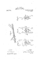
- Figure 1 1s a perspective new of a con crete reinforcement embodying my inven- .tion;
- Fig. 2 is a detail perspective view showing a modified form of the cent al shear members;
- Fig. 3 1s a cross section on line 111-111 Fig.1;
- Fig. 4 is a dctailpoispeca,
- tive viewof another form of shear members and l igs 5, 6 and 7 are sectional views showing different/forms of the main or tension bar of the reinforcement.
- My invention relates to the class of concrete reinforcements, and is designed to pro vide means of simple, novel' and efficient character for securing the shear members to the main or tension bar of the reinforcement; also to provide meansfor effectively increasing dissection of the intermediate portion of the main or tension barwhich is subjected to the greatest tensile stress without increasing the metal in the end portions of the bar, thereby providing for a maximum strength with a minimum amount of metal; and also to provide means of novel character for supporting the reinforcement in the forms or. molds in the process of construction.
- the numeral 2 designates the main or tension. bar of the reinforcement, which may be'of any approved cross-sectional form, such as the ellipse shown in Figs. 1 and 3 or the tllttll'lUlltl shown in Figs. 5, 6, and 7.
- This bar is provided at its upperside with a rib or flange 2-3, which is preferably continuous throughout the length of the bar, and which 13 sheen as of 'l'-shape in cross-section,
- the body portion of the bar may be, and is, preferably, provided vith suitable lateral. bonding projections or deformations 5.
- t3 designate the shear members, which preferably consist of loops of metal formed by bending rods of suitable cross section upon themselves to form parallel sided loopsclosed at their upper ends, the free ends of the rods being seated in the grooves 4 at each side of the rib or flange 3, and. so
- the shear members are pref erably extended through theclips or clamps, and are carried downwardly andbent in the direction of the longitudinalaxis of the bar 2 as shown at 8, for the purpose of forming means for supporting the reinforcing structure in the forms or molds in the process of. construction of thereinforce concrete work, whereby proper space for the concrete will be provided underneath the bars
- the upper ends of the looped shear members may be, if desired, given. quarter turns as shown at 9 in Fig. 4 to form eyes to receive the floor slab reinforcing rods 10.
- the shear members adjacent to the long-i tudi'nal center of the-bar 2 may be extended continuously from one to the other, asshown in Fig. 1, thereby providing for material reinforcement of the central portion of the bar 2 where the tensile stress is the greatest.
- the upper ends of these two central shear members may be closed as shown in Fig. l, or two separate rods may be employed as shown in Fig. 2 with their free ends left. disconnected.
- l1 designates a supplemental reinforcing bar, which may or may not be employed. ⁇ Vhen this bar is employed, it is preferably arranged as shown in Fig. 1, being extended. through the loops of the shear members, with its end portions bent obliquely upward as shown at 12, thence parallel with the bar 2 as shown at 13, for the purpose of resisting the tensile stress'caused by the neeative bending, moments over the point or support.
- the alntiliary reinforcing;- lirars'of adjacent reinforcing structures may be con' nectcd in any suitable manner, preferably by means of the'connecting links 1e shown in Fig. l. i v
- Fig. (i'shows a modified form of bar 'having only one lateral groove 15 to receive the end portion of a singleshear member 16.
- Fig. 7 shows another which the bar. has two ribs orflanges' 17, each ribor flange forming a groove 18 for a shear member.
- the shear members may be left substantially parallel with the bar 2 and bent upwardly into their normal oblique positions at the place where the reinforcing structure is to be used.
- main tension bars may be of other crosssections than those shown, they may be provided with any suitable bonding surfaces; the form of the clips or clam'ps which secure the shear members can be varied, and the shear members themselves may be con structed in different ways.
- Vhat I claim is 1.
- a metallic reinforcement for concrete comprising a main tension bar formed with opposite lateral grooves, looped shear members having portions lying longitudinally within the said grooves and clips engaging over the upper side of the bar and securmg the shear members in the grooves, and a supmodification in and floor slab reinforcing members passing-- throughsaid eyes in a direction substantially at right angles to the length of the tension members; substantially as described. 3.
- a metallic reinforcement for concrete having a main tension bar formed with lateral grooves, and shear members having longitudinally extending portions seated in said grooves and clips embracing said end por-, tions and securing them in said grooves, some of said shear members having portions extending continuously within said grooves between said members to form reinforcements for said bar, substantially as de-' scribed.
- a metallic reinforcement for concrete comprising a main tension. bar formed with opposite lateral grooves, and shear members having their lower end portions extending in the direction of said grooves and seated therein, together with separate clips having their end portions engaging with said grooves and securing the shear members .therein, some of said shear members having portlons.extending continuously within said grooves between said members to form reinforcements for said bar; substantially as described.-
- a metallic reinforcement for concrete comprising a main tension bar having longi tudinally extending grooves at opposite sides thereof, and shear members having portions extending in the direct-ion of said grooves and'seated and secured therein, and having their free lower ends bent backwardly underiieath the main tension bar to form support ing feet; substantially as described;
Landscapes
- Engineering & Computer Science (AREA)
- Architecture (AREA)
- Civil Engineering (AREA)
- Structural Engineering (AREA)
- Reinforcement Elements For Buildings (AREA)
Description
H. B. WHITE. GONURETE REINFORCEMENT. APPLICATION FILED DEC. 21; 190B.
atented @125, 191 0.
2 SFEETS-SEEET 1.
" rmvzmfon v @QXMML wemdke,
WITNESSES wmm ,HQ-ELWHITH CONCRETE REINFORCEMENT.
' APILIOATION FILED DEC. 21, 1908. I
, Patented Jan; 910.
2 sum HT 2.
LNVENTOR on? trim liliflthltil l r-lllllfi it" filth it till.
HERBERT E. WHITE, 01:" YOUNGSTOWN, O HID, ASSIGNOIB, TO THE GENERAL FIBEPROOF- ING COMPANY, OF NEW YORK, N. Y., COILPORATION OF OHIO.
,CONCRETE REINFORCEMENT.
cameo.
specification of Letters Patent. Patented Jan. Elfin, jttilffl.
Application filetl Dccemocr 21, 1908. Serial No. 468,4:16.
drawings, forming part of this specification,
in which.-
, Figure 1 1s a perspective new of a con crete reinforcement embodying my inven- .tion; Fig. 2 is a detail perspective view showing a modified form of the cent al shear members; Fig. 3 1s a cross section on line 111-111 Fig.1; Fig. 4 is a dctailpoispeca,
tive viewof another form of shear members and l igs 5, 6 and 7 are sectional views showing different/forms of the main or tension bar of the reinforcement.
My invention relates to the class of concrete reinforcements, and is designed to pro vide means of simple, novel' and efficient character for securing the shear members to the main or tension bar of the reinforcement; also to provide meansfor effectively increasing dissection of the intermediate portion of the main or tension barwhich is subjected to the greatest tensile stress without increasing the metal in the end portions of the bar, thereby providing for a maximum strength with a minimum amount of metal; and also to provide means of novel character for supporting the reinforcement in the forms or. molds in the process of construction.
The nature of my invention will be best understood by reference to the accompanying drawings in which I have shown the preferred embodiment thereof, and which will now be described, it being premised however that various changes may be made in the construction and arrangement of the parts by those skilled in the art without departing from the spirit and scope of my in vention as defined in the appended claims.
In these drawings the numeral 2 designates the main or tension. bar of the reinforcement, which may be'of any approved cross-sectional form, such as the ellipse shown in Figs. 1 and 3 or the tllttll'lUlltl shown in Figs. 5, 6, and 7. This bar is provided at its upperside with a rib or flange 2-3, which is preferably continuous throughout the length of the bar, and which 13 sheen as of 'l'-shape in cross-section,
the
thereby providing the lateral grooves at to receive the ends of the shear members in manner hereinafter described. The body portion of the bar may be, and is, preferably, provided vith suitable lateral. bonding projections or deformations 5.
t3 designate the shear members, which preferably consist of loops of metal formed by bending rods of suitable cross section upon themselves to form parallel sided loopsclosed at their upper ends, the free ends of the rods being seated in the grooves 4 at each side of the rib or flange 3, and. so
cured therein by means of the bent clips or clamps 'Z. One or both of the free ends of all or some of the shear members are pref erably extended through theclips or clamps, and are carried downwardly andbent in the direction of the longitudinalaxis of the bar 2 as shown at 8, for the purpose of forming means for supporting the reinforcing structure in the forms or molds in the process of. construction of thereinforce concrete work, whereby proper space for the concrete will be provided underneath the bars The upper ends of the looped shear members may be, if desired, given. quarter turns as shown at 9 in Fig. 4 to form eyes to receive the floor slab reinforcing rods 10. The shear members adjacent to the long-i tudi'nal center of the-bar 2 may be extended continuously from one to the other, asshown in Fig. 1, thereby providing for material reinforcement of the central portion of the bar 2 where the tensile stress is the greatest. The upper ends of these two central shear members may be closed as shown in Fig. l, or two separate rods may be employed as shown in Fig. 2 with their free ends left. disconnected.
l1 designates a supplemental reinforcing bar, which may or may not be employed. \Vhen this bar is employed, it is preferably arranged as shown in Fig. 1, being extended. through the loops of the shear members, with its end portions bent obliquely upward as shown at 12, thence parallel with the bar 2 as shown at 13, for the purpose of resisting the tensile stress'caused by the neeative bending, moments over the point or support. The alntiliary reinforcing;- lirars'of adjacent reinforcing structures may be con' nectcd in any suitable manner, preferably by means of the'connecting links 1e shown in Fig. l. i v
Fig. (i'shows a modified form of bar 'having only one lateral groove 15 to receive the end portion of a singleshear member 16.
Fig. 7 shows another which the bar. has two ribs orflanges' 17, each ribor flange forming a groove 18 for a shear member. i
The advantages of my invention result from theprovision of the simple and etlicient means for rigidly securing the shear members to the main or tension bar without the necessity for punching or otherwise perforating such bar, this being accomplished by means of clips or clamps of malleable metal, which can be readily bent to firmly grasp and secure the end portions of the shear members; from the manner in which the central shear members are constructed and arranged so as to form a material reinforcement of the central portion of the main or tension bar; from the" manner in which the shear members form a carrier or cradle for the auxiliary reinforcing bar, and also when desiredfor the floor slab reinforcing bars; and'also from the simple, practical construction of the structure as a whole, whereby a reinforcement is provided having a maximum strength with the use of a mlnimu1n amount of metal.
For convenience, in shipping the reinforce ing structures, the shear members may be left substantially parallel with the bar 2 and bent upwardly into their normal oblique positions at the place where the reinforcing structure is to be used.
It will be obvious that many changes can be made in the details of construction and arrangement without departing from the spirit and scope of my invention. Thus, the main tension bars may be of other crosssections than those shown, they may be provided with any suitable bonding surfaces; the form of the clips or clam'ps which secure the shear members can be varied, and the shear members themselves may be con structed in different ways.
Vhat I claim is 1. A metallic reinforcement for concrete, comprising a main tension bar formed with opposite lateral grooves, looped shear members having portions lying longitudinally within the said grooves and clips engaging over the upper side of the bar and securmg the shear members in the grooves, and a supmodification in and floor slab reinforcing members passing-- throughsaid eyes in a direction substantially at right angles to the length of the tension members; substantially as described. 3. A metallic reinforcement for concrete having a main tension bar formed with lateral grooves, and shear members having longitudinally extending portions seated in said grooves and clips embracing said end por-, tions and securing them in said grooves, some of said shear members having portions extending continuously within said grooves between said members to form reinforcements for said bar, substantially as de-' scribed.
4. A metallic reinforcement for concrete, comprising a main tension. bar formed with opposite lateral grooves, and shear members having their lower end portions extending in the direction of said grooves and seated therein, together with separate clips having their end portions engaging with said grooves and securing the shear members .therein, some of said shear members having portlons.extending continuously within said grooves between said members to form reinforcements for said bar; substantially as described.-
3. A metallic reinforcement for concrete, comprising a main tension bar having longi tudinally extending grooves at opposite sides thereof, and shear members having portions extending in the direct-ion of said grooves and'seated and secured therein, and having their free lower ends bent backwardly underiieath the main tension bar to form support ing feet; substantially as described;
In testimony whereof, I have hereunto set my hand. HERBER'E '\'v HITE.
W'itnesses: Geo. B. BLEMING,
GEORGE H. PARMELEE.
Priority Applications (1)
| Application Number | Priority Date | Filing Date | Title |
|---|---|---|---|
| US46841608A US947746A (en) | 1908-12-21 | 1908-12-21 | Concrete reinforcement. |
Applications Claiming Priority (1)
| Application Number | Priority Date | Filing Date | Title |
|---|---|---|---|
| US46841608A US947746A (en) | 1908-12-21 | 1908-12-21 | Concrete reinforcement. |
Publications (1)
| Publication Number | Publication Date |
|---|---|
| US947746A true US947746A (en) | 1910-01-25 |
Family
ID=3016164
Family Applications (1)
| Application Number | Title | Priority Date | Filing Date |
|---|---|---|---|
| US46841608A Expired - Lifetime US947746A (en) | 1908-12-21 | 1908-12-21 | Concrete reinforcement. |
Country Status (1)
| Country | Link |
|---|---|
| US (1) | US947746A (en) |
-
1908
- 1908-12-21 US US46841608A patent/US947746A/en not_active Expired - Lifetime
Similar Documents
| Publication | Publication Date | Title |
|---|---|---|
| KR101814754B1 (en) | Built-Up Beam | |
| US775927A (en) | Self-centering plate. | |
| US1317824A (en) | Reinforcing element fob | |
| US735759A (en) | Steel-concrete construction. | |
| US852202A (en) | Reinforced concrete arch. | |
| US893640A (en) | Reinforced girder. | |
| US756309A (en) | Reinforced beams, &c., and grillage therefor. | |
| US1273344A (en) | Concrete flooring construction. | |
| US742943A (en) | Fireproof girder or beam. | |
| US1233053A (en) | Secondary reinforcement for concrete structures. | |
| US845787A (en) | Metallic reinforcement in concrete structural work. | |
| US732482A (en) | Fireproof floor. | |
| US2347449A (en) | Reinforced concrete structure | |
| US763513A (en) | Fireproof ceiling. | |
| US925643A (en) | Shear-bar for reinforced concrete construction. | |
| US788570A (en) | Trestle. | |
| US994091A (en) | Reinforcement for concrete constructions. | |
| US904977A (en) | Tension-bar for concrete construction. | |
| US1087438A (en) | Reinforcement for concrete construction. | |
| US919273A (en) | Reinforcing-truss for concrete structures. | |
| US611907A (en) | hennebique | |
| US871568A (en) | Concrete-floor structure. | |
| US761288A (en) | Concrete-and-metal structure. | |
| US912219A (en) | Reinforced concrete structure. | |
| US1344929A (en) | Reinforced-concrete bridge structure |