US9477000B2 - System and method for the removal of shallow water multiples using a hybrid multi-channel prediction method - Google Patents
System and method for the removal of shallow water multiples using a hybrid multi-channel prediction method Download PDFInfo
- Publication number
- US9477000B2 US9477000B2 US14/107,583 US201314107583A US9477000B2 US 9477000 B2 US9477000 B2 US 9477000B2 US 201314107583 A US201314107583 A US 201314107583A US 9477000 B2 US9477000 B2 US 9477000B2
- Authority
- US
- United States
- Prior art keywords
- right arrow
- arrow over
- prediction operator
- model
- seismic
- Prior art date
- Legal status (The legal status is an assumption and is not a legal conclusion. Google has not performed a legal analysis and makes no representation as to the accuracy of the status listed.)
- Active, expires
Links
Images


Classifications
-
- G—PHYSICS
- G01—MEASURING; TESTING
- G01V—GEOPHYSICS; GRAVITATIONAL MEASUREMENTS; DETECTING MASSES OR OBJECTS; TAGS
- G01V1/00—Seismology; Seismic or acoustic prospecting or detecting
- G01V1/28—Processing seismic data, e.g. analysis, for interpretation, for correction
- G01V1/36—Effecting static or dynamic corrections on records, e.g. correcting spread; Correlating seismic signals; Eliminating effects of unwanted energy
- G01V1/362—Effecting static or dynamic corrections; Stacking
-
- G—PHYSICS
- G01—MEASURING; TESTING
- G01V—GEOPHYSICS; GRAVITATIONAL MEASUREMENTS; DETECTING MASSES OR OBJECTS; TAGS
- G01V1/00—Seismology; Seismic or acoustic prospecting or detecting
- G01V1/28—Processing seismic data, e.g. analysis, for interpretation, for correction
Definitions
- the present invention relates generally to underwater seismic exploration, and more specifically to systems and methods for the removal of shallow water multiples in processing data obtained from such exploration.
- Seismic waves generated artificially for the imaging of geological layers has been used for more than 50 years.
- the most widely used waves are by far reflected waves and more precisely reflected compressional waves, recorded by hydrophones and/or accelerometers.
- shear wave energy can also be of interest.
- vibrator equipment also known as a “source”
- sources generates a vibro-seismic signal that propagates in particular in the form of a wave that is reflected on interfaces of geological layers.
- These waves are received by geophones, or receivers, which convert the displacement of the ground resulting from the propagation of the waves into an electrical signal recorded by means of recording equipment. Analysis of the arrival times and amplitudes of these waves makes it possible to construct a representation of the geological layers on which the waves are reflected.
- a widely used technique for searching for oil or gas is the seismic exploration of subsurface geophysical structures.
- Reflection seismology is a method of geophysical exploration to determine the properties of a portion of a subsurface layer in the earth, which information is especially helpful in the oil and gas industry.
- Marine-based seismic data acquisition and processing techniques are used to generate a profile (image) of a geophysical structure (subsurface) of the strata underlying the seafloor. This profile does not necessarily provide an accurate location for oil and gas reservoirs, but it may suggest, to those trained in the field, the presence or absence of oil and/or gas reservoirs. Thus, providing an improved image of the subsurface in a shorter period of time is an on-going process.
- the seismic exploration process consists of generating seismic waves (i.e., sound waves) directed toward the subsurface area, gathering data on reflections of the generated seismic waves at interfaces between layers of the subsurface, and analysing the data to generate a profile (image) of the geophysical structure, i.e., the layers of the investigated subsurface.
- This type of seismic exploration can be used both on the subsurface of land areas and for exploring the subsurface of the ocean floor.
- Marine reflection seismology is based on the use of a controlled source that sends energy waves into the earth, by first generating the energy waves in or on the ocean. By measuring the time it takes for the reflections to come back to one or more receivers (usually very many, perhaps in the order of several dozen, or even hundreds), it is possible to estimate the depth and/or composition of the features causing such reflections. These features may be associated with subterranean hydrocarbon deposits.
- a data acquisition system 10 includes a ship 2 towing plural streamers 6 that may extend over kilometers behind ship 2 .
- Each of the streamers 6 can include one or more birds 13 that maintains streamer 6 in a known fixed position relative to other streamers 6 , and the birds 13 are capable of moving streamer 6 as desired according to bi-directional communications birds 13 can receive from ship 2 .
- One or more source arrays 4 a,b may be also towed by ship 2 or another ship for generating seismic waves. Source arrays 4 a,b can be placed either in front of or behind receivers 14 , or both behind and in front of receivers 14 .
- the seismic waves generated by source arrays 4 a,b propagate downward, reflect off of, and penetrate the seafloor, wherein the refracted waves eventually are reflected by one or more reflecting structures (not shown in FIG. 1 ) back to the surface (see, FIG. 2 , discussed below).
- the reflected seismic waves propagate upwardly and are detected by receivers 14 provided on streamers 6 . This process is generally referred to as “shooting” a particular seafloor area, and the seafloor area can be referred to as a “cell”.
- FIG. 2 illustrates a side view of the data acquisition system 10 of FIG. 1 .
- Ship 2 located on ocean surface 46 , tows one or more streamers 6 , that is comprised of cables 12 , and a plurality of receivers 14 .
- Shown in FIG. 2 are two source streamers, which include sources 4 a,b attached to respective cables 12 a,b .
- Each source 4 a,b is capable of transmitting a respective sound wave, or transmitted signal 20 a,b .
- transmitted signal 20 a For the sake of simplifying the drawings, but while not detracting at all from an understanding of the principles involved, only a first transmitted signal 20 a will be shown (even though some or all of source 4 can be simultaneously (or not) transmitting similar transmitted signals 20 ).
- First transmitted signal 20 a travels through ocean 40 and arrives at first refraction/reflection point 22 a .
- First reflected signal 24 a from first transmitted signal 20 a travels upward from ocean floor 42 , back to receivers 14 .
- a signal—optical or acoustical—travels from one medium with a first index of refraction n1 and meets with a different medium, with a second index of refraction n2 a portion of the transmitted signal is reflected at an angle equal to the incident angle (according to the well-known Snell's law), and a second portion of the transmitted signal can be refracted (again according to Snell's law).
- first transmitted signal 20 a generates first reflected signal 24 a , and first refracted signal 26 a .
- First refracted signal 26 a travels through sediment layer 16 (which can be generically referred to as first subsurface layer 16 ) beneath ocean floor 42 , and can now be considered to be a “new” transmitted signal, such that when it encounters a second medium at second refraction/reflection point 28 a , a second set of refracted and reflected signals 32 a and 30 a , are subsequently generated.
- the signals recorded by seismic receivers 14 vary in time, having energy peaks that may correspond to reflectors between layers. In reality, since the sea floor and the air/water are highly reflective, some of the peaks correspond to multiple reflections or spurious reflections that should be eliminated before the geophysical structure can be correctly imaged.
- Primary waves suffer only one reflection from an interface between layers of the subsurface (e.g., first reflected signal 24 a ). Waves other than primary waves are known as multiples, and more strictly, are events that have undergone more than one reflection.
- seismic source 4 produces first transmitted wave 20 a that splits into a primary transmitted wave 26 a (referred to also as first refracted signal) penetrating inside first subsurface layer 16 (referred to also as “sediment layer” though that does not necessarily need to be the case) under ocean floor 42 , and first reflected signal 24 a that becomes surface multiple signal 50 after it interfaces with ocean surface 46 (or fourth interface).
- Second transmitted wave 20 b is reflected once at second interface 48 and becomes second reflected signal 24 b , and then is reflected down again at ocean floor 42 to become internal multiple signal 51 .
- Internal multiple signal 51 and surface multiple signal 50 also reaches receiver 14 , but at different times.
- receiver 14 can receive at least several different signals from the same transmitting event: second reflected signal 30 a , surface multiple signal 50 , and internal multiple signal 51 .
- the timing of the received signals will depend on the depth of the ocean 40 , its temperature, density, and salinity, the depth of sediment layer 16 , and what it is made of.
- receiver 14 can become “confused” as to the true nature of the subsurface environment due to reflected signals 30 , and multiple signals 50 , 51 .
- other multiples can also be generated, some of which may also travel through the subsurface.
- a multiple therefore, is any signal that is not a primary reflected signal. Multiples, as is known by those of ordinary skill in the art, can cause problems with determining the true nature of the geology of the earth below the ocean floor. Multiples can be confused by data acquisition system 10 with first, second or third reflected signals.
- Internal multiple signals 51 typically arise due to a series of subsurface impedance contrasts. They are commonly observed in seismic data acquired in various places, such as the Santos Basin of Brazil. They are often poorly discriminated from the primaries (i.e., the first, second and third reflected signals, among others), because they have similar movement, dips and frequency bandwidth, thereby making attenuation and/or elimination of internal multiple signals 51 (as well as surface multiples 50 ) one of the key issues in providing clear seismic images in interpreting areas of interest. Over time, various methods have been developed to address this difficult problem and most of them rely on the ability to identify the multiple generators.
- SRME Surface-Related Multiples Elimination
- seismic sources are essentially impulsive (e.g., compressed air is suddenly allowed to expand).
- One of the most used sources is air guns.
- the air guns produce a high amount of acoustics energy over a short time.
- Such a source is towed by a vessel either at the water surface or at a certain depth.
- the acoustic waves from the air guns propagate in all directions.
- a typical frequency range of the acoustic waves emitted by the impulsive sources is between 6 and 300 Hz.
- the frequency content of the impulsive sources is not fully controllable and different sources are selected depending on the needs of a particular survey.
- the use of impulsive sources can pose certain safety and environmental concerns.
- the marine vibrator (or air gun) can also generally be referred to as a “source,” i.e., a source of the sound/energy waves that are transmitted and then reflected/refracted off the ocean floor and then received by one or more, usually dozens, of receivers.
- Marine vibrators (herein after referred to as “vibrators,” “marine vibrators,” and/or “seismic vibrators,” or more simply as “sources”) can be implemented in what are referred to as “towed arrays” of the plurality of sources and their receivers, wherein each towed array can include numerous vibrators, numerous receivers, and can include several or more groups of receivers, each on its own cables, with a corresponding source, again on its own cable.
- Systems and methods for their use have been produced for devices that can maintain these cables, for example, in relatively straight lines as they are being towed behind ships in the ocean.
- an entire industry has been created to explore the oceans for new deposits of hydrocarbons, and has been referred to as “reflection seismology.”
- Marine vibratory sources including hydraulically powered sources and sources employing piezoelectric or magneto-strictive material, have been used in marine operations.
- a marine vibrator generates a long tone with a varying frequency, i.e., a frequency sweep.
- This signal is applied to a moving port, e.g., a piston, which generates a corresponding seismic wave.
- Instantaneous pressure resulting from the movement of plural pistons corresponding to plural marine vibrators may be lower than that or an airgun array, but total acoustic energy transmitted by the marine vibrator may be similar to the energy of the airgun array due to the extended duration of the signal.
- such sources need a frequency sweep to achieve the required energy.
- a sweep is a sinusoid with a continuously variable frequency, and can be defined by its amplitude A(f), its begin and end frequency, and its sweep rate Sr(f).
- Target-oriented sweep design i.e., searching for a particular known type of hydrocarbon, in a particular known type of geological formation
- SNR Signal-to-Noise ratio
- the shallow water de-multiple (SWD) technique based on the concept of multichannel prediction for attenuating surface related short period multiples in shallow water (see, “Shallow Water Demultiple,” Hung, B., et al., ASEG, Expanded Abstracts, 1-4[2010]), is generally a robust method, but improvements can be made, especially in regard to the first few order of multiples generated by the seafloor (and any events just beneath the seafloor) when the seafloor is very shallow and hence its reflections are indistinct or in post-critical angle range.
- MWD model-based water-layer de-multiple
- An object of the embodiments is to substantially solve at least the problems and/or disadvantages discussed above, and to provide at least one or more of the advantages described below.
- a method for determining a shallow water multiples model, the method comprising (a) estimating a prediction operator by a shallow water demultiple (SWD) technique using acquired receiver seismic data, (b) generating a multi-channel water layer de-multiple (MWD) primary reflections model using acquired receiver seismic data, and (c) merging said SWD prediction operator with said MWD primary reflection model with said acquired receiver seismic data to determine the shallow water multiples model.
- SWD shallow water demultiple
- MWD multi-channel water layer de-multiple
- the step (b) of generating a MWD primary reflections model comprises (b1) estimating a travel time of the transmitted seismic wavelets from one or more sources to each of a plurality of receivers, and (b2) generating the MWD primary reflection model using the estimated travel time and Green's function.
- auto-picking is performed using one or more the following criteria: estimation of the time of the water bottom reflection event, amplitude, amplitude ratio, and neighbouring trace information.
- the step (b1) of estimating a travel time of the transmitted seismic wavelets from the one or more sources to each of the plurality of receivers comprises evaluating a second Green's function according to the following expression—
- k ⁇ c , where ⁇ is frequency, c is velocity, r is a distance from a first source to a first receiver, and H 0 (2) is a 0 th order Hankel function of the second kind, and further wherein the variable “kr” is equal to
- ⁇ c ⁇ r which is equal to ⁇ t, where t is the travel time, which is the same as distance r divided by velocity c.
- the step (c) of merging the SWD prediction operator with the MWD primary reflection model with acquired receiver data to determine a shallow water multiples model comprises (c1) merging the generated MWD primary reflection models with the SWD prediction operator to create a hybrid prediction operator and (c2) convoluting the hybrid prediction operator with the acquired receiver data to determine the shallow water multiples model.
- the step of (c1) merging the generated MWD primary reflections models with the SWD prediction operator to create a hybrid prediction operator comprises overlaying Green's function on top of the SWD prediction operator.
- a method for predicting a shallow water multiples model in seismic receiver data comprising (a) estimating a multi-channel prediction operator F by shallow water demultiple (SWD) technique, (b) generating a model of the Green's functions of the water layer primary reflections, (c) merging the generated water layer primary reflections model with the multi-channel prediction operator F to create a hybrid multi-channel prediction operator F H , and (d) convolving the hybrid multi-channel prediction operator F H with receiver data to determine the shallow water multiples model.
- SWD shallow water demultiple
- step (b) of generating a model of the Green's functions of the water layer primary reflections comprises (b1) estimating a travel time of the transmitted seismic wavelets from one or more sources to each of a plurality of receivers, and (b2) generating the model of the Green's functions of the water layer primary reflections using the estimated travel time and Green's function.
- step (b1) of estimating a travel time of the transmitted seismic wavelets from the one or more sources to each of the plurality of receivers comprises evaluating a second Green's function according to the following expression—
- k ⁇ c , where ⁇ is frequency, c is velocity, r is a distance from a first source to a first receiver, and H 0 (2) is a 0 th order Hankel function of the second kind, and further wherein the variable “kr” is equal to
- ⁇ c ⁇ r which is equal to ⁇ t, where t is the travel time, which is the same as distance r divided by velocity c.
- step (c) of merging the generated water layer primary reflections model F with the multi-channel prediction operator F to create a hybrid multi-channel prediction operator F H comprises overlaying Green's function on top of the prediction operator.
- the method further comprises (e) generating an output seismic wave signal of the GAI by subtracting the final multiples model from the received and stored seismic data, and (f) displaying the generated output seismic wave signal as representative of a floor of a shallow body of water environment.
- a method for determining shallow water multiples when seismically exploring a geographical area of interest under a body of water comprising (a) generating a series of underwater seismic wavelets by one or more sources, (b) acquiring seismic data from a plurality of receivers, and storing the seismic data, (c) estimating a multi-channel prediction operator F using a model of water layer related multiples with respect to the received and stored seismic data, (d) estimating a travel time of the transmitted seismic wavelets from the one or more sources to each of the plurality of receivers, (e) generating water layer primary reflections models using the estimated travel time and Green's function, (f) merging the generated water layer primary reflections models with the multi-channel prediction operator F to create a hybrid multi-channel prediction operator F H , and (g) convoluting the hybrid multi-channel prediction operator F H with the stored received data to determine a final multiples model.
- the method further comprises (h) generating an output seismic wave signal of the GAI by subtracting the final multiples model from the received and stored seismic data, and (i) displaying the generated output seismic wave signal as representative of a floor of a shallow body of water environment.
- SNR signal-to-noise ratio
- auto-picking is performed using one or more the following criteria: estimation of the time of the water bottom reflection event, amplitude, amplitude ratio, and neighbouring trace information.
- the step of (f) merging the generated water layer primary reflections models with the multi-channel prediction operator F to create a hybrid multi-channel prediction operator F H comprises overlaying the Green's function on top of the multichannel prediction operator F.
- the step of (d) estimating a travel time of the transmitted seismic wavelets from the one or more sources to each of the plurality of receivers comprises: evaluating a second Green's function according to the following expression—
- k ⁇ c , where ⁇ is frequency, c is velocity, r is a distance from a first source to a first receiver, and H 0 (2) is a 0 th order Hankel function of the second kind, and further wherein the variable “kr” is equal to
- a system for determining shallow water multiples when seismically exploring a geographical area of interest under a body of water, the system comprising a processor configured to estimate a multi-channel prediction operator F using a model of water layer related multiples with respect to received and stored seismic data, estimate a travel time of the transmitted seismic wavelets from the one or more sources to each of the plurality of receivers, generate a water layer primary reflections models using the estimated travel time and Green's function, merge the generated water layer primary reflections models with the multi-channel prediction operator F to create a hybrid multi-channel prediction operator F H , and convolute the hybrid multi-channel prediction operator F H with the stored received data to determine a final multiples model.
- the processor is further configured to generate an output seismic wave signal of the GAI by subtracting the final multiples model from the received and stored seismic data, and generate a display signal for a display to display the generated output seismic wave signal as representative of a floor of a shallow body of water environment.
- SNR signal-to-noise ratio
- auto-picking is performed by the processor using one or more the following criteria: estimation of the time of the water bottom reflection event, amplitude, amplitude ratio, and neighbouring trace information, and further wherein when the processor merges the generated water layer primary reflections models with the multi-channel prediction operator F to create a hybrid multi-channel prediction operator F H , the processor is further configured to overlay the Green's function on top of the multichannel prediction operator F.
- the processor when the processor estimates a travel time of the transmitted seismic wavelets from the one or more sources to each of the plurality of receivers, the processor is further configured to evaluate a second Green's function according to the following expression—
- k ⁇ c , where ⁇ is frequency, c is velocity, r is a distance from a first source to a first receiver, and H 0 (2) is a 0 th order Hankel function of the second kind, and further wherein the variable “kr” is equal to
- ⁇ c ⁇ r which is equal to ⁇ t, where t is the travel time, which is the same as distance r divided by velocity c.
- the system further comprises one or more sources configured to generate a series of underwater seismic wavelets, and a plurality of receivers configured to acquire seismic data resulting from the generated series of underwater seismic wavelets, and a memory configured to store the seismic data.
- FIG. 1 illustrates a top view of a data acquisition system for use in an underwater seismic gathering process
- FIGS. 2 and 3 illustrate a side view of the data acquisition system of FIG. 1 and pictorially represents transmitted, reflected, refracted and multiples sound waves;
- FIG. 4 illustrates a flow chart of a method for determining shallow water multiples using a hybrid multichannel prediction method according to an embodiment
- FIGS. 5A-5F illustrate operation of the method of FIG. 4 on synthetic data
- FIGS. 6A-6E illustrate operation of the method of FIG. 4 on data taken off a first section of coast of Australia;
- FIGS. 7A-7D illustrate operation of the method of FIG. 4 on data taken off a second section of coast of Australia;
- FIG. 8 illustrates a seismic data acquisition system suitable for use to implement a method for determining shallow water multiples using a hybrid multichannel prediction method according to an embodiment
- FIG. 9 illustrates a general method for seismic exploration according to an embodiment
- FIG. 10 illustrates a partial side view of another embodiment of the marine seismic exploration system shown in FIG. 1 , wherein a curved streamer profile is implemented according to an embodiment
- FIG. 11 illustrates a multi-level source for use with the marine seismic exploration system shown in FIG. 1 according to an embodiment
- FIGS. 12A through 12E illustrate a configuration of at least two streamers for use in the marine seismic exploration system shown in FIG. 1 ;
- FIG. 13 illustrates a tail-buoy for use with the marine seismic exploration system shown in FIG. 1 with a ballasted keel shown in the extended position;
- FIG. 14 illustrates a tail-buoy for use with the marine seismic exploration system shown in FIG. 1 with the ballasted keel shown in the retracted position.
- USB universal serial bus
- HSIC high speed interchip
- CE consumer electronics
- PC personal computer
- SoC system-on-chip
- UMTI+ USB transceiver macro-cell interface
- ULPI UTMI+ low pin count interface
- PHY physical transceiver
- PCB printed circuit board
- SNR signal-to-noise ratio
- SWD shallow water de-multiple
- WLRMs water-layer related multiples
- MWD model-based water-layer de-multiple
- SRME surface related multiple elimination
- FIG. 9 illustrates a general method for seismic exploration (method 900 ).
- Step 902 of method 900 involves positioning and surveying of the potential site for seismic exploration.
- step 904 a determination of what type of seismic energy source should be used, and then causing seismic signals to be transmitted. While method 900 applies equally to both marine and land seismic exploration systems, each will use different types of equipment, especially in generating seismic signals that are used to develop data about the Earth's subsurface geologic structure.
- step 906 data recording occurs. In a first part of this step, receivers 14 , 64 receive and most often digitize the data, and in a second part of the step 906 , the data is transferred to a recording station.
- step 908 data processing occurs. Data processing generally involves enormous amounts of computer processing resources, including the storage of vast amounts of data, multiple processors or computers running in parallel.
- step 910 data interpretation occurs and results can be displayed, sometimes in two-dimensional form, more often now in three dimensional form.
- Four dimensional data presentations (a 3D plot or graph, over time (the fourth dimension) are also possible, when needed to track the effects of other processes, for example.
- a hybrid approach that combines the strengths of SWD and model-based methods to substantially eliminate shallow water multiples from obtained data.
- a multichannel prediction operator estimated by SWD can be used as a substantially accurate kinematic representation of the seafloor reflection with a higher signal-to-noise ratio (SNR), allowing the travel time of the seafloor to be automatically estimated.
- SNR signal-to-noise ratio
- a general method can be summarized as first estimating the multi-channel prediction operator using the WLRMs in the received data. Then, stacking the operator is performed to improve the SNR of the seafloor reflection. An estimation is then performed of the travel time (from source to seafloor to receiver), which then allows modeling of Green's function of seafloor reflections. The output of Green's function is then merged with the statistical operator of the SWD technique, and that output (which can be referred to as a “hybrid multi-channel prediction operator”) is convoluted with the data obtained at the receiver to obtain the final multiple model, which is then subtracted from the original data to arrive at the true underground underwater seismic wave data.
- the underground underwater seismic wave data is a representation of, in this case, the underground geography under the water when the water is such that it is classified as being “shallow water” as discussed above.
- M is the multiple model (i.e., the desired output)
- ⁇ P is the primary response
- P is the acquired seismic data
- w is a source wavelet.
- the water bottom is the reflection of the transmitted seismic wave off the water floor, typically, a shallow water location.
- the method discussed herein auto-picks the water bottom event using one or more of the following criteria: estimation of the time of the water bottom reflection event; amplitude; amplitude ratios; and neighbouring trace information. Such means for auto-picking the water bottom event are known to those of skill in the art of the embodiments disclosed herein.
- the multiples model can be predicted using the one way version of the Kirchhoff integral (see, “One-way Version of the Kirchhoff Integral,” Geophysics, Berkhout, A. J., et al., 54(4), 460-467 [1989]) in the form of:
- Equation (4) does not suffer from spectral distortion because the indistinctly recorded seafloor event is now modelled in an automatic sense by the corresponding Green's function.
- the Green's function provides improved spectral clarity for at least the following reasons. Picking a definite time provides an improved and more accurate Green's function, which is, of course, an accurate general solution of the wave equation. Because the water bottom events can be considered as a smeared water bottom time, and consist of waves that occupy one wave length, picking one point in time provides an accurate time point upon which to “anchor” or base the results of the Green's function upon. Therefore, an accurate time point provides an accurate Green's function that provides an accurate solution that results in substantially little or no spectral distortion.
- the embodiments make use of the fact that the multichannel prediction operator F can contain more than one multiple generating event.
- SWD can model multiples with more than single periodicity.
- each of multiple generator generates a multiple at a certain periodicity. Therefore, a single periodicity corresponds to a single multiple generator. While there is no limit to the number of periodicities, in order for them to be considered shallow water multiples, the limitation is that they must be shallow, or the periodicity is short.
- the multichannel prediction operator F is also equivalent to the discrete directional derivative of Green's function. According to a further embodiment, therefore, the multichannel prediction operator F can be merged with the Green's function of seafloor reflections to form a hybrid multichannel prediction operator F H such that it compensates for the missing high dips of the original multichannel prediction operator F and contains more than the seafloor event as a multiples generating event, as was originally represented by Green's function. Skipping ahead briefly to FIG. 5 , high dips are best described as shown in FIG. 5E , which is discussed in greater detail below, in that the high dips are the ideal operator shown in FIG. 5E that is missing from FIG. 5D .
- a high dip can also be described as a characteristic of an event trace.
- the horizontal axis is distance and the vertical axis is time.
- Visual velocity is a descriptor of the trace event as it moves in distance over time.
- the trace event moves less in space or distance, and takes more time as it approaches the edges. Therefore, it has slow visual velocity.
- the event has slow visual velocity in that it move less in space or distance over a longer period of time, as indicated by the spreading out of the trace event.
- the absolute value of the tangent is high for high dips, which is the area near the edge of the trace event, as was discussed above.
- the method of SWD which is trying to solve an inversion problem, obtains FIG. 5D at its best, meaning that it is limited in both time and space.
- Method 400 begins with step 402 , wherein one or more sources 4 transmit a plurality of source wavelets 30 , as shown in FIG. 1 , above a geographical area of interest (GAI), especially in a shallow water environment.
- GAI geographical area of interest
- step 404 the transmitted wavelets 30 that have been reflected and refracted off ocean floor 42 and/or different layers 16 , as well as multiples 51 , are received by one or more receivers 14 , and then the data is stored, as seismic data, usually, but not restrictively, in digital form, in seismic data acquisition system 200 , as discussed in greater detail below, in regard to FIG. 8 .
- method 400 then proceeds to manipulate the seismic data in order to generate the multiples model.
- method 400 uses WLRMs to estimate a multichannel prediction operator F in regard to the received seismic data.
- time and offset truncation refers to the mathematical nature and features of the multichannel prediction operator F.
- the multichannel prediction operator F would always show what is seen in FIG. 5E , but instead all that is achieved is what is seen in FIG. 5D . That is, in FIG. 5D , the image is truncated in the vertical (time) sense, as well as being “offset” (i.e., horizontally truncated).
- the multichannel prediction operator F described previously can be more accurately described as a time and offset truncated multichannel prediction operator F.
- method 400 stacks the estimated multichannel prediction operator F to improve the signal-to-noise ratio (SNR) of the seafloor reflection.
- stacking of the multichannel prediction operator F includes alignment of, and summing of, the different values of the estimated multichannel prediction operator F.
- method 400 automatically estimates the travel time, and using this information, models the Green's function of seafloor reflections.
- estimation of the travel time includes evaluation of a slightly different embodiment of the Green's function that is dependent on time, as those of skill in the art can appreciate.
- the further embodiment of Green's function, shown as Equation 3′, for 2D wave equation is represented as:
- k ⁇ c , where ⁇ is frequency, c is velocity, r is the distance from source to receiver, and H 0 (2) is the 0 th order Hankel function of the second kind.
- the variable “kr” is equal to
- Equation 3 describe the Green's function from source to receiver, and can be decomposed into two parts; one is Green's function from source to water bottom, and the other is Green's function from water bottom to receiver. Equation 3′, however, according to an embodiment, describes how Green's function is evaluated for wave travel directly from one point to another point.
- step 412 in which the modelled Green's function determined in step 412 is merged with the multichannel prediction operator F determined in step 406 to form a hybrid multichannel prediction operator F H .
- the hybrid multichannel prediction operator F H overcomes the deficiencies of previously determined multichannel prediction operators in that it compensates for the missing high frequency information, can contains even more seafloor events, than that as represented by the Green's function.
- Green's function of the water layer reflection as embodied by Equation (2) provides a solution, however ideal, for a single event.
- the multichannel prediction operator F provides solutions for more than a single event, but none of them are ideal.
- merging of the modelled Green's function determined in step 412 with the multichannel prediction operator F determined in step 406 to determine the hybrid multichannel prediction operator F H is accomplished by overlaying the Green's function on top of multichannel prediction operator F, or, according to a further embodiment, reversing the overlay, i.e., overlaying the multichannel prediction operator F on top of Green's function
- step 414 method 400 , using Equation 4, performs a convolution of the hybrid multichannel prediction operator F H with the original seismic data, obtained in step 404 , to produce a final multiples model.
- method 400 proceeds to step 416 wherein sophisticated methods are used to subtract the multiples from the original seismic data to produce a substantially multiples free set of seismic data that accurately depicts the underground environment of the GAI in shallow water areas.
- methods of subtraction can include a least square adaptive subtraction, using an L1 or L2 norm, or curvelet domain adaptive subtraction, among other methods, as known to those of skill in the art.
- the embodiments described here provides for enhanced shallow water multiple determination and finds short period multiples with more than single periodicity without the need of manual picking the seafloor event.
- FIGS. 5A-5F illustrate operation of the method of FIG. 4 on synthetic data, and shows that the multichannel prediction operator estimated from WLRMs is equivalent to Green's function of shallow reflectors.
- FIG. 5A is the reflectivity model that was used to generate the synthetic data.
- FIG. 5B shows a shot gather that has the nearest offset of 250 m and a magnified section of the shallow part shown in FIG. 5C . There are three shallow reflectors, but the reflections showed in the magnified section are smeared together. The area highlighted by the black dashed line in FIG. 5B was used to estimate the multichannel prediction operator, which is shown in FIG. 5D ; note that all three shallow reflectors are reconstructed correctly.
- FIG. 5A is the reflectivity model that was used to generate the synthetic data.
- FIG. 5B shows a shot gather that has the nearest offset of 250 m and a magnified section of the shallow part shown in FIG. 5C . There are three shallow reflectors, but the reflections showed in the magnif
- FIG. 5E shows the Green's function of the seafloor reflections estimated by using the seafloor travel time information derived from FIG. 5D .
- FIG. 5F shows the hybrid multichannel prediction operator F H by merging the two operators shown in FIGS. 5D and 5E .
- the hybrid multichannel prediction operator F H has a better defined seafloor reflection in time and offset, and includes the other two events of FIG. 5D .
- the first event shown in FIGS. 5D and 5F i.e., the topmost trace event
- the only trace event shown in FIG. 5E are all seafloor reflections.
- the horizontal direction is spatial offset (with zero offset being at the center of the Figures), representing the distance between the source and receiver and the vertical direction is time.
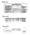
- FIGS. 6A-6E illustrate operation of the method of FIG. 4 on data taken off a first section of coast of Australia
- FIGS. 7A-7D illustrate operation of the method of FIG. 4 on data taken off a second section of coast of Australia.
- the first field data example is a line acquired offshore Australia.
- FIG. 2 a displays a near offset stack section.
- the presence of the reef gives rise to strong short-period free-surface multiples.
- the seafloor is at a depth of around 30 m in the middle of the line and the acquired nearest offset is 180 m, which makes the reflections in post-critical range even for the nearest offset. Consequently, the auto-correlation plot ( FIG. 6B ), a commonly used method for estimating the periodicity of the multiples, fails to reveal the travel time of the seafloor reflections. Hence, it is difficult, if not impossible; to identify the seafloor event for the calculation of its associated Green's function.
- the multichannel prediction operator F was estimated from the WLRMs (see FIG. 6C ). As can be observed, it is now much easier to pick the water bottom event because it is much better defined with enhanced S/N ratio. Dashed line A in FIG. 6C indicates the auto-picked result. With this travel time information, the Green's function of the seafloor reflections can then be modelled. The resulting Green's function and the operator F were then merged and convolved with the data for modelling of the multiples. FIG. 6D displays the multiple model obtained by this hybrid approach. Comparing FIG. 6D with the model in FIG. 6E , which was predicted by the SWD approach, it can be seen that the hybrid method has much less spectral distortion. It is evident that method 400 according to an embodiment overcomes the issue faced by SWD when the seafloor reflections are not properly recorded.
- FIG. 7A shows two common channel sections of the input data.
- FIGS. 7B and 7C display the multiple models obtained by the hybrid approach (left graph of the Figures) and SWD approach (right graph of the Figures), respectively.
- the adaptive subtraction results using the hybrid model are shown in FIG. 7D (left graph shown the hybrid approach and the right graph the SWD approach).
- the WLRMs are mostly attenuated by the hybrid method because the multiple model is much better defined.
- multichannel prediction operators estimated from water layer related multiples provides a good solution in modelling seafloor reflections when they are not distinctly recorded in seismic data.
- the multichannel prediction operator is a substantially accurate kinematic representation of the seafloor reflection and can be used for modelling the corresponding Green's function. Combining this Green's function with the multichannel prediction operator, it has been demonstrated that this hybrid approach provides superior performance in suppressing water layer related multiples for shallow water data in comparison with conventional means.
- FIG. 8 illustrates a seismic data acquisition system suitable for use in implementing method 400 for determining shallow water multiples using a hybrid multichannel prediction method according to an embodiment.
- FIG. 8 illustrates a seismic data acquisition system (system) 200 suitable for use to implement a method for determining shallow water multiples using a hybrid multichannel prediction method according to an embodiment.
- System 200 includes, among other items, server 201 , source/receiver interface 202 , internal data/communications bus (bus) 204 , processor(s) 208 (those of ordinary skill in the art can appreciate that in modern server systems, parallel processing is becoming increasingly prevalent, and whereas a single processor would have been used in the past to implement many or at least several functions, it is more common currently to have a single dedicated processor for certain functions (e.g., digital signal processors) and therefore could be several processors, acting in serial and/or parallel, as required by the specific application), universal serial bus (USB) port 210 , compact disk (CD)/digital video disk (DVD) read/write (R/W) drive 212 , floppy diskette drive 214 (though less used currently, many servers still include this device), and data storage unit 232 .
- Data storage unit 232 itself can comprise hard disk drive (HDD) 216 (these can include conventional magnetic storage media, but, as is becoming increasingly more prevalent, can include flash drive-type mass storage devices 224 , among other types), ROM device(s) 218 (these can include electrically erasable (EE) programmable ROM (EEPROM) devices, ultra-violet erasable PROM devices (UVPROMs), among other types), and random access memory (RAM) devices 220 .
- Usable with USB port 210 is flash drive device 224
- CD/DVD R/W device 212 are CD/DVD disks 234 (which can be both read and write-able).
- Usable with diskette drive device 214 are floppy diskettes 237 .
- Each of the memory storage devices, or the memory storage media can contain parts or components, or in its entirety, executable software programming code (software) 236 that can implement part or all of the portions of the method described herein.
- processor 208 itself can contain one or different types of memory storage devices (most probably, but not in a limiting manner, RAM memory storage media 220 ) that can store all or some of the components of software 236 .
- system 200 also comprises user console 234 , which can include keyboard 228 , display 226 , and mouse 230 . All of these components are known to those of ordinary skill in the art, and this description includes all known and future variants of these types of devices.
- Display 226 can be any type of known display or presentation screen, such as liquid crystal displays (LCDs), light emitting diode displays (LEDs), plasma displays, cathode ray tubes (CRTs), among others.
- User console 235 can include one or more user interface mechanisms such as a mouse, keyboard, microphone, touch pad, touch screen, voice-recognition system, among other inter-active inter-communicative devices.
- System 200 can further include communications satellite/global positioning system (GPS) transceiver device 238 , to which is electrically connected at least one antenna 240 (according to an embodiment, there would be at least one GPS receive-only antenna, and at least one separate satellite bi-directional communications antenna).
- GPS global positioning system
- System 200 can access internet 242 , either through a hard wired connection, via I/O interface 222 directly, or wirelessly via antenna 240 , and transceiver 238 .
- Server 201 can be coupled to other computing devices, such as those that operate or control the equipment of ship 2 , via one or more networks.
- Server 201 may be part of a larger network configuration as in a global area network (GAN) (e.g., internet 242 ), which ultimately allows connection to various landlines.
- GAN global area network
- system 200 being ostensibly designed for use in seismic exploration, will interface with one or more sources 4 a,b and one or more receivers 14 . These, as previously described, are attached to streamers 6 a,b , to which are also attached birds 13 a,b that are useful to maintain positioning. As further previously discussed, sources 4 and receivers 14 can communicate with server 201 either through an electrical cable that is part of streamer 6 , or via a wireless system that can communicate via antenna 240 and transceiver 238 (collectively described as communications conduit 246 ).
- user console 235 provides a means for personnel to enter commands and configuration into system 200 (e.g., via a keyboard, buttons, switches, touch screen and/or joy stick).
- Display device 226 can be used to show: streamer 6 position; visual representations of acquired data; source 4 and receiver 14 status information; survey information; and other information important to the seismic data acquisition process.
- Source and receiver interface unit 202 can receive the hydrophone seismic data from receiver 14 though streamer communication conduit 248 (discussed above) that can be part of streamer 6 , as well as streamer 6 position information from birds 13 ; the link is bi-directional so that commands can also be sent to birds 13 to maintain proper streamer positioning.
- Source and receiver interface unit 202 can also communicate bi-directionally with sources 4 through the streamer communication conduit 248 that can be part of streamer 6 . Excitation signals, control signals, output signals and status information related to source 4 can be exchanged by streamer communication conduit 248 between system 200 and source 4 .
- Bus 204 allows a data pathway for items such as: the transfer and storage of data that originate from either the source sensors or streamer receivers; for processor 208 to access stored data contained in data storage unit memory 232 ; for processor 208 to send information for visual display to display 226 ; or for the user to send commands to system operating programs/software 236 that might reside in either the processor 208 or the source and receiver interface unit 202 .
- System 200 can be used to implement method 400 for determining shallow water multiples using a hybrid multichannel prediction method according to an embodiment.
- Hardware, firmware, software, or a combination thereof, can be used to perform the various steps and operations described herein.
- software 236 for carrying out the above discussed steps can be stored and distributed on multi-media storage devices such as devices 216 , 218 , 220 , 224 , 234 , and/or 237 (described above) or other form of media capable of portably storing information (e.g., universal serial bus (USB) flash drive 224 ).
- USB universal serial bus
- streamers 6 that are towed by one or more vessels/ships 2 and the streamers 6 include seismic receivers/detectors 14 .
- the streamers 6 can be horizontal or slanted or having a curved profile as illustrated in FIG. 10 .
- the curved streamer 6 of FIG. 10 includes a body or cable 12 having a predetermined length; plural detectors 14 provided along the body 12 ; and plural birds 13 provided along body 12 for maintaining the selected curved profile.
- Curved streamer 6 is configured to flow underwater when towed such that the plurality of detectors 14 are distributed along the curved profile.
- the curved profile can also be described by as parameterized curve, e.g., a curve described by (i) a depth z 0 of a first detector 14 (measured from the water surface 46 ), (ii) a slope s 0 of a first portion T of body 12 with an axis 54 parallel with water surface 46 , and (iii) a predetermined horizontal distance h c between the first detector 14 a and an end of the curved profile.
- the curved profile should not be construed to always apply to the entire length of streamer 6 . While this situation is possible, the curved profile may be applied only to a first portion 56 of streamer 6 .
- streamer 6 can have (i) only a first portion 56 having the curved profile or (ii) a first portion 56 having the curved profile and a second portion 58 having a flat profile, the two portions being attached to each other.
- FIG. 11 illustrates multi-level source 60 for use with marine seismic exploration system 10 shown in FIG. 1 according to an embodiment.
- Multi-level source 60 has one or more sub-arrays 62 .
- the first sub-array 62 has a float 64 that is configured to float at the water surface 46 or underwater at a predetermined depth.
- Plural source points 66 a - d are suspended from the float 64 in a known manner.
- a first source point 66 a may be suspended closest to the head 64 a of the float 64 , at a first depth z 1 .
- a second source point 66 b may be suspended next, at a second depth z 2 , different from z 1 .
- a third source point 66 c may be suspended next, at a third depth z 3 , different from z 1 and z 2 , and so on.
- FIG. 11 shows, for simplicity, only four source points 66 a - d , but an actual implementation may have any desired number of source points 66 . In one application, because source points 66 can be distributed at different depths, the source points 66 at the different depths are not simultaneously activated.
- the source array is synchronized, i.e., a deeper source point 66 is activated later in time (e.g., 2 ms for 3 m depth difference when the speed of sound in water is 1500 m/s) such that corresponding sound signals produced by the plural source points 66 coalesce, and thus, the overall sound signal produced by the source array appears as being a single sound signal.
- the depths z 1 to z 4 of the source points of the first sub-array 62 can obey various relationships.
- the depths of source points 66 increase from head 64 a toward the tail 64 b of float 64 , i.e., z 1 ⁇ z 2 ⁇ z 3 ⁇ z 4
- the depths of source points 66 decrease from head 64 a to tail 64 b of float 66 .
- source points 66 are slanted, i.e., provided on an imaginary line 68 .
- line 68 is a straight line.
- line 68 is a curved line, e.g., part of a parabola, circle, hyperbola, etc.
- the depth of the first source point 66 a for the sub-array 62 is about 5 m and the largest depth of the last source point 66 d is about 8 m.
- the depth range is between about 8.5 and about 10.5 m or between about 11 and about 14 m.
- the depths of the source points 66 increase by 0.5 m from a first source point to an adjacent source point.
- these ranges are exemplary and these numbers may vary from survey to survey.
- a common feature of all these embodiments is that source points 66 have variable depths so that a single sub-array 62 exhibits multiple-level source points 66 .
- FIGS. 12A through 12E illustrate a configuration of at least two streamers 6 a , 6 b for use in the marine seismic exploration system 10 shown in FIG. 1 .
- a particular configuration of first and second streamers 6 a , 6 b are shown that illustrate several exemplary devices that assist in maintaining directional control and stability of streamers 6 in marine exploration system 10 .
- the devices include spread ropes 94 , that separate streamers 6 , bend restrictors 96 that join spread ropes 94 to streamers 6 , and spurline 98 , which connects streamer 6 b to 3-Eye splice 144 , which attaches to bridle block 150 and deflector 148 .
- At least one purpose of deflector 148 is to provide a force to said plurality of streamers 6 to maintain directional stability and control.
- a close up view of bridle block 150 is shown in FIG. 12E .
- a close up view of 3-Eye splice is shown in FIG. 12D .
- a close up view of bend restrictor 96 is shown in FIG. 12B .
- Head buoys 92 a , 92 b provide a visual indication of the location of streamers 6 , and they are connected to streamers 6 by restrictors 156 , a close up view of which is shown in FIG. 12C .
- FIG. 13 illustrates tail-buoy 100 for use with marine seismic exploration system 10 shown in FIG. 1 with ballasted keel 162 shown in the extended position
- FIG. 14 illustrates tail-buoy 100 for use with marine seismic exploration system 10 shown in FIG. 1 with ballasted keel shown 162 in the retracted position.
- the purpose of tail-buoy 100 is to (a) provide a visual indicator of the end of streamers 6 , and (b) to assist in maintaining directional stability and control of streamers 6 . This is especially true with Broadseis streamer configurations. In order to accomplish both functions, it is necessary to maintain directional control of tail-buoy 100 in much the same manner as is done with birds 13 .
- ballasted keel 162 with pitch and yaw stabilizers 160 , 158 have been added.
- Yaw stabilizer 158 comprises most of ballasted keel 162 , as it is shown to be the vertical component that can be controlled much in the same manner as a rudder for a boat.
- tail-buoy 100 when it is determined to have tail-buoy 100 turn to the left, directional controls are sent to it and received at navigation mast 154 (which contains power sources, signal processing circuitry, and so on, a detailed description of which has been omitted for the dual purposes of clarity and brevity), so that yaw stabilizer 158 turns to the left, causing the nose of tail-buoy 100 to swing to the left as water passes around yaw stabilizer 158 , as those of ordinary skill in the art can appreciate.
- navigation mast 154 which contains power sources, signal processing circuitry, and so on, a detailed description of which has been omitted for the dual purposes of clarity and brevity
- yaw stabilizer 158 turns to the left, causing the nose of tail-buoy 100 to swing to the left as water passes around yaw stabilizer 158 , as those of ordinary skill in the art can appreciate.
- the same general principles apply when it is desired to turn tail-buoy 100 to the right.
- Pitch stabilizer 160 assists in maintaining direction control in much the same manner, but is used to impart a down-ward or up-ward force on the body of tail-buoy 100 with respect to the surrounding water.
- pitch stabilizer 160 can be made fixed and not controllable by remote command.
- ballasted keel 164 can be stored in a retracted position, as shown in FIG. 14 .
- Additional motors, servos, and appropriate command and control circuitry can be provided to effectuate those functions, or the same can be accomplished manually, without additional circuitry and so on; when stored, ballasted keel 162 is folded up and a pin keeps in the retracted condition, and when placed in the water, the pin is removed, ballasted keel 162 folds down, the ballast drives ballasted keel 162 in the down position.
- these techniques can be applied in either an “offline”, e.g., at a land-based data processing center or an “online” manner, i.e., in near real time while on-board the seismic vessel.
- the system and method for determining shallow water multiples using a hybrid multichannel prediction method according to an embodiment can occur as the seismic data is recorded on-board the seismic vessel. In this case, it is possible for substantially multiples-free data to be generated as a measure of the quality of the sampling run.
- the various functional aspects of the embodiments may be embodied in a wireless communication device, a telecommunication network, as a method or in a computer program product. Accordingly, the embodiments may take the form of an entirely hardware embodiment or an embodiment combining hardware and software aspects. Further, the embodiments may take the form of a computer program product stored on a computer-readable storage medium having computer-readable instructions embodied in the medium. Any suitable computer-readable medium may be utilized, including hard disks, CD-ROMs, digital versatile discs (DVDs), optical storage devices, or magnetic storage devices such a floppy disk or magnetic tape. Other non-limiting examples of computer-readable media include flash-type memories or other known types of memories.
- Such programmable devices and/or other types of circuitry as previously discussed can include a processing unit, a system memory, and a system bus that couples various system components including the system memory to the processing unit.
- the system bus can be any of several types of bus structures including a memory bus or memory controller, a peripheral bus, and a local bus using any of a variety of bus architectures.
- various types of computer readable media can be used to store programmable instructions.
- Computer readable media can be any available media that can be accessed by the processing unit.
- computer readable media can comprise computer storage media and communication media.
- Computer storage media includes volatile and non-volatile as well as removable and non-removable media implemented in any method or technology for storage of information such as computer readable instructions, data structures, program modules or other data.
- Computer storage media includes, but is not limited to, RAM, ROM, EEPROM, flash memory or other memory technology, CDROM, digital versatile disks (DVD) or other optical disk storage, magnetic cassettes, magnetic tape, magnetic disk storage or other magnetic storage devices, or any other medium which can be used to store the desired information and which can be accessed by the processing unit.
- Communication media can embody computer readable instructions, data structures, program modules or other data in a modulated data signal such as a carrier wave or other transport mechanism and can include any suitable information delivery media.
- the system memory can include computer storage media in the form of volatile and/or non-volatile memory such as read only memory (ROM) and/or random access memory (RAM).
- ROM read only memory
- RAM random access memory
- a basic input/output system (BIOS) containing the basic routines that help to transfer information between elements connected to and between the processor, such as during start-up, can be stored in memory.
- BIOS basic input/output system
- the memory can also contain data and/or program modules that are immediately accessible to and/or presently being operated on by the processing unit.
- the memory can also include an operating system, application programs, other program modules, and program data.
- the processor can also include other removable/non-removable and volatile/non-volatile computer storage media.
- the processor can access a hard disk drive that reads from or writes to non-removable, non-volatile magnetic media, a magnetic disk drive that reads from or writes to a removable, non-volatile magnetic disk, and/or an optical disk drive that reads from or writes to a removable, non-volatile optical disk, such as a CD-ROM or other optical media.
- Other removable/non-removable, volatile/non-volatile computer storage media that can be used in the operating environment include, but are not limited to, magnetic tape cassettes, flash memory cards, digital versatile disks, digital video tape, solid state RAM, solid state ROM and the like.
- a hard disk drive can be connected to the system bus through a non-removable memory interface such as an interface, and a magnetic disk drive or optical disk drive can be connected to the system bus by a removable memory interface, such as an interface.
- the embodiments discussed herein can also be embodied as computer-readable codes on a computer-readable medium.
- the computer-readable medium can include a computer-readable recording medium and a computer-readable transmission medium.
- the computer-readable recording medium is any data storage device that can store data which can be thereafter read by a computer system. Examples of the computer-readable recording medium include read-only memory (ROM), random-access memory (RAM), CD-ROMs and generally optical data storage devices, magnetic tapes, flash drives, and floppy disks.
- the computer-readable recording medium can also be distributed over network coupled computer systems so that the computer-readable code is stored and executed in a distributed fashion.
- the computer-readable transmission medium can transmit carrier waves or signals (e.g., wired or wireless data transmission through the Internet). Also, functional programs, codes, and code segments to, when implemented in suitable electronic hardware, accomplish or support exercising certain elements of the appended claims can be readily construed by programmers skilled in the art to which the embodiments pertains.
- the disclosed embodiments provide a source array, computer software, and a method for determining shallow water multiples using a hybrid multichannel prediction method according to an embodiment. It should be understood that this description is not intended to limit the embodiments. On the contrary, the embodiments are intended to cover alternatives, modifications, and equivalents, which are included in the spirit and scope of the embodiments as defined by the appended claims. Further, in the detailed description of the embodiments, numerous specific details are set forth to provide a comprehensive understanding of the claimed embodiments. However, one skilled in the art would understand that various embodiments may be practiced without such specific details.
Abstract
Description
M=ΔPw −1 P and
M=FP,
wherein the SWD prediction operator F is equivalent to ΔP.
G(s,r;ω)=∫G(s,x;ω)F′(s,x,r)G(x,r;ω)dx,
where s and r are source and receiver locations, respectively, F′ is an auto-picked water bottom event from the multichannel prediction operator F at location x, and ω is frequency.
where ω is frequency, c is velocity, r is a distance from a first source to a first receiver, and H0 (2) is a 0th order Hankel function of the second kind, and further wherein the variable “kr” is equal to
which is equal to ω×t, where t is the travel time, which is the same as distance r divided by velocity c.
M=ΔPw −1 P and
M=FP,
wherein the multi-channel prediction operator F is equivalent to ΔP.
G(s,r;ω)=∫G(s,x;ω)F′(s,x,r)G(x,r;ω)dx,
where s and r are source and receiver locations, respectively, F′ is an auto-picked water bottom event from the multichannel prediction operator F at location x, and ω is frequency.
wherein j=√{square root over (−1)},
where ω is frequency, c is velocity, r is a distance from a first source to a first receiver, and H0 (2) is a 0th order Hankel function of the second kind, and further wherein the variable “kr” is equal to
which is equal to ω×t, where t is the travel time, which is the same as distance r divided by velocity c.
G(s,r;ω)=∫G(s,x;ω)F′(s,x,r)G(x,r;ω)dx,
where s and r are source and receiver locations, respectively, F′ is an auto-picked water bottom event from the multichannel prediction operator F at location x, and ω is frequency.
M=ΔPw −1 P and
M=FP,
and wherein the multichannel prediction operator F is equivalent to ΔP.
wherein j=√{square root over (−1)},
where ω is frequency, c is velocity, r is a distance from a first source to a first receiver, and H0 (2) is a 0th order Hankel function of the second kind, and further wherein the variable “kr” is equal to
which is equal to ω×u, where t is the travel time, which is the same as distance r divided by velocity c.
G(s,r;ω)=∫G(s,x;ω)F′(s,x,r)G(x,r;ω)dx,
where s and r are source and receiver locations, respectively, F′ is an auto-picked water bottom event from the multichannel prediction operator F at location x, and ω is frequency.
M=ΔPw −1 P and
M=FP,
and wherein the multichannel prediction operator F is equivalent to ΔP.
wherein j=√{square root over (−1)},
where ω is frequency, c is velocity, r is a distance from a first source to a first receiver, and H0 (2) is a 0th order Hankel function of the second kind, and further wherein the variable “kr” is equal to
which is equal to ω×t, where t is the travel time, which is the same as distance r divided by velocity c.
M=ΔPw −1 P (1)
M=FP;∥M−FP∥ min 2 (2),
where F is the time and offset truncated multichannel prediction operator, which can be estimated by minimizing the prediction error between seismic data P and multiple M.
G(s,r;ω)=∫G(s,x;ω)F′(s,x,r)G(x,r;ω)dx (3),
where s and r are source and receiver locations, respectively; F′ is the auto-picked water bottom event from the multichannel prediction operator F at location x, and ω is frequency. The water bottom is the reflection of the transmitted seismic wave off the water floor, typically, a shallow water location. The method discussed herein auto-picks the water bottom event using one or more of the following criteria: estimation of the time of the water bottom reflection event; amplitude; amplitude ratios; and neighbouring trace information. Such means for auto-picking the water bottom event are known to those of skill in the art of the embodiments disclosed herein.
wherein j=√{square root over (−1)}, and
where ω is frequency, c is velocity, r is the distance from source to receiver, and H0 (2) is the 0th order Hankel function of the second kind. The variable “kr” is equal to
which is equal to ω×t, where t is the travel time, which is the same as distance r divided by velocity c. According to an embodiment, the seismic wave used in
Claims (19)
M=ΔP w−1 P and
M=FP,
G({right arrow over (s)},{right arrow over (r)};ω)=∫G({right arrow over (s)},{right arrow over (r)};ω)F′({right arrow over (s)},{right arrow over (x)},R)G({right arrow over (X)},R;ω)d{right arrow over (x)}
M=ΔPw −1 P and
M=FP,
G({right arrow over (s)},{right arrow over (r)};ω)=∫G({right arrow over (s)},{right arrow over (x)};ω)F′({right arrow over (s)},{right arrow over (x)},r)G({right arrow over (x)},r ;ω)d{right arrow over (x)}
G({right arrow over (s)},{right arrow over (r)};ω)=∫G({right arrow over (s)},{right arrow over (x)};ω)F′({right arrow over (s)},{right arrow over (x)},r)G({right arrow over (x)},{right arrow over (s)};ω)d{right arrow over (x)}
Priority Applications (1)
| Application Number | Priority Date | Filing Date | Title |
|---|---|---|---|
| US14/107,583 US9477000B2 (en) | 2013-01-11 | 2013-12-16 | System and method for the removal of shallow water multiples using a hybrid multi-channel prediction method |
Applications Claiming Priority (2)
| Application Number | Priority Date | Filing Date | Title |
|---|---|---|---|
| US201361751573P | 2013-01-11 | 2013-01-11 | |
| US14/107,583 US9477000B2 (en) | 2013-01-11 | 2013-12-16 | System and method for the removal of shallow water multiples using a hybrid multi-channel prediction method |
Publications (2)
| Publication Number | Publication Date |
|---|---|
| US20140198613A1 US20140198613A1 (en) | 2014-07-17 |
| US9477000B2 true US9477000B2 (en) | 2016-10-25 |
Family
ID=49918552
Family Applications (1)
| Application Number | Title | Priority Date | Filing Date |
|---|---|---|---|
| US14/107,583 Active 2034-11-17 US9477000B2 (en) | 2013-01-11 | 2013-12-16 | System and method for the removal of shallow water multiples using a hybrid multi-channel prediction method |
Country Status (5)
| Country | Link |
|---|---|
| US (1) | US9477000B2 (en) |
| EP (1) | EP2755053A3 (en) |
| AU (1) | AU2014200094A1 (en) |
| CA (1) | CA2838711A1 (en) |
| SG (1) | SG2014001952A (en) |
Cited By (3)
| Publication number | Priority date | Publication date | Assignee | Title |
|---|---|---|---|---|
| US10914853B2 (en) | 2017-03-16 | 2021-02-09 | Saudi Arabian Oil Company | Continuous seismic reservoir monitoring using a common focus point method |
| US11268352B2 (en) | 2019-04-01 | 2022-03-08 | Saudi Arabian Oil Company | Controlling fluid volume variations of a reservoir under production |
| US11460595B2 (en) | 2019-04-18 | 2022-10-04 | Saudi Arabian Oil Company | Unified continuous seismic reservoir monitoring |
Families Citing this family (10)
| Publication number | Priority date | Publication date | Assignee | Title |
|---|---|---|---|---|
| AU2014201436A1 (en) * | 2013-03-22 | 2014-10-09 | Cgg Services Sa | System and method for interpolating seismic data |
| US10422906B2 (en) * | 2014-03-03 | 2019-09-24 | Westerngeco L.L.C. | Modeling and filtering coherent noise in seismic surveys |
| CN106228003B (en) * | 2016-07-19 | 2019-03-19 | 西北工业大学 | A kind of method and device determining accurate Green's function |
| WO2018071628A1 (en) * | 2016-10-13 | 2018-04-19 | Downunder Geosolutions (America) Llc | Method for the attenuation of multiple refelections in shallow water settings |
| CN107390261B (en) * | 2017-06-27 | 2019-02-12 | 中国地质大学(武汉) | Surface-related multiple and higher-order spectra method and system based on linear Bregman algorithm |
| CN110858000B (en) * | 2018-08-24 | 2021-07-02 | 中国石油天然气股份有限公司 | Seismic data reconstruction method and device, computer equipment and storage medium |
| CN112444846B (en) * | 2019-08-27 | 2023-11-28 | 中国石油天然气集团有限公司 | Shallow water layer influence optimization method and device in seismic data |
| CN113484908B (en) * | 2021-08-25 | 2023-07-14 | 成都理工大学 | Missing seismic data reconstruction method for deep learning network by combining partial convolution and attention mechanism |
| CN114418041B (en) * | 2022-03-31 | 2022-06-21 | 合肥工业大学 | Electronic tongue white spirit detection method based on IG-HSIC-SVM |
| CN115963565B (en) * | 2023-01-20 | 2023-06-16 | 中国地质大学(北京) | Seabed multiple attenuation method and device based on hyperbolic vector median filter |
Citations (7)
| Publication number | Priority date | Publication date | Assignee | Title |
|---|---|---|---|---|
| US6005916A (en) * | 1992-10-14 | 1999-12-21 | Techniscan, Inc. | Apparatus and method for imaging with wavefields using inverse scattering techniques |
| US20060084859A1 (en) * | 1995-06-22 | 2006-04-20 | Techniscan, Inc. | Apparatus and method for imaging objects with wavefields |
| US20070247163A1 (en) * | 2004-04-03 | 2007-10-25 | Tage Rosten | Electromagnetic Wavefield Analysis |
| US20080019215A1 (en) * | 2006-07-24 | 2008-01-24 | Robertsson Johan O A | Seismic data acquisition and source-side derivatives generation and application |
| US20090076389A1 (en) * | 2007-07-09 | 2009-03-19 | Yuanwei Jin | Imaging by time reversal beamforming |
| US20110046907A1 (en) * | 2007-11-21 | 2011-02-24 | University Of Manitoba | System and methods of improved tomography imaging |
| US20130242696A1 (en) * | 2010-12-01 | 2013-09-19 | Gert-Jan A. van Groenestijn | Primary estimation on obc data and deep tow streamer data |
-
2013
- 2013-12-16 US US14/107,583 patent/US9477000B2/en active Active
-
2014
- 2014-01-08 AU AU2014200094A patent/AU2014200094A1/en not_active Abandoned
- 2014-01-09 CA CA2838711A patent/CA2838711A1/en not_active Abandoned
- 2014-01-09 EP EP14150614.7A patent/EP2755053A3/en not_active Withdrawn
- 2014-01-10 SG SG2014001952A patent/SG2014001952A/en unknown
Patent Citations (7)
| Publication number | Priority date | Publication date | Assignee | Title |
|---|---|---|---|---|
| US6005916A (en) * | 1992-10-14 | 1999-12-21 | Techniscan, Inc. | Apparatus and method for imaging with wavefields using inverse scattering techniques |
| US20060084859A1 (en) * | 1995-06-22 | 2006-04-20 | Techniscan, Inc. | Apparatus and method for imaging objects with wavefields |
| US20070247163A1 (en) * | 2004-04-03 | 2007-10-25 | Tage Rosten | Electromagnetic Wavefield Analysis |
| US20080019215A1 (en) * | 2006-07-24 | 2008-01-24 | Robertsson Johan O A | Seismic data acquisition and source-side derivatives generation and application |
| US20090076389A1 (en) * | 2007-07-09 | 2009-03-19 | Yuanwei Jin | Imaging by time reversal beamforming |
| US20110046907A1 (en) * | 2007-11-21 | 2011-02-24 | University Of Manitoba | System and methods of improved tomography imaging |
| US20130242696A1 (en) * | 2010-12-01 | 2013-09-19 | Gert-Jan A. van Groenestijn | Primary estimation on obc data and deep tow streamer data |
Non-Patent Citations (9)
| Title |
|---|
| A. Pica et al., "3D Surface-Related Multiple Modeling, Principles and Results", SEG Houston 2005 Annual Meeting, Nov. 6-11, 2005, pp. 2080-2083. |
| A.J. Berkhout et al., "One-Way Versions of the Kirchhoff Integral", Geophysics, Apr. 1989, pp. 460-467, vol. 54, No. 4. |
| A.J. Berkhout et al., "Removal of Internal Multiples with the Common-Focus-Point (CFP) Approach: Part 1-Explanation of the Theory", Geophysics, May-Jun. 2005, pp. V45-V60, vol. 70, No. 3. |
| B. Hung et al., "Shallow Water Demultiple", ASEG 2010, Sydney, Australia, Aug. 22-26, 2010, pp. 1-4. |
| H. Jin et al., "Model-Based Water-Layer Demultiple (MWD) for Shallow Water: from Streamer to OBS", SEG Las Vegas 2012 Annual Meeting, Nov. 4-9, 2012, pp. 1-5. |
| Hargreaves, "Surface Multiple Attenuation in Shallow Water and in the Construction of Primaries from Multiples", SEG, New Orleans 2006 Annual Meeting Sep. 29-Oct. 4, 2006, pp. 2689-2693. * |
| J. Biersteker, "MAGIC: Shell's Surface Multiple Attenuation Technique", SEG International Exposition and Annual Meeting, San Antonio, Texas, Sep. 9-14, 2001. |
| N. Hargreaves, "Surface Multiple Attenuation in Shallow Water and the Construction of Primaries from Multiples", SEG, New Orleans 2006 Annual Meeting, Sep. 29-Oct. 4, 2006, pp. 2689-2693. |
| S. King et al., "Suppressing Nonphysical Relfections in Green's Function Estimates Using Source-Receiver Interferometry", Geophysics, Jan.-Feb. 2012, pp. Q15-Q25, vol. 77, No. 1. |
Cited By (3)
| Publication number | Priority date | Publication date | Assignee | Title |
|---|---|---|---|---|
| US10914853B2 (en) | 2017-03-16 | 2021-02-09 | Saudi Arabian Oil Company | Continuous seismic reservoir monitoring using a common focus point method |
| US11268352B2 (en) | 2019-04-01 | 2022-03-08 | Saudi Arabian Oil Company | Controlling fluid volume variations of a reservoir under production |
| US11460595B2 (en) | 2019-04-18 | 2022-10-04 | Saudi Arabian Oil Company | Unified continuous seismic reservoir monitoring |
Also Published As
| Publication number | Publication date |
|---|---|
| US20140198613A1 (en) | 2014-07-17 |
| AU2014200094A1 (en) | 2014-07-31 |
| CA2838711A1 (en) | 2014-07-11 |
| EP2755053A3 (en) | 2017-04-05 |
| SG2014001952A (en) | 2014-08-28 |
| EP2755053A2 (en) | 2014-07-16 |
Similar Documents
| Publication | Publication Date | Title |
|---|---|---|
| US9477000B2 (en) | System and method for the removal of shallow water multiples using a hybrid multi-channel prediction method | |
| AU2021200580B2 (en) | Seismic acquisition methods | |
| US20200183036A1 (en) | Seismic data processing including true-azimuth three-dimensional internal multiple attentuation without subsurface information | |
| CA2801531C (en) | Method and system for determining source signatures after source ghost removal | |
| GB2503325A (en) | Receiver-based ghost filter generation | |
| US20160139283A1 (en) | Seismic wavefield deghosting and noise attenuation | |
| US11609349B2 (en) | Determining properties of a subterranean formation using an acoustic wave equation with a reflectivity parameterization | |
| US9366775B2 (en) | Seismic data processing including internal multiple modeling without subsurface information | |
| US20200333485A1 (en) | Randomizing sweeps in a marine survey | |
| US20230305176A1 (en) | Determining properties of a subterranean formation using an acoustic wave equation with a reflectivity parameterization |
Legal Events
| Date | Code | Title | Description |
|---|---|---|---|
| AS | Assignment |
Owner name: CGG SERVICES SA, FRANCE Free format text: ASSIGNMENT OF ASSIGNORS INTEREST;ASSIGNORS:YANG, KUNLUN;HUNG, BARRY;REEL/FRAME:031807/0245 Effective date: 20131216 |
|
| FEPP | Fee payment procedure |
Free format text: PAYOR NUMBER ASSIGNED (ORIGINAL EVENT CODE: ASPN); ENTITY STATUS OF PATENT OWNER: LARGE ENTITY |
|
| STCF | Information on status: patent grant |
Free format text: PATENTED CASE |
|
| MAFP | Maintenance fee payment |
Free format text: PAYMENT OF MAINTENANCE FEE, 4TH YEAR, LARGE ENTITY (ORIGINAL EVENT CODE: M1551); ENTITY STATUS OF PATENT OWNER: LARGE ENTITY Year of fee payment: 4 |