US947657A - Drop-hammer. - Google Patents
Drop-hammer. Download PDFInfo
- Publication number
- US947657A US947657A US51080709A US1909510807A US947657A US 947657 A US947657 A US 947657A US 51080709 A US51080709 A US 51080709A US 1909510807 A US1909510807 A US 1909510807A US 947657 A US947657 A US 947657A
- Authority
- US
- United States
- Prior art keywords
- sleeve
- handle
- clamps
- clamp
- hammer
- Prior art date
- Legal status (The legal status is an assumption and is not a legal conclusion. Google has not performed a legal analysis and makes no representation as to the accuracy of the status listed.)
- Expired - Lifetime
Links
- 239000002023 wood Substances 0.000 description 1
Images
Classifications
-
- B—PERFORMING OPERATIONS; TRANSPORTING
- B21—MECHANICAL METAL-WORKING WITHOUT ESSENTIALLY REMOVING MATERIAL; PUNCHING METAL
- B21J—FORGING; HAMMERING; PRESSING METAL; RIVETING; FORGE FURNACES
- B21J7/00—Hammers; Forging machines with hammers or die jaws acting by impact
- B21J7/20—Drives for hammers; Transmission means therefor
- B21J7/36—Drives for hammers; Transmission means therefor for drop hammers
- B21J7/42—Drives for hammers; Transmission means therefor for drop hammers operated by rotary drive, e.g. electric motors
Definitions
- Patented J an. 25, i910..
- This invention aims to provide certain improvements in drop hammers, especially of the type shown for example in the patent of Stiles, No. 10,324, reissued May 8, 1888, in which the hammer is raised' by means of the friction of lifting rolls against a strap or bar of wood, and is lowered by releasing the strap from the rolls.
- This invention is directed particularly to improvements in the clamp frame or clamp mechanism by which the strap is held lifted after the lifting rolls have been withdrawn from it, and until the clamp is tripped by the operator.
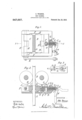
- Figure 1 is a. plan view partly in section;
- Fig. 2 is a vertical section approximately on the line 2-2 of Fig. l;
- Fig. 3 is an end elevation.
- the strap A carries the hammer at its lower end and is raised by frictional engagement with the rolls B. At its high point it is clamped between the pivoted clamps C and D.
- the clamps and connected mechanism are mounted upon a frame having a base E which rests on top of the side frame of the machine, and having sides F and a front wall G, the base of the frame being apertured for the passage of the strap A.
- a movable clamp C is mounted on an eccentric central portion H of a shaft M, the end portions J of which are journaled in the side walls F of the frame, and upon one end of which is keyed an arm K, the free end of which is connected by a rod L to the mechanism below by which it is actuated.
- the opposite clamp D is fixed in use, but is adjustable toward and from the movable clamp C. It is mounted on a shaft hl the intermediate portion of which passes through a projecting portion N of a bracket O which is clamped upon the base E of the frame by means of a bolt P which passes through an elongated slot Q in the base, and has its head held in an oblong recess R on the under side of the base.
- the bracket O and clamp l By turning the nut S on the upper end of this bolt, the bracket O and clamp l) may be held rigidly in position, the nut being slightly unscrewed to permit adjustment of the bracket and clamp; or the nut may be screwed up so tightly as to hold the clamp lirmly in place against the strains of use, while at the same time permitting a slight. adjustmentby the mechanism hereinafter described.
- a threaded rod T pinned at its inner end to the bracket and projecting into an internally threaded sleeve ll which is fitted rotatively in an opening through the front wall or flange of the frame, being held against outward movement by a collar V lying in a recess in the inner side of the wall G.
- the internally threaded sleeve or nut U is turned by a handle TV which is permanently attached and is adapted in one position to be rotated relatively to the sleeve, and in another position to turn the sleeve to effect the required adjustments.
- the desired conneetion is made by means of a fork X which is swiveled within the end of the sleeve U and projects outwardly therefrom, and in the outer end of which the handle or lever W is transversely pivoted.
- the lever l is provided with a portion Y so positioned that when the lever is bent relatively to its fork, the portion Y will enter one or another of a number of notches Z in the end face of the sleeve U.
- a fork a is provided at a fixed point on the end wall G of the frame in position to receive the end of the lever WT when the latter is bent, and to hold the same by means of a pin b so as to prevent rotation of the threaded sleeve.
- a pair of clamps, and means for adjusting one of said clamps toward the other comprising a non-rotative threaded rod, an internally threaded sleeve engaging said rod, and a handle attached to said sleeve with a swivel joint to permit it to be turned to dili'erent positions relatively to said sleeve, and means for bringing said handle in engagement with said sleeve to permit the turning ot' the. sleeve by the handle.
- a pair of clamps, and means for adjusting one of said clamps toward the other comprising a non-rotative threaded rod, an. internally threaded sleeve engaging said rod, and a handle attached to said sleeve with a swivel joint to permit it to be turned to different positions relatively to said sleeve, means for bringing said handle in engagement with said sleeve topermit the turning of the sleeve by the handle, and means for fastening said handle when in such engagel ment with the sleeve so as to prevent the turning of the handle.
- a pair of clamps in combination, a pair of clamps, a base E earrying said clamps, a bracket attached to one of said clamps, a threaded rod T non rotatably attached to said bracket, a rotatable sleeve U threaded on said rod T and held against longitudinal movement relatively to said base, and means for turning said sleeve.
- a pair of clamps and means for adjusting one ot' said clamps toward the other including a non-rotative threaded rod T, a rotatable sleeve U threaded on said rod T, a swivel fork X in the end ot said sleeve U, a handle IY pivoted in said toi-LY and having a portion Y, said sleeve ll being provided with notches Z in whieh said portion Y is adapted to enter when the handle is' bent but Jfrom which said portions Y are free when the handle is straight.
Landscapes
- Engineering & Computer Science (AREA)
- Mechanical Engineering (AREA)
- Clamps And Clips (AREA)
Description
' o. WERNER. DROP HAMMER.
APPLIGATIUN FILED AUG. v2, 1909.
Patented Ja11.25,1910.
WITNEssE-S f r 'ieri' ummm OTTO WERNER, OF NEW YORK, N. Y., ASSIGNOR TO E. W. BLISS COMPANY, OF
BROOKLYN, NEW YORK, A CORPORATION OF WEST VIRGINIA.
DROP-HAMMER.
Specification of Letters Patent.
Patented J an. 25, i910..
Application filed August 2, 1909. Serial No. 510,807.
To all whom 'it may concern:
Be it known that I, O'rro VVnnNnn, a citizen of the United States, residing in the borough of Brooklyn, county of Kings, city and State of New York, have invented certain new and useful 'Improvements in Dropl-lammers, of which the following is a specication.
This invention aims to provide certain improvements in drop hammers, especially of the type shown for example in the patent of Stiles, No. 10,324, reissued May 8, 1888, in which the hammer is raised' by means of the friction of lifting rolls against a strap or bar of wood, and is lowered by releasing the strap from the rolls.
This invention is directed particularly to improvements in the clamp frame or clamp mechanism by which the strap is held lifted after the lifting rolls have been withdrawn from it, and until the clamp is tripped by the operator.
The accompanying drawings illustrate an embodiment of the invention.
Figure 1 is a. plan view partly in section; Fig. 2 is a vertical section approximately on the line 2-2 of Fig. l; Fig. 3 is an end elevation.
Referring to the embodiment of the invention illustrated, the strap A carries the hammer at its lower end and is raised by frictional engagement with the rolls B. At its high point it is clamped between the pivoted clamps C and D. The clamps and connected mechanism are mounted upon a frame having a base E which rests on top of the side frame of the machine, and having sides F and a front wall G, the base of the frame being apertured for the passage of the strap A. A movable clamp C is mounted on an eccentric central portion H of a shaft M, the end portions J of which are journaled in the side walls F of the frame, and upon one end of which is keyed an arm K, the free end of which is connected by a rod L to the mechanism below by which it is actuated. When the strap is to be clamped the movable clamp C is thrown inward by turning the eccentric in one direction. When the strapl is to be released, the same clamp C is moved outward by a reversal of the eccentric. The opposite clamp D is fixed in use, but is adjustable toward and from the movable clamp C. It is mounted on a shaft hl the intermediate portion of which passes through a projecting portion N of a bracket O which is clamped upon the base E of the frame by means of a bolt P which passes through an elongated slot Q in the base, and has its head held in an oblong recess R on the under side of the base. By turning the nut S on the upper end of this bolt, the bracket O and clamp l) may be held rigidly in position, the nut being slightly unscrewed to permit adjustment of the bracket and clamp; or the nut may be screwed up so tightly as to hold the clamp lirmly in place against the strains of use, while at the same time permitting a slight. adjustmentby the mechanism hereinafter described.
For effecting the movement of the bracket U, there is provided a threaded rod T, pinned at its inner end to the bracket and projecting into an internally threaded sleeve ll which is fitted rotatively in an opening through the front wall or flange of the frame, being held against outward movement by a collar V lying in a recess in the inner side of the wall G.
The internally threaded sleeve or nut U is turned by a handle TV which is permanently attached and is adapted in one position to be rotated relatively to the sleeve, and in another position to turn the sleeve to effect the required adjustments. The desired conneetion is made by means of a fork X which is swiveled within the end of the sleeve U and projects outwardly therefrom, and in the outer end of which the handle or lever W is transversely pivoted. The lever l is provided with a portion Y so positioned that when the lever is bent relatively to its fork, the portion Y will enter one or another of a number of notches Z in the end face of the sleeve U. Thus in the position shown in full lines in Fig. 2 the lever is engaged with the sleeve U in such a way as to turn it and adjust the bracket and clamp; while in the dotted line position the lever may be swung freely with its swivel fork X without turning the sleeve.
Preferably a fork a is provided at a fixed point on the end wall G of the frame in position to receive the end of the lever WT when the latter is bent, and to hold the same by means of a pin b so as to prevent rotation of the threaded sleeve.
An adjustment will be effected by removing the pin l), swinging the lever W out to the straight position, and turning@A it and swinging it in again to the bent position engaging another of the notches Z, and then turning the handle back and fastening it in the fork a.
I claim as my invention l. In a machine of the class described, a pair of clamps, and means for adjusting one of said clamps toward the other comprising a non-rotative threaded rod, an internally threaded sleeve engaging said rod, and a handle attached to said sleeve with a swivel joint to permit it to be turned to dili'erent positions relatively to said sleeve, and means for bringing said handle in engagement with said sleeve to permit the turning ot' the. sleeve by the handle.
2. In a machine of the class described, a pair of clamps, and means for adjusting one of said clamps toward the other comprising a non-rotative threaded rod, an. internally threaded sleeve engaging said rod, and a handle attached to said sleeve with a swivel joint to permit it to be turned to different positions relatively to said sleeve, means for bringing said handle in engagement with said sleeve topermit the turning of the sleeve by the handle, and means for fastening said handle when in such engagel ment with the sleeve so as to prevent the turning of the handle. A
In a machine of the class described, in combination, a pair of clamps, a base E earrying said clamps, a bracket attached to one of said clamps, a threaded rod T non rotatably attached to said bracket, a rotatable sleeve U threaded on said rod T and held against longitudinal movement relatively to said base, and means for turning said sleeve.
et. In a machine ot' the class deseribed, in combination, a pair of clamps and means for adjusting one ot' said clamps toward the other including a non-rotative threaded rod T, a rotatable sleeve U threaded on said rod T, a swivel fork X in the end ot said sleeve U, a handle IY pivoted in said toi-LY and having a portion Y, said sleeve ll being provided with notches Z in whieh said portion Y is adapted to enter when the handle is' bent but Jfrom which said portions Y are free when the handle is straight.
In witness whereof, .l have hereunto signed my name in the presence ot tivo snliscribing witnesses.
OTT() \Vlllll\'lllt.
Witnesses H. F. HUGUES, F. C. FLADD.
Priority Applications (1)
| Application Number | Priority Date | Filing Date | Title |
|---|---|---|---|
| US51080709A US947657A (en) | 1909-08-02 | 1909-08-02 | Drop-hammer. |
Applications Claiming Priority (1)
| Application Number | Priority Date | Filing Date | Title |
|---|---|---|---|
| US51080709A US947657A (en) | 1909-08-02 | 1909-08-02 | Drop-hammer. |
Publications (1)
| Publication Number | Publication Date |
|---|---|
| US947657A true US947657A (en) | 1910-01-25 |
Family
ID=3016075
Family Applications (1)
| Application Number | Title | Priority Date | Filing Date |
|---|---|---|---|
| US51080709A Expired - Lifetime US947657A (en) | 1909-08-02 | 1909-08-02 | Drop-hammer. |
Country Status (1)
| Country | Link |
|---|---|
| US (1) | US947657A (en) |
-
1909
- 1909-08-02 US US51080709A patent/US947657A/en not_active Expired - Lifetime
Similar Documents
| Publication | Publication Date | Title |
|---|---|---|
| US1509022A (en) | Clamp | |
| US1117917A (en) | Drill-holder. | |
| US2605156A (en) | Self-locking mechanism for tilting top drafting tables | |
| US1975695A (en) | Wrench | |
| US1045146A (en) | Pinionv-pullin g mechanism | |
| US1319987A (en) | Pipe-bending machine | |
| US1825431A (en) | Feeding mechanism | |
| US1393789A (en) | Mandrel-press | |
| US2321911A (en) | Adjustable clamp | |
| US1054665A (en) | Chain pipe-vise or the like. | |
| US651413A (en) | Switch-rod. | |
| US1629602A (en) | Rolling-mill screw-down | |
| US966943A (en) | Wrench. | |
| US2137113A (en) | Work clamp | |
| US715851A (en) | Wood-calipers. | |
| US2895202A (en) | Yoke-type clamps | |
| US1671445A (en) | Meat block and clamp | |
| US906164A (en) | Gage. | |
| US1515646A (en) | Slub catcher | |
| US1131923A (en) | Gage. | |
| US2895203A (en) | Yoke-type clamps | |
| US762784A (en) | Wrench. | |
| US828055A (en) | Machine for capping bottles. | |
| US1373648A (en) | Self-adjusting caster | |
| US1133492A (en) | Extension-frame for mining-drills. |