US947299A - Target-throwing device. - Google Patents
Target-throwing device. Download PDFInfo
- Publication number
- US947299A US947299A US49026209A US1909490262A US947299A US 947299 A US947299 A US 947299A US 49026209 A US49026209 A US 49026209A US 1909490262 A US1909490262 A US 1909490262A US 947299 A US947299 A US 947299A
- Authority
- US
- United States
- Prior art keywords
- target
- arm
- trap
- rod
- conveyer
- Prior art date
- Legal status (The legal status is an assumption and is not a legal conclusion. Google has not performed a legal analysis and makes no representation as to the accuracy of the status listed.)
- Expired - Lifetime
Links
Images



Classifications
-
- F—MECHANICAL ENGINEERING; LIGHTING; HEATING; WEAPONS; BLASTING
- F41—WEAPONS
- F41J—TARGETS; TARGET RANGES; BULLET CATCHERS
- F41J9/00—Moving targets, i.e. moving when fired at
- F41J9/16—Clay-pigeon targets; Clay-disc targets
- F41J9/18—Traps or throwing-apparatus therefor
- F41J9/32—Traps or throwing-apparatus therefor characterised by means for obviating the anticipation of the flight path
Definitions
- WITNESSES H i Wm. INVENTOH AITOR/VEV L. A. FRIDELL.
- WITNESSES INVENTOR f L W-S, fizz/QM.
- This shaft- carries a pulley improvements in traps for throwing targets, 7, for a purpose hereinafter setforth, andis and more particularly to that class of such partially incased by a sleeve .8 which is devices, which are used for throwing targets adapted to revolve thereon.
- the object of the invention is to provide a wheelll, the purposes of which will be set 7 a device of the character described which will forth hereinafter, and may be made to roautomatically project the targets, to be shot" tate with the shaft 3 by means of a clutchat, into the air at either regular or irregular -mechanism presently to be described; This intervals, and which will, at the same time, clutch is surrounded byac'asing 12, which project each target into the air at a different serves as a drive wheel, and which also proelevation from that of the one immediately tects the operative mechanism of the clutch. preceding or following it.
- This casing is integral with the sleeve 8 and
- all of the paraphernalia as carries a rod 13, extending diametrically well as the operative mechanism of the trap therethrough, and having limited longitudiis located behind the marksman, which nal play therein.
- One.end of this rod is feature is a great improvement over thenormally made to project through the case traps now in common use.
- ing by means of spring 14;, and to protrude
- a further feature resides in the provision into an aperture 15 in the surrounding band of novel means for manually operating the 16, which surrounds said casing and is supmechanism of the device. ported; from the main supporting frame.
- the rod 13 carries toggle levers 17 and'18, provide adevice of the character described, pivotally connected thereto, at one end. that will be simple yet efficient, and also one
- the lever 17 is hinged, at its other end, to that will be easily constructed, operated, and the end plate of casing 12 and lever 18 is kept in repair. hinged. at its other end to a circular plate 19
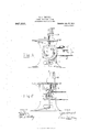
- Fig. 2 is a side elevation of the trap By a downward pressure upon the rod 20, operative means.
- Fig. 3 is a plan view of the same is brought into contact with rod the trap proper.
- Fig. 4 is a rear view of the 13 which is, inturn, forced downward and trap operative means.
- Fig. 5 is a side out of aperture 15.
- Fig. 6 is a sectional 17 and 18 operate to force plate 19 in a lati th e f taken on the line aa of Fig. 2. oral direction, and against wheel 82, rigidly Fig. 7 is an enlarged sectional View of the mounted on shaft 3, which wheel is, in turn, 0 trap taken on the line 6-6 of Fig. 1. 1 1g. forced against the frictional surface 22 car- 8 is a front elevation of the trap.
- Fig. 9 is ried by the inner end plate of casing 12. a plan view of the hopper looking from By reason of the contact ofthc wheel 82with beneath.
- the pulleys 9 and 10 are integral with sleeve 8 and rotate therewith, and together with two similar and similarly arranged pulleys 23 support endless cables 25 and 26, Which in turn support conveyers 27. These conveyers carry a sprocket chain 28 which is secured thereto by rivets or in some other suitable manner, and which engages with the sprocket wheel 11. This wheel, 11, is also integral with sleeve 3 and serves to drive the conveyors 27.
- Mounted upon the top member 29, of the supporting frame is a hopper 30.
- This hopper is spring mounted, being held suspended by means of the springs 31, on either sidethereof. These springs are secured to the top member 29 at one end and to the hopper at the other. By means of these springs the hopper is held suspended above the conveyors 27.
- Links 32 Pivoted to either side of the hopper are links 32 which extend downwardly and carry inwardly extending studs 33. These studs project into the eccentric grooves 3 1 in pulleys 9 and 10. These pulleys rotate in the direction indicated by the arrow in Fig. 5 and the studs 33 rest against the inner faces of the rims 67 carried by said pulleys and surrounding the grooves above referred to. The inner faces of these rims gradually approach the center of the pulleys 9 and 10 and by the rotation of said pulleys the hopper 30 is gradually lowerd through links 32. The downward pull upon the hopper is continued until studs 33 reach the shoulders of the said rims when said studs are released from said shoulders and the hopper is elevated by the tension of springs 31.
- the bottom, or discharge, of the hopper 30 is controlled by the two arcuate members 36 and 37.
- the member 36 is pivoted at the point 38 and its free end is provided with an outwardly extending arm 39 against which one of the links 32 rests.
- the member 37 is pivoted at the point 410 and carries rearwardly extending arm 41 against which the other link 32 rests.
- Tension springs 42 and 43 are attached to members 36 and 37, respectively, and tend to draw them together and restrict the discharge opening of the hopper. Vhen the studs 33 are released from the shoulders they come into contact with projections 4st protruding from the faces of the shoulders cameo and are thereby given a rearward throw.
- This rearward movement is communicated to links 32 and through them to the arms 39 and T1 of the members 36 and 37, and the tension of springs 12 and 43 thereby over come.
- the arcuate members 36 and 37 are forced apart and the hopper discharge enlarged and one of the targets, with which said hopper is filled, is allowed to drop to the conveyer 27.
- This conveyor is provided with platforms so located on said convcyer, with reference to one another, that a platform is directly under the hopper-3O and ready to receive a target when one is released.
- the trap shown in Figs. 1 and 3 is provided with a supporting base to.
- This arm rotates with its shaft and carries, at its free end fingers 51 and 52, pivoted thereto and capable of being opened and closed.
- the fingers are designed to grasp the targets, carried by the platform, and are nor mally held closed by the tension of spring
- the linger 51 is provided with a rubber roller (at, which enables the fingers to retain their grip on the target until the same is released in the manner, hereinafter described.
- a cord 57 is attached to the other end of said spring and passes around standard 58, projecting upward from the shaft 49, and is attached to an arm 59 extending upward from the trap stand stT.
- the standard 58 is provided with a rib (30, as shown in Figs.
- the shaft 19 carries a collar 61, integral therewith, which has an under surface whose plane cuts the shaft if) at an angle, which is not a right angle, and which rests upon a collar 62 carried by the rear end of a rocking arm (33.
- the upper face of collar (32 corresponds in shape and inclination to the under face of collar 61 and closely eontacts therewith, both of these faces declining rearwardly.
- the shaft 49 is provided with a ball and socket joint at the point where the plane of these inclined faces out said shaft.
- the target holder 5l,-52 is never higher, in relation to the conveyor, than the position shown in Fig. 1, and consequently any variation of said target holder must be downward.
- the position of the target holder t l-52, as shown in 51, enables it to receive the targets from the conveyer and if said target holder should be lower than the position shown in Fig. 1 it will still be in a position to grasp the target, as the same is grasped just as the platform on which it rests begins to descend be tween pulleys 23 and 2st.
- the variation of the elevation of said target holder is not sufficient, when the device is properly connected, to throw it out of position to take the target.
- a catch 64 (in the rear side of shaft +l9 a catch 64 is attached.
- a coil spring 65 is secured to this catch and after passing to one side of tie shaft. is secured also, to the forward end of the rocking arm 63. The tension of this spring operates to revolve the shaft i9 onehalf of the way around and to cause the arm 50 to perform a semi-circular sweep.
- the rocking arm 63 at its extreme forward end, carries a rolling support 68 which designed to move back andforth on an arcuate track (39, having an irregular sur-' face.
- This rolling support 68 is capable of longitudinal adjustment upon its supporting arm, by-reason of the slot 70 in which it is secured, and may be moved forward so that it will have a smooth arcuate track 71 on which to move.
- the drivewheel continues its revolution, and by so doing draws the rod 75 rearwardly.
- the front end of this rod '75 is attached to a cord 77 which passes around a pulleyTS, carried by the shaft 49, and the rearward movement of rod 75, through the operation of said cord and pulley, revolves the shaft 4-9 and causes the throw arm 50 to revolve over its former path in reverse direction to that of its former movement and to assume its original position, ready to receive the next
- the arm assumes its Original position, as shown in Fig. 3, the
- spring 56 is again drawn tense, by cord 57, and the fingers 51 and 52 drawn open to receive the target, which has been carried forward by conveyer 57.
- the mechanism is so adjusted that a target will be released, onto the conveyer, from the hopper, just as one is discharged from the arm 50, and as the said arm is brought back into position to be locked by trigger 66, the conveyer is forced forward through the operation of sprocket wheel 11 and a target, so released, carried forward till it comes within the reach of fingers 51 and 52.
- the rod 13 engages in the aperture 15, the clutch is disengaged, the revolution of drive wheel 12 ceases, the trigger 66 is engaged with arm 50 and the trap is again set ready to be sprung.
- the ratchet wheel 81 may be constantly turned, through the cable 72, as hereinbefore set out, or it may be turned either at regu lar, or irregular intervals, through the action of rod rigidly attached to the rod 75.
- This rod 80 carries at its forward end a dog 83, adapted to engage with the ratchet teeth of wheel 81, as said rod 80 moves rearwardly, and turn the same.
- the ratchet wheel is turned by the rod 80 and its dog 83 the cable 72 should be disengaged from the pulley carried by said ratchet wheel.
- hat I claim is 1.
- a target throwing device the combination with a trap and an operative mechanism therefor; of a means for locking said trap against the tension of the said operative mechanism; means for releasing said locking means; a means located in the rear of said trap for conveying the targets within the reach of said trap and means for operating said conveying means.
- a target throwing device the combination with a trap and a supporting frame therefor; of an operative mechani m for said trap; a means for locking said trap against the operation of said mechanism; means for releasing said locking means; a
- a trap comprising a supporting frame; a rotatable arm carried thereby; a means carried by said arm for engaging a target; means for controlling said engaging means; means for causing the rotation of said arm, means for varying the plane of said rotation in relation to the supporting frame, and means for varying the elevation of the point of discharge of the target from the trap in relation to said supporting frame.
- a trap comprising a supporting frame and a rotatable arm mounted thereon; means carried by said arm for engaging a target; means carried by said arm for securing said engagement; means for releasing said securing means; means for causing the rotation of said arm; means for locking said arm against rotation; means for releasing said locking means, means for varying the elevation of the point of discharge of the target in relation to the supporting frame and means for varying the lateral point of discharge of the target.
- ia trap comprising a supporting frame; a
- discharging means carried thereby; means carried by said discharging means for engaging a target; means for controlling said engaging means; means for causing the operation of said discharging means; means for varying the plane of movement of said discharging means in relation to the supporting fame and means for varying the lateral point of discharge of the target.
- a trap comprising a supporting frame; a discharging means carried thereby; means carried by said discharging means for engaging a target; means for controlling said engaging means; means for causing the operation of said discharging means; means for varying the plane of movement of said discharging means in relation to the supporting frame, and means for varying the point of discharge, of said target, from said discharging means.
- a means for operating said device comprising a supporting frame; a drive shaft carried there bv; a rotatable sleeve adapted to rotate with the shaft; a plurality of driving members carried by the sleeve, and a clutch whereby said drive shaft and said rotatable sleeve may be forced to rotate together, and by the disengagement of which the said sleeve and driving members will remain idle,independent of the rotation of said shaft all in com- 1 bination with a conveyer, driven by said operative means; a target receptacle arranged to discharge upon said conveyer; and means for causing the discharge of the targets upon the conveyer.
- a target throwing device the combination with a means for operating said device; of a conveyer, driven by said operative means; a target receptacle arranged to dis charge upon said conveyer; and means for causing the discharge of the targets upon the conveyer.
- a support a driving member carried thereby; a rotatable sleeve adapted to be engaged and rotate with said driving member, by means of a clutch comprising a power transmitting means, toggle levers attached thereto, a friction surface carried by said sleeve, a friction wheel carried by said driving member, one of said toggle levers being attached to a support, stationary with respect to the said sleeve, and the other of said levers being attached to a means for forcing said friction wheel against said friction surface, I
- said toggle levers being so secured to their respective attachments as to force said friction wheel against said friction surface, whereby said driving member and said rotatable sleeve are forced to rotate together.
- a target throwing device the combination with a means for operating said device; of a conveyer, driven by said operative means; a target receptacle arranged to discharge upon said conveyer; means for causing the discharge of the target upon the conveyer; a trap; operative mechanism therefor; means for locking said trap against the operation of said mechanism; means for releasing said locking means; and means for varying the point of discharge of thetargets from said trap.
- a target throwing device the combination, with a means for operating said device, of a conveyer driven by said operative means; a target receptacle arranged. to discharge upon said conveyer; means for causing the discharge of the target upon the conveyer; a trap; and an operative mechanism therefo; a means for locking said trap against the tension of said operative mechanism; means for releasing said locking means; said conveyer being so disposed as to conveythe targets Within the reach of said trap.
Landscapes
- Engineering & Computer Science (AREA)
- General Engineering & Computer Science (AREA)
- Catching Or Destruction (AREA)
Description
L. A. FRIDELL.
TARGET THROWING DEVICE.
APPLICATION FILED APR. 10, 1909.
Patented Jan.25, 1910.
4 SHEETS-SHEET 1.
WITNESSES:
Y L. A. FRIDELL. TARGET THROWING DEVICE.
APPLIOATION FILED APR.16, 1909.
947,299. Patented Jan. 25, 1910.
4 sums-4mm 2.
' hwwunulli m.
WITNESSES: H i Wm. INVENTOH AITOR/VEV L. A. FRIDELL.
TARGET THROWING DEVICE.
APPLICATION FILED APR. 16, 1909.
Patentd Jan. 25,1910.
4 SHEETS-SHEET 3.
INVENTOR 13-11 5 a Arr 31mm Louis, Q/ V'a e/Z L. A. FRIDELL.
TARGET THROWING- DEVICE.
APPLICATION FILED APR.16, 1909.
947,299, I Patented Jan.25, 1910.
4 sHBTs-sHEBT 4.
WITNESSES: INVENTOR f L W-S, fizz/QM.
munsw. enmun co. 9mm Lnnonmpuzns. HASHZKZI'N u M LOUIS A. FRIDELL, OF HOUSTON, TEXAS.
TARGET-.THROWING DEVICE.
f7,299. Specification of LettcrsPatent.
Application filed. April 16, 1909.
Patented Jan. 25, 1910.
Serial No. 490,262.
nected therewith. After the rod 13 passes To all whom it may concern: figures, the numerals 1 and 2 designate, re-
Be it known that I, LoUIs A. FRIDELL, a spectively, the side members of the support citizen of the United States, residing at ing frame of the trap operative means. Houston, in the county of Harris and State These side members support a transverse of Texas, have invented certain new and use crankshaft This shaft carries a fly-Wheel ful Improvements in Target-Throwing De- 4 and serves as the main drive shaftlof the vices, of which the following is a specificaoperative mechanism. It is manually opertion. ated by means of a foot. pedal 5 acting My invention relates to new and useful through link 6. This shaft-carries a pulley improvements in traps for throwing targets, 7, for a purpose hereinafter setforth, andis and more particularly to that class of such partially incased by a sleeve .8 which is devices, which are used for throwing targets adapted to revolve thereon. This sleeve car-, for marksmen. ries pulleyst) and 10., as well as sprocket The object of the invention is to provide a wheelll, the purposes of which will be set 7 a device of the character described which will forth hereinafter, and may be made to roautomatically project the targets, to be shot" tate with the shaft 3 by means of a clutchat, into the air at either regular or irregular -mechanism presently to be described; This intervals, and which will, at the same time, clutch is surrounded byac'asing 12, which project each target into the air at a different serves as a drive wheel, and which also proelevation from that of the one immediately tects the operative mechanism of the clutch. preceding or following it. This casing is integral with the sleeve 8 and In my device, all of the paraphernalia, as carries a rod 13, extending diametrically well as the operative mechanism of the trap therethrough, and having limited longitudiis located behind the marksman, which nal play therein. One.end of this rod is feature is a great improvement over thenormally made to project through the case traps now in common use. ing, by means of spring 14;, and to protrude A further feature resides in the provision into an aperture 15 in the surrounding band of novel means for manually operating the 16, which surrounds said casing and is supmechanism of the device. ported; from the main supporting frame. Finally the object of the invention is to The rod 13 carries toggle levers 17 and'18, provide adevice of the character described, pivotally connected thereto, at one end. that will be simple yet efficient, and also one The lever 17 is hinged, at its other end, to that will be easily constructed, operated, and the end plate of casing 12 and lever 18 is kept in repair. hinged. at its other end to a circular plate 19 With the above and other objects in view, j closely fitting within the casing and adapted my invention has particular relation to certo slide laterally, back and forth therein. tain novel features of construction and A foot operated rod 20, supported by the operation an example of which is given in main supporting frame, extends through the the following specification, and illustrated in aperture 15 and is, normally, in alinement 5 the accompanying drawings, wherein with rod 13, but is held withdrawn from Figure 1 is a side elevation of the trap contact therewith by means of spring 21. proper. Fig. 2 is a side elevation of the trap By a downward pressure upon the rod 20, operative means. Fig. 3 is a plan view of the same is brought into contact with rod the trap proper. Fig. 4 is a rear view of the 13 which is, inturn, forced downward and trap operative means. Fig. 5 is a side out of aperture 15. By reason of the downelevation of the operative means taken on ward pressure upon rod 13 the toggle levers the line az-m of Fig. 4. Fig. 6 is a sectional 17 and 18 operate to force plate 19 in a lati th e f taken on the line aa of Fig. 2. oral direction, and against wheel 82, rigidly Fig. 7 is an enlarged sectional View of the mounted on shaft 3, which wheel is, in turn, 0 trap taken on the line 6-6 of Fig. 1. 1 1g. forced against the frictional surface 22 car- 8 is a front elevation of the trap. Fig. 9 is ried by the inner end plate of casing 12. a plan view of the hopper looking from By reason of the contact ofthc wheel 82with beneath. said friction surface the casing, and sleeve Referring, now, more particularly to the 8, connected therewith'are forced to rotate 5 drawings, wherein like numerals of referwith said wheeland the shaft 3 rigidly con ence designate similar parts in each of the from the point of actuation by rod 20 itis held depressed by reason of its contact with band 16 and the clutch is thus held in engagement. This rotation continues for one revolution of the casing, when the free end of the rod 13 again comes into alinement with aperture 15 into which it is forced to project by the action of spring 14, whereby the clutch is again disengaged and the easing is held against further rotation.
The pulleys 9 and 10 are integral with sleeve 8 and rotate therewith, and together with two similar and similarly arranged pulleys 23 support endless cables 25 and 26, Which in turn support conveyers 27. These conveyers carry a sprocket chain 28 which is secured thereto by rivets or in some other suitable manner, and which engages with the sprocket wheel 11. This wheel, 11, is also integral with sleeve 3 and serves to drive the conveyors 27. Mounted upon the top member 29, of the supporting frame is a hopper 30. This hopper is spring mounted, being held suspended by means of the springs 31, on either sidethereof. These springs are secured to the top member 29 at one end and to the hopper at the other. By means of these springs the hopper is held suspended above the conveyors 27.
Pivoted to either side of the hopper are links 32 which extend downwardly and carry inwardly extending studs 33. These studs project into the eccentric grooves 3 1 in pulleys 9 and 10. These pulleys rotate in the direction indicated by the arrow in Fig. 5 and the studs 33 rest against the inner faces of the rims 67 carried by said pulleys and surrounding the grooves above referred to. The inner faces of these rims gradually approach the center of the pulleys 9 and 10 and by the rotation of said pulleys the hopper 30 is gradually lowerd through links 32. The downward pull upon the hopper is continued until studs 33 reach the shoulders of the said rims when said studs are released from said shoulders and the hopper is elevated by the tension of springs 31. It is obvious that the vertical play of the hopper is limited by the height of shoulders The bottom, or discharge, of the hopper 30 is controlled by the two arcuate members 36 and 37. The member 36 is pivoted at the point 38 and its free end is provided with an outwardly extending arm 39 against which one of the links 32 rests. The member 37 is pivoted at the point 410 and carries rearwardly extending arm 41 against which the other link 32 rests. Tension springs 42 and 43 are attached to members 36 and 37, respectively, and tend to draw them together and restrict the discharge opening of the hopper. Vhen the studs 33 are released from the shoulders they come into contact with projections 4st protruding from the faces of the shoulders cameo and are thereby given a rearward throw. This rearward movement is communicated to links 32 and through them to the arms 39 and T1 of the members 36 and 37, and the tension of springs 12 and 43 thereby over come. Thus the arcuate members 36 and 37 are forced apart and the hopper discharge enlarged and one of the targets, with which said hopper is filled, is allowed to drop to the conveyer 27. This conveyor is provided with platforms so located on said convcyer, with reference to one another, that a platform is directly under the hopper-3O and ready to receive a target when one is released.
The trap, shown in Figs. 1 and 3 is provided with a supporting base to. A trap stand 1 7, shown in detail in Figs. 7 and 8, is secured to this l ase in any suitable manner, and carries a collar 18 in which an upright shaft 19 rotates. To the upper extremity of this shaft an arm 50 is mounted. This arm rotates with its shaft and carries, at its free end fingers 51 and 52, pivoted thereto and capable of being opened and closed. The fingers are designed to grasp the targets, carried by the platform, and are nor mally held closed by the tension of spring The linger 51 is provided with a rubber roller (at, which enables the fingers to retain their grip on the target until the same is released in the manner, hereinafter described. These fingers are pivoted to the arm 50 at the point 55 but extend beyond said point, and to said extension the coil spring 56 is attached. A cord 57 is attached to the other end of said spring and passes around standard 58, projecting upward from the shaft 49, and is attached to an arm 59 extending upward from the trap stand stT. The standard 58 is provided with a rib (30, as shown in Figs. 1 and 3, around which this cord passes, and which causes the same to be drawn tense, when arm 50 is in the position shown in those figures; but when said arm swings around until it is at a right angle to the position shown, the cord 57 and spring 56 become lax and the fingers are released to the tension of spring 53--the only object of the spring 56 and cord 57 being to hold the fingers open until the target has been carried between them by the conveyer.
The shaft 19 carries a collar 61, integral therewith, which has an under surface whose plane cuts the shaft if) at an angle, which is not a right angle, and which rests upon a collar 62 carried by the rear end of a rocking arm (33. The upper face of collar (32 corresponds in shape and inclination to the under face of collar 61 and closely eontacts therewith, both of these faces declining rearwardly. The shaft 49 is provided with a ball and socket joint at the point where the plane of these inclined faces out said shaft. By reason of this construction it is obvious that the free end of the arm 50 will be elevated as it performs its forward sweep, and will reach its greatest point of elevation at the end of said sweep. The ball and socket joint above referred to is shown in detail in Fig. 7. The target holder 5l,-52 is never higher, in relation to the conveyor, than the position shown in Fig. 1, and consequently any variation of said target holder must be downward. The position of the target holder t l-52, as shown in 51, enables it to receive the targets from the conveyer and if said target holder should be lower than the position shown in Fig. 1 it will still be in a position to grasp the target, as the same is grasped just as the platform on which it rests begins to descend be tween pulleys 23 and 2st. The variation of the elevation of said target holder, is not sufficient, when the device is properly connected, to throw it out of position to take the target.
(in the rear side of shaft +l9 a catch 64 is attached. A coil spring 65 is secured to this catch and after passing to one side of tie shaft. is secured also, to the forward end of the rocking arm 63. The tension of this spring operates to revolve the shaft i9 onehalf of the way around and to cause the arm 50 to perform a semi-circular sweep. A. trigger (3G, normally holds the arm 50 against the rotation which the spring 65 tends to produce. This trigger is pivoted to its support, at a point intermediate the ends thereof, and its lower end carries a collar through which the rod 75 operates.
The rocking arm 63, at its extreme forward end, carries a rolling support 68 which designed to move back andforth on an arcuate track (39, having an irregular sur-' face. The movement of this arm, taken .in connection with the irregularity of the track 9 gives an irregular movement to the collar 62 and makes the elevation of thefree end of the arm 50, at the timeof. the discharge of the target uncertain. This rolling support 68 is capable of longitudinal adjustment upon its supporting arm, by-reason of the slot 70 in which it is secured, and may be moved forward so that it will have a smooth arcuate track 71 on which to move. The irregularity of the movement of arm 50 will thus be lessened when the rolling support plays on the smooth surface of the track 71, but will not be entirely obviated, as its motion will still be rendered irregir lar, by reason of the inclined contacting faces of collars G1 and 62, the ball and socket joint of shaft 49 and the constant rotation of collar 62, caused by the movement of the rocking arm 63. For the purpose of im parting said movement to said arm 63, I have provided a ratchet wheel 81. This wheel is constantly rotatedby means of an; endless cable 72, which is ,drivenflby pulley man will be unable to the conveyer.
is held in place by intermediate pulleys 73 and 74. The movement of this ratchet wheel is communicated to saidarm 63 through a link 84, attached to said wheel and arm.
TV hen the machine is in the position shown inFigs. 1' and 2 and a downward pressure is exerted on the rod 20 the clutch is engaged and the casing 12 is started, which imparts a'slight forward thrust to rod 75. This rod is given a slight forward thrust because the point of attachment of said rod to said casing is so located .as not to quite reach the dead center line, when the casing stops, and upon starting said rod is forced forward until said line is reached. This rod carries a collar 7 6 which is so positioned as-to be resting against the lower end of the trigger 66 when the casing starts. This collar is carried forward with rod 752111Cl operates to release the trigger from the arm 50 and leave said arm free to the action of spring 65. As soon as said arm is released it. immediately performs a semi-circular sweep. As soon as this sweep is begun the tension of the spring 56 is released and the lingers 51 and left free to the action of the spring 53 which causes them to grip the target and hold the same securely. hen the arm 50 has performed a half revolution the catch 64 is brought around in the line of a direct pull from spring 65 and the sweep of the arm is suddenly retarded. The shock of the sudden. retardation together with centrifugal force causes the target to be released and projected into the air. It should be observed that the line of a direct pull from spring (35 variessomewhat, in
accordance with the movement of the rocker arm 63, and the target is projected when the arm 5Q comes directly over said spring. This may be slightly before or slightly afte' the arm has performed a full semi-circular sweep, and'thus the exact angle of projection, as Well as the exact elevation of the point ofprojection, is rendered uncertain. Both of these'results are essential to a.successful trap, as by reason thereof the markspredict in advance, just where the target will be projected.
The drivewheel continues its revolution, and by so doing draws the rod 75 rearwardly. :The front end of this rod '75 is attached to a cord 77 which passes around a pulleyTS, carried by the shaft 49, and the rearward movement of rod 75, through the operation of said cord and pulley, revolves the shaft 4-9 and causes the throw arm 50 to revolve over its former path in reverse direction to that of its former movement and to assume its original position, ready to receive the next As the said arm assumes its original position, the catch 79c0mes into succeeding target from contact with the lower end of the trigger 66, through which the rod passes, and sets said trigger so as to engage with the arm 50 and hold it in place. As the arm assumes its Original position, as shown in Fig. 3, the
The mechanism is so adjusted that a target will be released, onto the conveyer, from the hopper, just as one is discharged from the arm 50, and as the said arm is brought back into position to be locked by trigger 66, the conveyer is forced forward through the operation of sprocket wheel 11 and a target, so released, carried forward till it comes within the reach of fingers 51 and 52. At the same time the rod 13 engages in the aperture 15, the clutch is disengaged, the revolution of drive wheel 12 ceases, the trigger 66 is engaged with arm 50 and the trap is again set ready to be sprung.
The ratchet wheel 81, may be constantly turned, through the cable 72, as hereinbefore set out, or it may be turned either at regu lar, or irregular intervals, through the action of rod rigidly attached to the rod 75. This rod 80 carries at its forward end a dog 83, adapted to engage with the ratchet teeth of wheel 81, as said rod 80 moves rearwardly, and turn the same. \Vhen the ratchet wheel is turned by the rod 80 and its dog 83 the cable 72 should be disengaged from the pulley carried by said ratchet wheel.
The inconstant turning of the ratchet wheel, through rod 80 will impart an uncertain movement to arm 63, through link 84: which will also tend to constantly vary the angle and point of elevation of the projection of the target. It is also to be observed that the rod 80 may be moved back and forth to a limited degree without moving trigger 6G or springing the trap, and as this movement may be accomplished manually, the angle of target discharge as well as the elevation of the point of said discharge, may be varied entirely at the will of the operator.
hat I claim is 1. In a target throwing device, the combination with a trap and an operative mechanism therefor; of a means for locking said trap against the tension of the said operative mechanism; means for releasing said locking means; a means located in the rear of said trap for conveying the targets within the reach of said trap and means for operating said conveying means.
2. In a target throwing device, the combination with a trap and a supporting frame therefor; of an operative mechani m for said trap; a means for locking said trap against the operation of said mechanism; means for releasing said locking means; a
means for conveying targets to said trap; means foroperating the conveying means and means for varying the elevation of the point of discharge of said targets in relation to the supporting frame.
3. In a target throwing device, a trap comprising a supporting frame; a rotatable arm carried thereby; a means carried by said arm for engaging a target; means for controlling said engaging means; means for causing the rotation of said arm, means for varying the plane of said rotation in relation to the supporting frame, and means for varying the elevation of the point of discharge of the target from the trap in relation to said supporting frame.
4. In a device of the character described, a trap comprising a supporting frame and a rotatable arm mounted thereon; means carried by said arm for engaging a target; means carried by said arm for securing said engagement; means for releasing said securing means; means for causing the rotation of said arm; means for locking said arm against rotation; means for releasing said locking means, means for varying the elevation of the point of discharge of the target in relation to the supporting frame and means for varying the lateral point of discharge of the target.
5. In a device of the character described, ia trap comprising a supporting frame; a
discharging means carried thereby; means carried by said discharging means for engaging a target; means for controlling said engaging means; means for causing the operation of said discharging means; means for varying the plane of movement of said discharging means in relation to the supporting fame and means for varying the lateral point of discharge of the target.
(3. In a device of the cha 'acter described, a trap comprising a supporting frame; a discharging means carried thereby; means carried by said discharging means for engaging a target; means for controlling said engaging means; means for causing the operation of said discharging means; means for varying the plane of movement of said discharging means in relation to the supporting frame, and means for varying the point of discharge, of said target, from said discharging means.
7. In a target throwing device, a means for operating said device comprising a supporting frame; a drive shaft carried there bv; a rotatable sleeve adapted to rotate with the shaft; a plurality of driving members carried by the sleeve, and a clutch whereby said drive shaft and said rotatable sleeve may be forced to rotate together, and by the disengagement of which the said sleeve and driving members will remain idle,independent of the rotation of said shaft all in com- 1 bination with a conveyer, driven by said operative means; a target receptacle arranged to discharge upon said conveyer; and means for causing the discharge of the targets upon the conveyer.
S. In a target throwing device, the combination with a means for operating said device; of a conveyer, driven by said operative means; a target receptacle arranged to dis charge upon said conveyer; and means for causing the discharge of the targets upon the conveyer.
9. In a target throwing device, a support; a driving member carried thereby; a rotatable sleeve adapted to be engaged and rotate with said driving member, by means of a clutch comprising a power transmitting means, toggle levers attached thereto, a friction surface carried by said sleeve, a friction wheel carried by said driving member, one of said toggle levers being attached to a support, stationary with respect to the said sleeve, and the other of said levers being attached to a means for forcing said friction wheel against said friction surface, I
said toggle levers being so secured to their respective attachments as to force said friction wheel against said friction surface, whereby said driving member and said rotatable sleeve are forced to rotate together.
10. In a target throwing device, the combination with a means for operating said device; of a conveyer, driven by said operative means; a target receptacle arranged to discharge upon said conveyer; means for causing the discharge of the target upon the conveyer; a trap; operative mechanism therefor; means for locking said trap against the operation of said mechanism; means for releasing said locking means; and means for varying the point of discharge of thetargets from said trap.
11. In a target throwing device; the combination, with a means for operating said device, of a conveyer driven by said operative means; a target receptacle arranged. to discharge upon said conveyer; means for causing the discharge of the target upon the conveyer; a trap; and an operative mechanism therefo; a means for locking said trap against the tension of said operative mechanism; means for releasing said locking means; said conveyer being so disposed as to conveythe targets Within the reach of said trap.
In testimony whereof I have signed my name to this specification in the presence of two subscribing witnesses.
LOUIS A. FRIDELL.
In the presence of- WM. A. CATHEY, GLYNN DAVIS.
Priority Applications (1)
| Application Number | Priority Date | Filing Date | Title |
|---|---|---|---|
| US49026209A US947299A (en) | 1909-04-16 | 1909-04-16 | Target-throwing device. |
Applications Claiming Priority (1)
| Application Number | Priority Date | Filing Date | Title |
|---|---|---|---|
| US49026209A US947299A (en) | 1909-04-16 | 1909-04-16 | Target-throwing device. |
Publications (1)
| Publication Number | Publication Date |
|---|---|
| US947299A true US947299A (en) | 1910-01-25 |
Family
ID=3015717
Family Applications (1)
| Application Number | Title | Priority Date | Filing Date |
|---|---|---|---|
| US49026209A Expired - Lifetime US947299A (en) | 1909-04-16 | 1909-04-16 | Target-throwing device. |
Country Status (1)
| Country | Link |
|---|---|
| US (1) | US947299A (en) |
Cited By (1)
| Publication number | Priority date | Publication date | Assignee | Title |
|---|---|---|---|---|
| US2531613A (en) * | 1946-05-22 | 1950-11-28 | George H Darrell | Target-throwing machine |
-
1909
- 1909-04-16 US US49026209A patent/US947299A/en not_active Expired - Lifetime
Cited By (1)
| Publication number | Priority date | Publication date | Assignee | Title |
|---|---|---|---|---|
| US2531613A (en) * | 1946-05-22 | 1950-11-28 | George H Darrell | Target-throwing machine |
Similar Documents
| Publication | Publication Date | Title |
|---|---|---|
| US789909A (en) | Target. | |
| US1025944A (en) | Collapsible or falling target. | |
| US1710969A (en) | Box distributor for fruit packers' conveyers | |
| US830783A (en) | Toy. | |
| US1445371A (en) | Target trap | |
| US624044A (en) | Target-trap | |
| US806897A (en) | Attachment for target-traps. | |
| US2637611A (en) | Device for dispensing sandwiches and the like | |
| US1367417A (en) | Amusement apparatus | |
| US880219A (en) | Pigeon-trap. | |
| US858026A (en) | Target-throwing trap. | |
| US663159A (en) | Coin-controlled race game. | |
| US394604A (en) | patten | |
| US292043A (en) | pakmerlee | |
| US683308A (en) | Target-trap. | |
| US787906A (en) | Grain-shocking machine. | |
| US1594465A (en) | Automatic bottle feed to filling machines | |
| US1226373A (en) | Shocking-machine. | |
| US1022481A (en) | Machine for driving tacks and the like. | |
| US1540166A (en) | Shooting gallery | |
| US1280089A (en) | Blue-rock-throwing machine. | |
| US847242A (en) | Amusement device. | |
| US413991A (en) | Store-service apparatus | |
| US917850A (en) | Target-trap. | |
| US1389779A (en) | Shock-forming device |