US9470792B2 - Method and handheld distance measuring device for creating a spatial model - Google Patents
Method and handheld distance measuring device for creating a spatial model Download PDFInfo
- Publication number
- US9470792B2 US9470792B2 US14/645,557 US201514645557A US9470792B2 US 9470792 B2 US9470792 B2 US 9470792B2 US 201514645557 A US201514645557 A US 201514645557A US 9470792 B2 US9470792 B2 US 9470792B2
- Authority
- US
- United States
- Prior art keywords
- image
- distance
- measuring device
- spatial
- environment
- Prior art date
- Legal status (The legal status is an assumption and is not a legal conclusion. Google has not performed a legal analysis and makes no representation as to the accuracy of the status listed.)
- Active
Links
Images




Classifications
-
- G—PHYSICS
- G01—MEASURING; TESTING
- G01S—RADIO DIRECTION-FINDING; RADIO NAVIGATION; DETERMINING DISTANCE OR VELOCITY BY USE OF RADIO WAVES; LOCATING OR PRESENCE-DETECTING BY USE OF THE REFLECTION OR RERADIATION OF RADIO WAVES; ANALOGOUS ARRANGEMENTS USING OTHER WAVES
- G01S17/00—Systems using the reflection or reradiation of electromagnetic waves other than radio waves, e.g. lidar systems
- G01S17/02—Systems using the reflection of electromagnetic waves other than radio waves
- G01S17/06—Systems determining position data of a target
- G01S17/08—Systems determining position data of a target for measuring distance only
-
- G—PHYSICS
- G01—MEASURING; TESTING
- G01C—MEASURING DISTANCES, LEVELS OR BEARINGS; SURVEYING; NAVIGATION; GYROSCOPIC INSTRUMENTS; PHOTOGRAMMETRY OR VIDEOGRAMMETRY
- G01C11/00—Photogrammetry or videogrammetry, e.g. stereogrammetry; Photographic surveying
- G01C11/02—Picture taking arrangements specially adapted for photogrammetry or photographic surveying, e.g. controlling overlapping of pictures
-
- G—PHYSICS
- G01—MEASURING; TESTING
- G01C—MEASURING DISTANCES, LEVELS OR BEARINGS; SURVEYING; NAVIGATION; GYROSCOPIC INSTRUMENTS; PHOTOGRAMMETRY OR VIDEOGRAMMETRY
- G01C15/00—Surveying instruments or accessories not provided for in groups G01C1/00 - G01C13/00
- G01C15/002—Active optical surveying means
-
- G—PHYSICS
- G01—MEASURING; TESTING
- G01C—MEASURING DISTANCES, LEVELS OR BEARINGS; SURVEYING; NAVIGATION; GYROSCOPIC INSTRUMENTS; PHOTOGRAMMETRY OR VIDEOGRAMMETRY
- G01C19/00—Gyroscopes; Turn-sensitive devices using vibrating masses; Turn-sensitive devices without moving masses; Measuring angular rate using gyroscopic effects
-
- G—PHYSICS
- G01—MEASURING; TESTING
- G01C—MEASURING DISTANCES, LEVELS OR BEARINGS; SURVEYING; NAVIGATION; GYROSCOPIC INSTRUMENTS; PHOTOGRAMMETRY OR VIDEOGRAMMETRY
- G01C9/00—Measuring inclination, e.g. by clinometers, by levels
- G01C9/02—Details
- G01C9/06—Electric or photoelectric indication or reading means
-
- G—PHYSICS
- G01—MEASURING; TESTING
- G01S—RADIO DIRECTION-FINDING; RADIO NAVIGATION; DETERMINING DISTANCE OR VELOCITY BY USE OF RADIO WAVES; LOCATING OR PRESENCE-DETECTING BY USE OF THE REFLECTION OR RERADIATION OF RADIO WAVES; ANALOGOUS ARRANGEMENTS USING OTHER WAVES
- G01S17/00—Systems using the reflection or reradiation of electromagnetic waves other than radio waves, e.g. lidar systems
- G01S17/86—Combinations of lidar systems with systems other than lidar, radar or sonar, e.g. with direction finders
-
- G—PHYSICS
- G06—COMPUTING OR CALCULATING; COUNTING
- G06T—IMAGE DATA PROCESSING OR GENERATION, IN GENERAL
- G06T17/00—Three-dimensional [3D] modelling for computer graphics
- G06T17/10—Constructive solid geometry [CSG] using solid primitives, e.g. cylinders, cubes
-
- G06T7/0044—
-
- G06T7/0057—
-
- G—PHYSICS
- G06—COMPUTING OR CALCULATING; COUNTING
- G06T—IMAGE DATA PROCESSING OR GENERATION, IN GENERAL
- G06T7/00—Image analysis
- G06T7/50—Depth or shape recovery
- G06T7/521—Depth or shape recovery from laser ranging, e.g. using interferometry; from the projection of structured light
-
- G—PHYSICS
- G06—COMPUTING OR CALCULATING; COUNTING
- G06T—IMAGE DATA PROCESSING OR GENERATION, IN GENERAL
- G06T7/00—Image analysis
- G06T7/70—Determining position or orientation of objects or cameras
- G06T7/73—Determining position or orientation of objects or cameras using feature-based methods
- G06T7/74—Determining position or orientation of objects or cameras using feature-based methods involving reference images or patches
-
- H—ELECTRICITY
- H04—ELECTRIC COMMUNICATION TECHNIQUE
- H04N—PICTORIAL COMMUNICATION, e.g. TELEVISION
- H04N23/00—Cameras or camera modules comprising electronic image sensors; Control thereof
- H04N23/57—Mechanical or electrical details of cameras or camera modules specially adapted for being embedded in other devices
-
- H04N5/2257—
-
- G—PHYSICS
- G06—COMPUTING OR CALCULATING; COUNTING
- G06T—IMAGE DATA PROCESSING OR GENERATION, IN GENERAL
- G06T2207/00—Indexing scheme for image analysis or image enhancement
- G06T2207/10—Image acquisition modality
- G06T2207/10004—Still image; Photographic image
- G06T2207/10012—Stereo images
-
- G—PHYSICS
- G06—COMPUTING OR CALCULATING; COUNTING
- G06T—IMAGE DATA PROCESSING OR GENERATION, IN GENERAL
- G06T2207/00—Indexing scheme for image analysis or image enhancement
- G06T2207/10—Image acquisition modality
- G06T2207/10028—Range image; Depth image; 3D point clouds
-
- G—PHYSICS
- G06—COMPUTING OR CALCULATING; COUNTING
- G06T—IMAGE DATA PROCESSING OR GENERATION, IN GENERAL
- G06T2207/00—Indexing scheme for image analysis or image enhancement
- G06T2207/30—Subject of image; Context of image processing
- G06T2207/30204—Marker
-
- G—PHYSICS
- G06—COMPUTING OR CALCULATING; COUNTING
- G06T—IMAGE DATA PROCESSING OR GENERATION, IN GENERAL
- G06T2207/00—Indexing scheme for image analysis or image enhancement
- G06T2207/30—Subject of image; Context of image processing
- G06T2207/30244—Camera pose
Definitions
- the present invention relates to a method and a handheld distance measuring device having a distance measuring unit and at least one camera for creating a spatial model of an environment. Distances between spatial points in the environment can be ascertained on the basis of the spatial model, without having to measure these distances directly.
- the invention additionally relates to a method for indirectly ascertaining a distance between two target points by means of a handheld distance measuring device, wherein a current pose of the distance measuring device during a distance measurement can be ascertained by means of photogrammetry.
- Methods and systems for distance measurement are used in many applications. Examples thereof are extremely precise measurements in geodetic applications, but also measurement tasks in the field of construction installation or for industrial process controllers.
- stationary, movable, or also handheld distance measuring devices which execute an optical distance measurement to a selected target point.
- a laser beam is usually emitted and received again and analyzed after reflection on the target.
- Various measurement principles are available for determining the distance in this case, for example, phase measurement or runtime measurement.
- EP 2 698 602 A1 discloses a handheld distance measuring device having a distance measuring unit and an angle determination unit for determining spatial angles in relation to a reference coordinate system. By means of this spatial angle and two directly measured distances, the distance between two remote points can be ascertained indirectly. To use the angle determination unit, the distance measuring device must remain applied to a fixed reference body via a referencing support during the entire measuring method.
- a method for determining a current position of a distance measuring device is disclosed in EP 1 517 117 A1.
- a laser scanner of the distance measuring device scans a spatial segment and detects a plurality of previously attached punctiform referencing means therein, on the basis of which a current position of the distance measuring device can be ascertained.
- the necessity of preparing the measuring environment in a time-consuming manner by distributing the detectable referencing means therein for the measuring method is disadvantageous.
- EP 2 669 707 A1 discloses a further method for indirect determination of distances using a handheld distance measuring device, wherein the distances are ascertained here by means of a panoramic image recorded by a camera of the distance measuring device.
- images are recorded of the environment of the spatial points, which are joined together to form a single panoramic image by means of image stitching, for example, so that a number of pixels between the two spatial points can be ascertained from the images linked to one another.
- An angle can be ascertained from this number of pixels.
- the desired distance between the two spatial points can be calculated using the law of cosines.
- a handheld distance measuring device contains for this purpose an image acquisition unit having at least one camera and an image analysis unit for joining together the images and for ascertaining the pixel number.
- this method is essentially only applicable to distances between points on the same plane, for example, on the same wall.
- a special aspect is to provide such a method, wherein there is no visual contact between the target points, in particular wherein the target points also do not have to be simultaneously visible from a measurement point.
- An additional aspect is to enable distance ascertainment remotely for a plurality of users.
- a further aspect of the present invention is to provide a handheld distance measuring device for executing such a method.
- a handheld distance measuring device having a laser distance meter for measuring distances to target points in an environment, an analysis component for deriving and providing the measured distances, and an image acquisition unit having at least one camera for acquiring images of the environment, is characterized by a control unit having program code for controlling a spatial modeling functionality of the distance measuring device, which is implemented for use with a measurement sequence, in the scope of which a first image and a second image of a region of the environment are acquired from different positions of the distance measuring device, these images having a shared image region, wherein the image acquisition unit assumes different poses, which represent the respective position and alignment of the distance measuring device, during the acquisition of the first image and the second image.
- a first image of a first region of the environment is acquired by the image acquisition unit, and a first distance to a first target point in the first region is measured by the laser distance meter in chronological correlation, in particular simultaneously, with the acquisition of the first image.
- a second image of the first region of the environment is acquired by the image acquisition unit, and a second distance to the first target point or to a second target point in the immediate environment of the first target point is measured by the laser distance meter in chronological correlation, in particular simultaneously, with the acquisition of the second image.
- the control unit is furthermore embodied for the purpose, in the scope of the spatial modeling functionality, of identifying features of the environment in the images, which are imaged in the shared image region, based on the identified features, the first distance, and the second distance, ascertaining a spatial relationship between the poses, in particular including a stereo base, and based on the first image, the second image, and the spatial relationship, preparing a spatial model of the environment by means of stereo photogrammetry, wherein distances between spatial points in the environment can be ascertained on the basis of the spatial model.
- the image acquisition unit has a plurality of cameras, and the first image and the second image are each wide-angle images assembled from individual images of the plurality of cameras, wherein the angle range acquired by the images comprises at least 120°, in particular at least 150° or at least 180°.
- the cameras of the image acquisition unit are preferably arranged in the form of a hemisphere, and are embodied as wafer-level cameras and/or with backside illumination.
- a further embodiment of the distance measuring device contains a display device for displaying the spatial model and spatial points, and an input device for selecting spatial points in the spatial model by way of a user, wherein the control unit is embodied for the purpose of ascertaining a distance between the selected spatial points and the display device is embodied for the purpose of displaying this distance, in particular wherein the display device and the input device are embodied as a touchscreen.
- the prepared spatial model has a plurality of spatial coordinates obtained by means of feature extraction, in particular a point cloud, and also image data of the images recorded by the image acquisition unit.
- control unit is embodied for the purpose, in the scope of the spatial modeling functionality, of joining together a first partial spatial model and a second partial spatial model, which have a shared overlap, to form an overall spatial model, wherein distances between spatial points of both regions of the environment can be ascertained on the basis of the spatial model.
- the at least one camera of the image acquisition unit is embodied for recording high-contrast images
- the control unit is embodied for the purpose of identifying features in the high-contrast images in the scope of the spatial modeling functionality.
- a further embodiment of the distance measuring device has means for wireless data transmission.
- the spatial model is transmittable by means of the wireless data transmission from the distance measuring device to at least one external device, and/or by means of the wireless data transmission, data are transmittable from the distance measuring device to at least one external device, wherein the data have in particular at least coordinates of spatial points and/or image and distance data, and the spatial model can be prepared by a computing unit of the external device based on the data.
- One embodiment of the distance measuring device is characterized by a plurality of laser distance meters for measuring distances to a plurality of points in the first region, wherein the control unit is embodied for the purpose of using the distances to the plurality of points for ascertaining the spatial relationship.
- the various simultaneous distance measurements can be performed in particular by means of laser beams which are emitted divergently, in particular orthogonally.
- a further embodiment of the distance measuring device is characterized by an acceleration and/or location sensor, in particular having a gyroscope, an inclination sensor, or a compass, for providing acceleration or location data of the distance measuring device, wherein the control unit is embodied for the purpose of using the acceleration or location data for ascertaining the spatial relationship.
- the at least one camera of the image acquisition unit is equipped with a black-and-white image sensor.
- a black-and-white image sensor is to be understood as a sensor which is designed for acquiring monochromatic images. Such a sensor does not require a color filter and thus avoids calculation errors and information losses in the resulting image. In particular in the event of weak light conditions, this has the advantage that shorter exposure times are possible due to the higher light incidence and therefore higher-contrast images are achieved. As a result thereof, the 3-D spatial model can be created more precisely and therefore higher precision can be achieved in the subsequent distance measurement.
- a sensor having a stochastic pixel distribution or at least a pixel distribution which deviates from the Bayer pattern can also additionally or alternatively be selected.
- a method for creating a spatial model of an environment by means of a handheld distance measuring device which has a laser distance meter and an image acquisition unit, comprises, according to the invention, a measurement sequence having
- the prepared spatial model is a first partial spatial model
- the measurement sequence additionally has
- the spatial model has a plurality of spatial coordinates obtained by means of feature extraction, in particular a point cloud, and also image data of the images recorded by the image acquisition unit.
- At least one additional image is acquired, in particular with a measurement of at least one additional distance, wherein the additional image has a shared image region in each case with the first or second image, in particular wherein the spatial model is also prepared based on the additional image, or is supplemented based on the additional image.
- the spatial model is displayed on a display device of the distance measuring device, and a distance between two spatial points, which are selected by a user by means of an input device, is ascertained by a control unit of the distance measuring device and displayed on the display device, in particular wherein the distance measuring device has a touchscreen, which comprises the display device and the input device.
- a further embodiment of the method is characterized in that the distance measuring device has means for wireless data transmission, and the spatial model is transmitted by means of the wireless data transmission from the distance measuring device to at least one external device, or is prepared based on data transmitted by means of the wireless data transmission from the distance measuring device to an external device, in particular wherein the spatial model is displayed on the external device and a distance between two reference points selected by a user is ascertained by a computing unit of the external device and displayed thereon.
- acceleration or location data which are provided by an acceleration and/or location sensor of the distance measuring device, are used, in particular wherein the acceleration and/or location sensor comprises a gyroscope, an inclination sensor, or a compass.
- a computer program product having program code which is stored on a machine-readable carrier, in particular on an electronic data processing unit implemented as a control unit of the distance measuring device according to the invention, for executing at least one of the following steps of the method according to the invention:
- a further aspect of the invention relates to a method for indirectly ascertaining a distance between two target points.
- a method for ascertaining a distance between a first target point and a second target point by means of a handheld distance measuring device which has a laser distance meter and an image acquisition unit having at least one camera, contains a measurement sequence comprising
- the first target image is acquired in chronological correlation, in particular simultaneously, with the measurement of the first distance
- the second target image is acquired in chronological correlation, in particular simultaneously, with the measurement of the second distance
- successive images of the series have a shared image region
- the at least one camera assumes different poses, which represent the position and alignment of the distance measuring device, during the acquisition of the images.
- the respective pose of the distance measuring device is ascertained for each of the acquired images, a spatial relationship between a first target pose assumed during the measurement of the first distance and a second target pose assumed during the measurement of the second distance is ascertained, and the distance between the first target point and the second target point is ascertained with the aid of the spatial relationship.
- the spatial relationship between the first target pose and the second target pose is ascertained at least in three translational degrees of freedom and two rotational degrees of freedom.
- the spatial relationship comprises an offset between the first position and the second position of the distance measuring device and a spatial angle between the first emission direction and the second emission direction.
- the distance between the first target point and the second target point is ascertained from the first distance, the second distance, the distance between the first position and the second position, the direction of the distance, and the spatial angle.
- reference points in the environment which are imaged in at least one shared image region, are identified based on the series of images, and the poses are ascertained based on the identified reference points by means of resection.
- the identified reference points are stored for executing further measurement sequences in the same environment, in particular in a point cloud.
- At least one bridging image is recorded, wherein in each case a scaling distance is measured by the laser distance meter in chronological correlation, in particular simultaneously, with the recording of bridging images of the series of images, and the measured scaling distances are used for ascertaining the respective intermediate poses, in particular for scaling a position of the distance measuring device.
- a further embodiment of the method according to the invention includes the usage of acceleration or location data, which are provided by an acceleration and/or location sensor of the distance measuring device, for ascertaining the poses, in particular wherein the acceleration and/or location sensor comprises a gyroscope, an inclination sensor, or a compass.
- the acceleration and/or location sensor comprises a gyroscope, an inclination sensor, or a compass.
- a handheld distance measuring device has a laser distance meter for measuring distances to target points by means of a laser beam emitted in an emission direction, an analysis component for deriving and providing the measured distances, an image acquisition unit having at least one camera for acquiring images of an environment, and a control unit having program code for controlling an image acquisition and analysis functionality of the distance measuring device.
- a series of at least two images can be acquired by the image acquisition unit, this series having at least one first target image and one second target image and optionally bridging images, and having a shared image region in each case in the successive images of the series, wherein the image acquisition unit acquires the first target image in chronological correlation, in particular simultaneously, with the measurement of the first distance and acquires the second target image in chronological correlation, in particular simultaneously, with the measurement of the second distance, in each case successive images of the series have a shared image region, and the image acquisition unit assumes different poses which represent the position and alignment of the distance measuring device, during the acquisition of the images.
- the respective pose of the distance measuring device can be ascertained by means of photogrammetry for each of the acquired images, and a spatial relationship between a first target pose assumed during the measurement of the first distance and a second target pose assumed during the measurement of the second distance can be ascertained, and the analysis component is embodied for the purpose of ascertaining the distance between the first target point and the second target point with the aid of the spatial relationship.
- the image acquisition and analysis functionality is embodied for the purpose, based on the series of images, of identifying reference points in the environment, which are imaged in at least one shared image region, by means of intersection and ascertaining the poses based on the identified reference points by means of resection.
- the distance measuring device has a storage unit, which is embodied to store identified reference points, in particular in the form of a point cloud.
- the storage unit is embodied in this case in particular for providing the stored reference points
- the image acquisition unit is embodied for the purpose of recording at least one bridging image in the scope of the image acquisition and analysis functionality
- the laser distance meter is embodied for the purpose, in chronological correlation, in particular simultaneously, with the recording of bridging images, of measuring a scaling distance in each case
- the image acquisition and analysis functionality is embodied for the purpose of ascertaining the respective intermediate poses with the aid of the measured scaling distances, in particular wherein an ascertained position of the distance measuring device is scalable by means of the corresponding scaling distance.
- a further embodiment of the distance measuring device has an image acquisition unit having at least two, in particular three cameras, which is embodied for the purpose of acquiring images in the direction of an emission direction, acquiring target images as wide-angle images, in particular having an angle of at least 120°, and/or acquiring images using multiple cameras simultaneously.
- a further embodiment of the distance measuring device has an acceleration and/or location sensor, in particular a gyroscope, an inclination sensor, or a compass, for providing current acceleration and/or location data of the distance measuring device to the image acquisition and analysis functionality, wherein the image acquisition and analysis functionality is embodied for the purpose of ascertaining the poses with the aid of the acceleration or location data.
- an acceleration and/or location sensor in particular a gyroscope, an inclination sensor, or a compass, for providing current acceleration and/or location data of the distance measuring device to the image acquisition and analysis functionality, wherein the image acquisition and analysis functionality is embodied for the purpose of ascertaining the poses with the aid of the acceleration or location data.
- the invention additionally comprises a computer program product having program code which is stored on a machine-readable carrier, in particular on an electronic data processing unit implemented as a control unit of a distance measuring device according to the invention, for executing at least the following steps of the method according to the invention:
- FIG. 1 shows a handheld distance measuring device of the type in question having a laser distance meter
- FIG. 2 shows a handheld distance measuring device according to the invention in a longitudinal sectional view
- FIGS. 3 a - c show three example embodiments of a handheld distance measuring device according to the invention having various camera arrangements
- FIGS. 4 a - c show a fourth example embodiment of a handheld distance measuring device according to the invention having a further example camera arrangement
- FIGS. 5 a - c show a fifth example embodiment of a handheld distance measuring device according to the invention having a further example camera arrangement
- FIGS. 6 a - b show a spatial relationship to be ascertained between the poses of the camera of a handheld distance measuring device
- FIGS. 7 a - c show steps of a first example embodiment of the method according to the invention for preparing a spatial model
- FIG. 8 shows a flow chart of the embodiment of the method according to FIGS. 7 a - c;
- FIGS. 9 a - b show additional steps of a further example embodiment of the method according to the invention.
- FIG. 10 shows a flow chart of the embodiment of the method according to FIGS. 9 a - b;
- FIGS. 11 a - b show spatial points in a surveyed environment and method steps for acquiring additional spatial points in the measured environment
- FIG. 12 shows a spatial model, displayed on a display unit of an example embodiment of a handheld distance measuring device according to the invention and on an external device;
- FIG. 13 shows a flow chart of the embodiment of a method for indirectly measuring a distance
- FIGS. 14 a - f show steps of an example embodiment of a method for indirectly measuring a distance.
- FIG. 1 shows a handheld distance measuring device 1 of the type in question for measuring distances in an external view. It has a housing, in which the required electronic components are arranged. The housing is implemented in this case so that the distance measuring device 1 can be held in the hand and can also be applied or fitted in a defined manner to a point to be measured. For this purpose, corresponding application edges or fitting elements which can be folded out or plugged on can be attached to the housing, as they are described, for example, in WO 02/50564.
- the distance measuring device 1 contains, on its front side, a laser distance meter 20 having a laser emission unit 21 and a laser receiving unit 22 , which have optical openings in the housing.
- a display device 23 in the form of a display screen and input means 24 in the form of a keypad are located on the upper side of the device.
- a target search camera (not shown here) having a zoom functionality can be provided for recording images in the direction of the emission direction, which can be displayed on the display device 23 .
- the laser emission unit 21 emits a laser beam 7 toward a target point 10 on a wall.
- This wall has a naturally rough surface, from which optical beams are reflected in a scattered manner.
- a part of the scattered reflected beams 7 ′ of the laser beam 7 is collected by the laser receiving unit 22 , detected, and converted into an electrical signal.
- the signal is analyzed by an electronic circuit in a manner known per se to determine the digital value of the distance 13 . For example, phase measurement or runtime measurement can be used for the distance ascertainment.
- the extension between the laser receiving unit 22 and a measurement fitting is also taken into consideration.
- the value of the measured distance 13 which is digitally determined by the analysis is then provided to a user by the display device 23 .
- FIG. 2 shows a longitudinal section through an exemplary embodiment of a handheld distance measuring device 1 according to the invention.
- the distance measuring device 1 contains a laser distance meter 20 for measuring distances by means of a laser beam 7 emitted in the emission direction 8 . Furthermore, a display screen 23 and input means 24 are shown.
- the handheld distance measuring device 1 additionally has an image acquisition unit 40 having at least one camera for acquiring images of the environment.
- An analysis component 25 , an inclination and acceleration sensor 26 , and a control unit 27 are shown as internal components.
- the control unit 27 contains program code for executing a functionality for preparing a spatial model on the basis of measured distances and acquired images of the environment.
- an energy source (not shown here) is contained in the distance measuring device 1 , in particular a battery or an accumulator cell, which provides electrical energy for the electrically operated components of the distance measuring device 1 .
- FIGS. 3 a to 3 c show three exemplary embodiments of a handheld distance measuring device 1 according to the invention having three exemplary embodiments of the image acquisition unit 40 .
- FIG. 3 a shows a handheld distance measuring device 1 having a single camera 41 , which is arranged adjacent to the laser emission unit 21 and the laser receiving unit 22 of the laser distance meter 20 .
- FIG. 3 b shows a handheld distance measuring device 1 having a first camera 41 , which is arranged on one side of the laser emission unit 21 and the laser receiving unit 22 , and a second camera 42 , which is arranged on the other side.
- FIG. 3 c shows a handheld distance measuring device 1 having three cameras 41 , 43 , 44 , which are arranged on the same side of the laser distance meter.
- the cameras 41 - 44 in the image acquisition units shown in FIGS. 3 a and 3 b are embodied in particular such that they make it possible to create a wide-angle image by simultaneous recording of an image.
- Diverse further camera arrangements, which cannot be shown here for reasons of space, are implementable, in particular multiple cameras can be arranged in each case on both sides of the laser distance meter 20 , or (additionally or alternatively) cameras can be arranged above and/or below the laser distance meter 20 .
- FIGS. 4 a to 4 c and 5 a to 5 c show two further exemplary embodiments of a handheld distance measuring device 1 according to the invention, which each has a further exemplary form of an image acquisition unit 40 according to the invention.
- the image acquisition unit 40 shown in FIGS. 4 a to 4 c has a first camera 41 , which is aligned along the emission direction of the laser distance meter 20 , for recording images of the measurement region.
- the image acquisition unit 40 has a plurality of further cameras 45 —ten cameras 45 in the example shown—which are arranged in a circle around the first camera 41 and are aligned in different target directions. It is thus possible to assemble a wide-angle image from the individual images.
- the image acquisition unit 40 shown in FIGS. 5 a to 5 c is embodied in the form of a hemisphere, on the surface of which a plurality of cameras 45 are arranged, for example, 18 cameras. It is also possible using this embodiment to assemble a wide-angle image from a plurality of simultaneously recorded individual images, wherein the recording angle can be up to 180° or even greater.
- Embodiments having two hemispheres are also possible, which are attached laterally to the distance measuring device 1 , for example, or one hemisphere above and one below the device.
- cameras having so-called backside illumination can also be used, for example, based on the OmniBSI-2TM from OmniVision®.
- Cameras 41 - 45 of all above-described embodiments can also advantageously be embodied for recording high-contrast images (or high dynamic range images (HDRI)).
- the cameras have digital image sensors having high dynamic range and are equipped, for example, with the chip OV10626 from OmniVision® or comparable products.
- This technology which is heretofore known, for example, from camera systems for use as assistance systems in motor vehicles, enables the simultaneous acquisition of multiple illumination stages and is therefore suitable for simultaneously imaging both sunlit regions and also regions lying in shadow with high contrast, i.e., avoiding overexposure and underexposure.
- the feature identification and feature extraction can advantageously thus be optimized in the entire image region, even in the event of difficult light conditions.
- the cameras can also be embodied for rapidly recording exposure series, or the image acquisition unit 40 has at least one camera for recording images of bright regions and at least one camera for recording images of dark regions.
- FIGS. 6 a and 6 b illustrate the fundamental principles of an exemplary method. Firstly, a first distance 13 to a target point 10 is measured by means of the distance measuring device 1 from a first position. The distance measuring device 1 is subsequently moved by the user into another position and again aligned on the target point 10 . A second distance 14 to the target point 10 is then measured.
- the spatial relationship 98 between the first target pose 91 and the second target pose 92 of the distance measuring device 1 is ascertained, to subsequently be able to create a three-dimensional spatial model by means of feature extraction from recorded images of the environment.
- FIG. 6 b shows the spatial relationship 98 from FIG. 6 a in greater detail.
- the distance measuring device 1 is shown in its first and its second target poses 91 , 92 .
- the spatial relationship 98 to be ascertained between the two target poses 91 , 92 includes, on the one hand, the offset 99 . This is the distance and the direction between the distance measuring device 1 , or the laser distance meter of the distance measuring device 1 , in the first target pose 91 and the same device in the second target pose 92 .
- the spatial relationship includes a spatial angle of the alignment of the distance measuring device 1 during the two distance measurements. This is the angle ⁇ between the first emission direction 8 and the second emission direction 9 .
- FIGS. 7 a to 7 c illustrate steps of a measurement sequence of an exemplary embodiment of a method according to the invention for creating a spatial model.
- FIG. 7 a shows the distance measuring device 1 in a measurement environment 3 in a top view.
- the measurement environment 3 is an interior here, of which a spatial model is to be prepared.
- the recording of a first image 51 of a region of the interior by the image acquisition unit 40 of the distance measuring device 1 is shown.
- This is embodied, for example, according to the embodiments shown in FIG. 4 a - c or 5 a - c and is in particular embodied for the purpose of recording wide-angle images having an angle range of approximately 180°.
- a distance 13 to a point 10 on a wall of the recorded region of the environment 3 is measured by the laser distance meter 20 of the distance measuring device 1 .
- the distance measuring device 1 can also have multiple laser distance meters, which measure distances simultaneously in various directions to various points in the region recorded by the image acquisition unit 40 . This can be—presuming a corresponding angle of the image recording—orthogonal to the direction shown here, for example, thus upward, downward, left, and also right.
- FIG. 7 b again shows the distance measuring device 1 in a measurement environment 3 in a top view, this time during the recording of a second image 52 of the same region of the interior.
- a distance 14 to a point 11 on the same wall of the recorded region of the environment 3 is measured by the laser distance meter 20 of the distance measuring device 1 .
- this point 11 can be the same point 10 as in the first measurement, however, it can also be located in the immediate environment of the first point, in particular at least on the same plane.
- the target point 10 is first targeted and measured from a first position of the distance measuring device 1 by means of a laser beam 7 emitted in a first emission direction 8 , and subsequently is targeted and measured from a second position by means of a laser beam 7 emitted in a second emission direction 9 .
- an image 51 , 52 of the environment is recorded in each case by the image acquisition unit in a first pose 91 and a second pose 92 .
- features in the environment can be identified, which are imaged in the image region shared by the two images 51 , 52 .
- a spatial relationship between the poses 91 , 92 can then be ascertained, for example, having a stereo base between the positions of the image acquisition unit, so that a three-dimensional spatial model can be prepared.
- FIG. 8 illustrates the described exemplary method 100 on the basis of a flow chart.
- the user aligns the device on a point and gives a command 101 for measuring, for example, by actuating a corresponding button of the device or by selecting a corresponding menu item on a touch-sensitive display screen.
- a first image 51 of a first region of the environment is recorded and simultaneously a first distance 13 to the targeted point in the region is measured fully automatically by the distance measuring device.
- a second step the user changes the position of the device, aligns it again on the point, and gives a further command 102 for measuring.
- a second image 52 of the region of the environment is then recorded and simultaneously a second distance 14 to the targeted point (essentially the same point as in the first measurement) in the region is measured fully automatically by the distance measuring device.
- the two images 51 , 52 have a shared image region 56 , in which features can be identified.
- the spatial relationship 98 can be ascertained based thereon. This is assisted by the measured distances 13 , 14 , so that this spatial relationship 98 can be ascertained with a precision in the sub-millimeter range in the event of optimum conditions.
- a spatial model 30 of the environment is prepared, so that distances between spatial points of the environment can be ascertained on the basis of this spatial model 30 .
- images can be progressively acquired by the image acquisition unit after the first step, to ascertain and display to the user whether the present second position and alignment of the device is suitable for executing the method, for example, whether the shared image region 56 of the first and the second images is sufficient, or whether the currently targeted point corresponds with the point of the first distance measurement to a sufficient extent.
- FIGS. 9 a and 9 b show an optional supplementation of the method according to the invention.
- the distance measuring device 1 is shown in the measurement environment 3 in a top view.
- FIG. 9 a shows, similarly to FIG. 7 a , the recording of a first image 51 ′ of a second region of the interior by the image acquisition unit 40 of the distance measuring device 1 in a third pose 93 .
- the first and the second regions of the environment 3 partially overlap in this case.
- a distance 13 ′ to a point 10 ′ on a wall of the second region of the environment 3 is measured by the laser distance meter 20 of the distance measuring device 1 .
- FIG. 9 b shows the distance measuring device 1 during the recording of a second image 52 ′ of the second region of the interior in a fourth pose 94 .
- a distance 14 ′ to a point 11 ′ on the same wall of the recorded region of the environment 3 is measured by the laser distance meter 20 of the distance measuring device 1 .
- this point 11 ′ can be the same point 10 ′ as in the first measurement, however, it can also be located in the immediate environment of the first point, in particular at least on the same plane.
- features can be identified in the environment, which are imaged in the image region shared by the two images 51 ′, 52 ′. Based on the identified features, the first distance, and the second distance, a spatial relationship between the third pose and the fourth pose 94 can then be ascertained, so that a second partial spatial model can be prepared.
- This partial spatial model has an overlap 33 with the spatial model prepared according to the method shown in FIGS. 7 a - c , so that the two parts can be unified based on the features identifiable in the overlap 33 to form an overall spatial model.
- FIG. 10 illustrates an exemplary method 100 ′, which is supplemented as described in FIGS. 9 a and 9 b , on the basis of a further flow chart.
- the first step is executed using a first user command 101 and the second step is executed using a second user command 102 for a first region, wherein as a result a first partial spatial model 30 a is prepared.
- a third step the user aligns the device on a point in another region and again gives a command 103 for measuring, for example, by actuating a corresponding button of the device or by selecting a corresponding menu item on a touch-sensitive display screen.
- a first image 51 ′ of the second region of the environment is recorded and simultaneously a first distance 13 ′ to the targeted point in the second region is measured fully automatically by the distance measuring device.
- a fourth step the user changes the position of the device, aligns it again on the point, and gives a further command 104 for measuring.
- a second image 52 ′ of the second region of the environment is recorded and simultaneously a second distance 14 ′ to the targeted point in the region is measured fully automatically by the distance measuring device.
- the two images 51 ′, 52 ′ have a shared image region 56 ′, in which features can be identified.
- the spatial relationship 98 ′ can be ascertained based thereon. This is assisted by the measured distances 13 ′, 14 ′, so that this spatial relationship 98 ′ can be ascertained with a precision in the sub-millimeter range in the event of optimum conditions.
- a partial spatial model 30 b of the second region of the environment is prepared.
- the first partial spatial model 30 a and the second partial spatial model 30 b have an overlap 33 with one another. Based on the features identifiable in the overlap 33 , the two partial spatial models 30 a, b can be unified to form an overall spatial model 30 , so that distances between spatial points of both regions of the environment can be ascertained on the basis of this spatial model 30 .
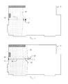
- FIG. 11 a shows a top view of an exemplary environment having spatial points 31 , the position of which can be displayed in a spatial model created according to the invention.
- these are all corner points of the interior.
- Two corner points 32 are not acquired by the spatial model, since they lie behind corners, and were therefore not imaged in the images of the image acquisition unit.
- FIG. 11 b shows as an example how such additional spatial points 32 are to be supplemented in the spatial model.
- the distance measuring device 1 is aligned so that the corresponding point 32 is imaged in an image of the image acquisition unit and—in particular triggered by a user command—a further image of a region of the interior 3 is recorded—optionally with a further distance measurement by means of a laser beam 7 to a point on a surface of the interior 3 , which is already acquired in the spatial model.
- the respective poses 95 , 96 of the image acquisition unit can thus be ascertained, and the spatial model can be supplemented with the items of information contained in the further images, including the further spatial points 32 .
- FIG. 12 shows an exemplary spatial model 30 , as is displayed on a touchscreen 28 of a handheld distance measuring device 1 according to the invention.
- the illustrated distance measuring device 1 has a hemispherical image acquisition unit 40 according to FIGS. 5 a - c , and also means for transmitting spatial model data to an external device such as a personal computer 2 by means of a wireless connection 29 .
- This can be, for example, a Bluetooth or Wi-Fi connection.
- the spatial model data can also be transmitted to a cloud in the Internet and thus distances in the environment can be ascertained on the basis of the spatial model 30 simultaneously by many users.
- the spatial model 30 which is shown as two-dimensional here for reasons of comprehensibility, can also be displayed in a three-dimensional manner in reality, of course.
- the acquired images can be laid over a grid of ascertained point coordinates.
- only the geometry without special texture can be displayed. Zooming in and out is possible in both cases, as is rotating the view.
- an existing spatial model 30 into the distance measuring device, and to perform further measurements in the corresponding space, which are automatically referenced in relation to the known spatial points by recording a further image and which supplement the spatial model 30 . Subsequent changes in the environment, for example, boreholes in a wall, can thus be incorporated in the existing spatial model 30 , possibly without having to repeat all steps of the method.
- a method for indirectly ascertaining a distance between two target points by means of a handheld distance measuring device is described hereafter as a second aspect of the invention.
- FIG. 13 shows, on the basis of a flow chart, an exemplary embodiment of a method 200 for ascertaining a distance 15 between two target points, in which a spatial relationship 98 between two target poses 91 , 92 can be ascertained by recording additional “bridging images” 73 - 75 .
- a first distance measurement is triggered and simultaneously (or essentially simultaneously) a first target image 71 is recorded on a distance measuring device according to the invention, which is aligned on a first target point.
- the distance measuring device is again aligned from another position (essentially) on the same point and a second image 71 ′ is recorded.
- the measured distance 13 is stored and a current first target pose 91 of the distance measuring device is ascertained from the target image 71 and the further image 71 ′ and optionally distances measured simultaneously with the image recordings.
- the distance measuring device is aligned by the user on the second target point. In this case, it is continuously checked in step 210 whether a further distance measurement is triggered. As long as this is not the case, it is continuously checked in step 220 whether a new pose 93 - 95 of the distance measuring device must be ascertained by recording a bridging image.
- a bridging image 73 - 75 is recorded in step 203 , which has an overlap region with the first target image or with the previous bridging image.
- a current pose 93 - 95 is ascertained on the basis of this overlap region and the previously ascertained pose of the distance measuring device.
- a distance 14 to the second target point is measured and a second target image 72 is recorded, which also has an overlap region with the previously recorded image.
- the measured distance 14 is stored, and a second target pose 92 is ascertained on the basis of the overlap region and optionally a further image 72 ′ of the region around the second target point and also optionally distances measured simultaneously with the image recordings.
- a spatial relationship 98 between the first target pose and the second target pose 92 is then derived from the ascertained poses 91 - 95 .
- the distance 15 between the first target point and the second target point can be ascertained from the spatial relationship 98 , the first distance 13 , and the second distance 14 .
- a spatial model can additionally be prepared on the basis of the images of the environment. This is achieved, for example, by a SLAM algorithm, i.e., an algorithm for simultaneously localizing the camera and mapping the environment on the basis of the camera images.
- a SLAM algorithm i.e., an algorithm for simultaneously localizing the camera and mapping the environment on the basis of the camera images.
- a spatial model is additionally calculated by means of intersection on the basis of the images of the series, for example, a point cloud which contains 3-D coordinates of points of the environment and is populated with the recorded images.
- the 3-D point cloud is preferably scaled with the aid of distances measured by the laser distance meter—a distance is preferably measured simultaneously with each image recording.
- a point cloud of the environment can be generated based on images of the environment, which were recorded using different poses, i.e., positions and alignments, of a camera.
- the point cloud can, for example, be generated by a structure from motion algorithm (SfM) or also by means of a simultaneous localization and mapping algorithm (SLAM).
- SfM structure from motion algorithm
- SLAM simultaneous localization and mapping algorithm
- a spatial model is calculated by means of photogrammetric methods based thereon and on the overlapping image regions.
- the spatial model can then be used, for example, for ascertaining the spatial relationship between the first target pose and the second target pose, and, in particular for accelerating later measurements in the same environment, can be stored on the device.
- An already existing spatial model can be supplemented or consolidated by recording further images during each measurement.
- FIGS. 14 a to 14 f Individual steps of an exemplary embodiment of a method for ascertaining a distance 15 between two target points 10 , 11 are illustrated in FIGS. 14 a to 14 f.
- FIG. 14 a shows the distance measuring device 1 in a measurement environment in a top view.
- the two target points 10 , 12 and the distance 15 to be ascertained are shown.
- the distance measuring device measures the distance 13 to the first target point 10 and records a first target image 71 simultaneously thereto. This is shown in a spatial illustration in FIG. 14 b : the target point 10 is targeted and measured by means of a laser beam 7 emitted in a first emission direction 8 .
- a relative position and alignment (first target pose 91 ) can be ascertained by means of the recorded target image 71 and the measured distance 13 .
- an additional image of the measurement region can preferably be recorded from another position and/or with another alignment, or also an existing spatial model, which is already stored in the device in particular, can be used.
- FIGS. 14 c and 14 d show the recording of a first bridging image 73 in a top view and a spatial illustration.
- the distance measuring device 1 While the user (not shown here) slowly aligns the distance measuring device 1 in the direction of the second target point 11 , the distance measuring device 1 automatically records bridging images, a first bridging image 73 here, which has an overlap region 76 with the first target image 71 . Features are then identified in the shared overlap region 76 , on the basis of which the pose 93 associated with the first bridging image 73 is ascertained by means of resection.
- a scaling distance to a point 63 of the environment imaged in the bridging image 73 is measured automatically by the distance measuring device 1 by way of a laser beam 7 emitted in a second emission direction 9 .
- This scaling distance can be used for scaling the current pose 93 of the distance measuring device 1 .
- FIG. 14 e shows the recording of further bridging images 74 , 75 and the second target image 72 in a top view. While the user furthermore continuously aligns the distance measuring device 1 on the second target point 12 , this device automatically recognizes whether further bridging images must be recorded to ascertain further poses. This can be performed, for example, via a progressive image recording by the cameras and/or an acceleration sensor of the distance measuring device 1 . If the user moves the distance measuring device 1 excessively rapidly or in a manner in which bridging images suitable for ascertaining poses cannot be recorded, the device can output a warning tone, for example. Alternatively, the recording of bridging images can also be triggered by the user, instead of automatically by the device.
- the further bridging images 74 , 75 are each recorded so that an overlap region with the respective previous image results, in which features can be identified, so that the respective pose 94 , 95 of the distance measuring device 1 can be ascertained.
- Scaling distances which are measured to points 64 , 65 of the environment imaged in the respective bridging image 74 , 75 , are measured simultaneously with the recording of the image. The scaling distances can be used for scaling the respective current pose 94 , 95 .
- the distance measuring device With triggering of the measurement to the second target point 12 by the user, the distance measuring device simultaneously records a second target image 72 , wherein again an overlap region with the last recorded bridging image 75 results, in which features can be identified, so that the second target pose 92 can be ascertained.
- FIG. 14 f illustrates the ascertainment of the distance 15 with knowledge of the two target poses 91 , 92 .
- the target poses 91 , 92 each comprise at least one relative position and orientation, for example, in relation to a reference point field of the environment or in relation to one another.
- a spatial relationship is derivable therefrom, which contains an offset 99 and an angle between the emission direction during the measurement of the first distance 13 and the emission direction during the measurement of the second distance 14 .
- the offset 99 comprises the distance between the position of the distance device, in particular the laser distance meter, during the first and the second measurements, and the direction of this distance in space.
- the distance 15 desired can thus be ascertained from the combination of the spatial relationship, the first distance 13 , and the second distance 14 .
- the images do not necessarily have to be recorded in the direction of the respective current emission direction.
- the camera can also be aligned downward or to the side, for example, to be able to ascertain the respective current pose of the distance measuring device.
- scaling by means of the laser distance meter would then not be possible.
- the images 51 - 55 also do not have to be individual images, but rather the image acquisition unit can be embodied as shown in FIG. 3 b , 3 c , 4 a - c , or 5 a - c and can have multiple cameras, wherein the images 51 - 55 are each assembled from multiple linked individual images.
- the image acquisition unit is embodied as shown in FIGS. 5 a - c , bridging images can be omitted.
- the illustrated method can also be used, in addition to the distance measurement, for the purpose of creating a spatial model of the measurement environment or of parts of the measurement environment, as was explained above with reference to FIGS. 7 a to 12 .
Landscapes
- Engineering & Computer Science (AREA)
- Physics & Mathematics (AREA)
- General Physics & Mathematics (AREA)
- Radar, Positioning & Navigation (AREA)
- Remote Sensing (AREA)
- Theoretical Computer Science (AREA)
- Electromagnetism (AREA)
- Multimedia (AREA)
- Computer Vision & Pattern Recognition (AREA)
- Computer Networks & Wireless Communication (AREA)
- Geometry (AREA)
- Optics & Photonics (AREA)
- Computer Graphics (AREA)
- Software Systems (AREA)
- Signal Processing (AREA)
- Length Measuring Devices By Optical Means (AREA)
- Measurement Of Optical Distance (AREA)
- Optical Radar Systems And Details Thereof (AREA)
Applications Claiming Priority (3)
| Application Number | Priority Date | Filing Date | Title |
|---|---|---|---|
| EP14159774.0 | 2014-03-14 | ||
| EP14159774.0A EP2918972B1 (de) | 2014-03-14 | 2014-03-14 | Verfahren und handhaltbares Entfernungsmessgerät zum Erzeugen eines Raummodells |
| EP14159774 | 2014-03-14 |
Publications (2)
| Publication Number | Publication Date |
|---|---|
| US20150309174A1 US20150309174A1 (en) | 2015-10-29 |
| US9470792B2 true US9470792B2 (en) | 2016-10-18 |
Family
ID=50280213
Family Applications (1)
| Application Number | Title | Priority Date | Filing Date |
|---|---|---|---|
| US14/645,557 Active US9470792B2 (en) | 2014-03-14 | 2015-03-12 | Method and handheld distance measuring device for creating a spatial model |
Country Status (3)
| Country | Link |
|---|---|
| US (1) | US9470792B2 (de) |
| EP (1) | EP2918972B1 (de) |
| CN (1) | CN104913763B (de) |
Cited By (7)
| Publication number | Priority date | Publication date | Assignee | Title |
|---|---|---|---|---|
| US20180060673A1 (en) * | 2016-03-31 | 2018-03-01 | International Business Machines Corporation | Object detection in crowded scenes using context-driven label propagation |
| US10140756B2 (en) | 2015-12-14 | 2018-11-27 | Leica Geosystems Ag | Method for creating a spatial model with a hand-held distance measuring device |
| US10380440B1 (en) * | 2018-10-23 | 2019-08-13 | Capital One Services, Llc | Method for determining correct scanning distance using augmented reality and machine learning models |
| US10645363B2 (en) | 2017-11-20 | 2020-05-05 | Leica Geosystems Ag | Image-based edge measurement |
| US10990202B2 (en) | 2018-10-16 | 2021-04-27 | Leica Geosystems Ag | Stylus having distance meter |
| US11494985B2 (en) | 2018-06-04 | 2022-11-08 | Timothy Coddington | System and method for mapping an interior space |
| US11509881B2 (en) | 2017-11-20 | 2022-11-22 | Leica Geosystems Ag | Stereo camera and stereophotogrammetric method |
Families Citing this family (32)
| Publication number | Priority date | Publication date | Assignee | Title |
|---|---|---|---|---|
| JP6505234B2 (ja) | 2015-08-31 | 2019-04-24 | 富士フイルム株式会社 | 測距装置、測距用導出方法、及び測距用導出プログラム |
| JP6677474B2 (ja) * | 2015-09-29 | 2020-04-08 | 日立オートモティブシステムズ株式会社 | 周辺認識装置 |
| CN106767584B (zh) * | 2015-11-20 | 2019-12-06 | 富泰华工业(深圳)有限公司 | 物体表面点三维坐标测量装置及测量方法 |
| EP3182065A1 (de) * | 2015-12-14 | 2017-06-21 | Leica Geosystems AG | Handhaltbares entfernungsmessgerät und verfahren zum erfassen relativer positionen |
| US10211660B2 (en) | 2016-02-08 | 2019-02-19 | Cree, Inc. | LED lighting device with adaptive profiles for controlling power consumption |
| US11567201B2 (en) | 2016-03-11 | 2023-01-31 | Kaarta, Inc. | Laser scanner with real-time, online ego-motion estimation |
| US11573325B2 (en) | 2016-03-11 | 2023-02-07 | Kaarta, Inc. | Systems and methods for improvements in scanning and mapping |
| US10989542B2 (en) | 2016-03-11 | 2021-04-27 | Kaarta, Inc. | Aligning measured signal data with slam localization data and uses thereof |
| WO2017155970A1 (en) | 2016-03-11 | 2017-09-14 | Kaarta, Inc. | Laser scanner with real-time, online ego-motion estimation |
| DE102016211742A1 (de) * | 2016-06-29 | 2018-01-04 | Robert Bosch Gmbh | Verfahren zum Betrieb eines Laserentfernungsmessgeräts |
| CN110062893A (zh) * | 2016-10-07 | 2019-07-26 | Cmte发展有限公司 | 用于对象形状和姿态的点云诊断检验的系统和方法 |
| EP3333538B1 (de) * | 2016-12-07 | 2020-09-09 | Hexagon Technology Center GmbH | Vis-scanner |
| DE102016225275A1 (de) * | 2016-12-16 | 2018-06-21 | Robert Bosch Gmbh | Verfahren zum Betrieb eines Laserentfernungsmessgeräts |
| US10451229B2 (en) | 2017-01-30 | 2019-10-22 | Ideal Industries Lighting Llc | Skylight fixture |
| US10465869B2 (en) | 2017-01-30 | 2019-11-05 | Ideal Industries Lighting Llc | Skylight fixture |
| CN107064950A (zh) * | 2017-02-24 | 2017-08-18 | 上海诺司纬光电仪器有限公司 | 激光定位装置及激光定位方法 |
| EP3416027B1 (de) | 2017-06-12 | 2020-04-08 | Hexagon Technology Center GmbH | Augmentierte realität vorrichtung und system mit nahtloser überbrückung |
| US9894740B1 (en) | 2017-06-13 | 2018-02-13 | Cree, Inc. | Intelligent lighting module for a lighting fixture |
| EP3688410B1 (de) * | 2017-09-26 | 2021-12-29 | Trimble AB | Warteschlange von datensammelaufgaben für vermessungsinstrument |
| WO2019099605A1 (en) | 2017-11-17 | 2019-05-23 | Kaarta, Inc. | Methods and systems for geo-referencing mapping systems |
| CA3086254A1 (en) * | 2017-12-29 | 2019-07-04 | Aposys Technologies Inc. | A laser-based device for mapping a computed geometry relative to a reference geometry |
| US10830400B2 (en) | 2018-02-08 | 2020-11-10 | Ideal Industries Lighting Llc | Environmental simulation for indoor spaces |
| WO2019165194A1 (en) | 2018-02-23 | 2019-08-29 | Kaarta, Inc. | Methods and systems for processing and colorizing point clouds and meshes |
| US10991215B2 (en) | 2018-03-20 | 2021-04-27 | Ideal Industries Lighting Llc | Intelligent signage |
| WO2019195270A1 (en) | 2018-04-03 | 2019-10-10 | Kaarta, Inc. | Methods and systems for real or near real-time point cloud map data confidence evaluation |
| WO2020009826A1 (en) | 2018-07-05 | 2020-01-09 | Kaarta, Inc. | Methods and systems for auto-leveling of point clouds and 3d models |
| DE102018125397A1 (de) * | 2018-10-15 | 2020-04-16 | Visualix GmbH | Verfahren und Vorrichtung zur Bestimmung einer Umgebungskarte |
| CN113597534B (zh) * | 2019-03-26 | 2023-07-25 | 松下知识产权经营株式会社 | 测距成像系统、测距成像方法和程序 |
| CN110375717A (zh) * | 2019-08-02 | 2019-10-25 | 桂林理工大学 | 一种实时面积量算的近景摄影测量方法 |
| US12130154B2 (en) * | 2019-10-02 | 2024-10-29 | Top Measure Instrument Company | Automatic electronic rangefinder |
| WO2021086943A1 (en) | 2019-10-28 | 2021-05-06 | Ideal Industries Lighting Llc | Systems and methods for providing dynamic lighting |
| US20240011772A1 (en) * | 2022-07-06 | 2024-01-11 | Robbox Inc. | Digital measuring and detection apparatus with interactive screen |
Citations (12)
| Publication number | Priority date | Publication date | Assignee | Title |
|---|---|---|---|---|
| EP0738899A1 (de) | 1993-05-15 | 1996-10-23 | Leica AG | Vorrichtung zur Distanzmessung |
| WO2002050564A2 (de) | 2000-12-21 | 2002-06-27 | Leica Geosystems Ag | Vorrichtung zur entfernungsmessung, sowie entfernungsmesser und anschlagelement dafür |
| EP1517117A1 (de) | 2003-09-22 | 2005-03-23 | Leica Geosystems AG | Verfahren und System zur Bestimmung einer Aktualposition eines Positionierungsgerätes |
| DE102006054324A1 (de) | 2006-11-17 | 2008-05-21 | Robert Bosch Gmbh | Verfahren zur bildbasierten Vermessung |
| DE102008054453A1 (de) | 2008-12-10 | 2010-06-17 | Robert Bosch Gmbh | Messsystem zur Vermessung von Räumen und/oder von Objekten |
| US20100246892A1 (en) | 2007-07-23 | 2010-09-30 | Panasonic Corporation | Compound eye type imaging apparatus with distance measuring capability |
| DE102010038507A1 (de) | 2010-07-28 | 2012-02-02 | Robert Bosch Gmbh | Parallele Online-Offline Rekonstruktion für drei-dimensionale Raumvermessung |
| DE102010042733A1 (de) | 2010-10-21 | 2012-04-26 | Robert Bosch Gmbh | Erfassung und Darstellung texturierter drei-dimensionaler Geometrien |
| US20130228620A1 (en) | 2012-03-01 | 2013-09-05 | Trimble Navigation Limited | Method and system for rfid-assisted imaging |
| US20130314688A1 (en) | 2012-05-27 | 2013-11-28 | Alexander Likholyot | Indoor surveying apparatus |
| EP2669707A1 (de) | 2012-05-29 | 2013-12-04 | Leica Geosystems AG | Verfahren und handhaltbares Entfernungsmessgerät zur indirekten Entfernungsmessung mittels bildgestützter Winkelbestimmungsfunktion |
| EP2698602A1 (de) | 2012-08-16 | 2014-02-19 | Leica Geosystems AG | Handhaltbares Entfernungsmessgerät mit Winkelbestimmungseinheit |
Family Cites Families (4)
| Publication number | Priority date | Publication date | Assignee | Title |
|---|---|---|---|---|
| AU2004275018A1 (en) * | 2003-09-12 | 2005-03-31 | Leica Geosystems Ag | Method and device for ensuring interaction between a distance meter and a surveying application |
| DE102004023998A1 (de) * | 2004-05-14 | 2005-12-08 | Robert Bosch Gmbh | Vorrichtung zur optischen Distanzmessung |
| CN2906644Y (zh) * | 2006-06-07 | 2007-05-30 | 北京石油化工学院 | 大视场激光回波探测光学装置 |
| CN102735182A (zh) * | 2011-04-15 | 2012-10-17 | 顾建达 | 利用手持测距器扫描建筑物内轮廓的方法及其设备 |
-
2014
- 2014-03-14 EP EP14159774.0A patent/EP2918972B1/de active Active
-
2015
- 2015-03-12 US US14/645,557 patent/US9470792B2/en active Active
- 2015-03-16 CN CN201510113983.4A patent/CN104913763B/zh active Active
Patent Citations (15)
| Publication number | Priority date | Publication date | Assignee | Title |
|---|---|---|---|---|
| EP0701702B1 (de) | 1993-05-15 | 1997-02-05 | Leica AG | Vorrichtung zur distanzmessung |
| EP0738899A1 (de) | 1993-05-15 | 1996-10-23 | Leica AG | Vorrichtung zur Distanzmessung |
| WO2002050564A2 (de) | 2000-12-21 | 2002-06-27 | Leica Geosystems Ag | Vorrichtung zur entfernungsmessung, sowie entfernungsmesser und anschlagelement dafür |
| EP1517117A1 (de) | 2003-09-22 | 2005-03-23 | Leica Geosystems AG | Verfahren und System zur Bestimmung einer Aktualposition eines Positionierungsgerätes |
| US20070064246A1 (en) * | 2003-09-22 | 2007-03-22 | Bernhard Braunecker | Method and system for determining the spatial position of a hand-held measuring appliance |
| DE102006054324A1 (de) | 2006-11-17 | 2008-05-21 | Robert Bosch Gmbh | Verfahren zur bildbasierten Vermessung |
| US20100246892A1 (en) | 2007-07-23 | 2010-09-30 | Panasonic Corporation | Compound eye type imaging apparatus with distance measuring capability |
| DE102008054453A1 (de) | 2008-12-10 | 2010-06-17 | Robert Bosch Gmbh | Messsystem zur Vermessung von Räumen und/oder von Objekten |
| DE102010038507A1 (de) | 2010-07-28 | 2012-02-02 | Robert Bosch Gmbh | Parallele Online-Offline Rekonstruktion für drei-dimensionale Raumvermessung |
| US20130222544A1 (en) * | 2010-07-28 | 2013-08-29 | Robert Bosch Gmbh | Parallel Online-Offline Reconstruction for Three-Dimensional Space Measurement |
| DE102010042733A1 (de) | 2010-10-21 | 2012-04-26 | Robert Bosch Gmbh | Erfassung und Darstellung texturierter drei-dimensionaler Geometrien |
| US20130228620A1 (en) | 2012-03-01 | 2013-09-05 | Trimble Navigation Limited | Method and system for rfid-assisted imaging |
| US20130314688A1 (en) | 2012-05-27 | 2013-11-28 | Alexander Likholyot | Indoor surveying apparatus |
| EP2669707A1 (de) | 2012-05-29 | 2013-12-04 | Leica Geosystems AG | Verfahren und handhaltbares Entfernungsmessgerät zur indirekten Entfernungsmessung mittels bildgestützter Winkelbestimmungsfunktion |
| EP2698602A1 (de) | 2012-08-16 | 2014-02-19 | Leica Geosystems AG | Handhaltbares Entfernungsmessgerät mit Winkelbestimmungseinheit |
Non-Patent Citations (3)
| Title |
|---|
| CADGorilla: "AutoCAD Tutorial-Measuring Tools", Oct. 20, 2010, Retrieved from the Internet (YouTube), (provided by the Applicant). * |
| European Search Report dated Aug. 12, 2015 as received in Application No. 14159774. |
| The CADGorilla: "AutoCAD Tutorial-Measuring Tools", Accessed at https://www.youtube.com/watch?v=YcfnSj0-ke4, Dated Sep. 20, 2010, pp. 2. |
Cited By (14)
| Publication number | Priority date | Publication date | Assignee | Title |
|---|---|---|---|---|
| US10140756B2 (en) | 2015-12-14 | 2018-11-27 | Leica Geosystems Ag | Method for creating a spatial model with a hand-held distance measuring device |
| US9971942B2 (en) * | 2016-03-31 | 2018-05-15 | International Business Machines Corporation | Object detection in crowded scenes using context-driven label propagation |
| US20180060673A1 (en) * | 2016-03-31 | 2018-03-01 | International Business Machines Corporation | Object detection in crowded scenes using context-driven label propagation |
| US11509881B2 (en) | 2017-11-20 | 2022-11-22 | Leica Geosystems Ag | Stereo camera and stereophotogrammetric method |
| US10645363B2 (en) | 2017-11-20 | 2020-05-05 | Leica Geosystems Ag | Image-based edge measurement |
| US11494985B2 (en) | 2018-06-04 | 2022-11-08 | Timothy Coddington | System and method for mapping an interior space |
| US10990202B2 (en) | 2018-10-16 | 2021-04-27 | Leica Geosystems Ag | Stylus having distance meter |
| US10380440B1 (en) * | 2018-10-23 | 2019-08-13 | Capital One Services, Llc | Method for determining correct scanning distance using augmented reality and machine learning models |
| US11275958B2 (en) | 2018-10-23 | 2022-03-15 | Capital One Services, Llc | Method for determining correct scanning distance using augmented reality and machine learning models |
| US10671867B2 (en) | 2018-10-23 | 2020-06-02 | Capital One Services, Llc | Method for determining correct scanning distance using augmented reality and machine learning models |
| US10521681B1 (en) | 2018-10-23 | 2019-12-31 | Capital One Services, Llc | Method for determining correct scanning distance using augmented reality and machine learning models |
| US11594045B2 (en) | 2018-10-23 | 2023-02-28 | Capital One Services, Llc | Method for determining correct scanning distance using augmented reality and machine learning models |
| US12008724B2 (en) | 2018-10-23 | 2024-06-11 | Capital One Services, Llc | Method for determining correct scanning distance using augmented reality and machine learning models |
| US12444147B2 (en) | 2018-10-23 | 2025-10-14 | Capital One Services, Llc | Method for determining correct scanning distance using augmented reality and machine learning models |
Also Published As
| Publication number | Publication date |
|---|---|
| EP2918972A3 (de) | 2015-09-23 |
| EP2918972A2 (de) | 2015-09-16 |
| CN104913763A (zh) | 2015-09-16 |
| CN104913763B (zh) | 2017-10-13 |
| EP2918972B1 (de) | 2019-10-09 |
| US20150309174A1 (en) | 2015-10-29 |
Similar Documents
| Publication | Publication Date | Title |
|---|---|---|
| US20150309174A1 (en) | Method and handheld distance measuring device for creating a spatial model | |
| US10140756B2 (en) | Method for creating a spatial model with a hand-held distance measuring device | |
| CN107402000B (zh) | 用于将显示装置相对于测量仪器相互关联的方法和系统 | |
| US8699005B2 (en) | Indoor surveying apparatus | |
| US10187567B2 (en) | Method and handheld distance measurement device for indirect distance measurement by means of image-assisted angle determination function | |
| US9646384B2 (en) | 3D feature descriptors with camera pose information | |
| US9247239B2 (en) | Use of overlap areas to optimize bundle adjustment | |
| US8510039B1 (en) | Methods and apparatus for three-dimensional localization and mapping | |
| US20210374978A1 (en) | Capturing environmental scans using anchor objects for registration | |
| US20120105825A1 (en) | Measuring device for noncontact measurement of distances to a target object | |
| TW201337306A (zh) | 用於建築工地之資訊擷取 | |
| JP2025120451A (ja) | 入力装置および入力装置の入力方法、ならびに、出力装置および出力装置の出力方法 | |
| US12008783B2 (en) | Reality capture device | |
| JP6806154B2 (ja) | ガス計測システム及びガス計測プログラム | |
| Ye et al. | 6-DOF pose estimation of a robotic navigation aid by tracking visual and geometric features | |
| EP4258023A1 (de) | Erfassung einer dreidimensionalen darstellung einer umgebung mit einer mobilen vorrichtung | |
| KR20130002834A (ko) | 자율 이동 방법 및 그 장치 | |
| US12154229B2 (en) | Bar arrangement inspection result display system | |
| US10447991B1 (en) | System and method of mapping elements inside walls | |
| US11009887B2 (en) | Systems and methods for remote visual inspection of a closed space | |
| Pal et al. | 3D point cloud generation from 2D depth camera images using successive triangulation | |
| US20240069203A1 (en) | Global optimization methods for mobile coordinate scanners | |
| US20240210563A1 (en) | Scanning project planning | |
| Li et al. | A combined vision-inertial fusion approach for 6-DoF object pose estimation | |
| KR20230130024A (ko) | 카메라의 상태를 결정하기 위한 방법 및 시스템 |
Legal Events
| Date | Code | Title | Description |
|---|---|---|---|
| AS | Assignment |
Owner name: LEICA GEOSYSTEMS AG, SWITZERLAND Free format text: ASSIGNMENT OF ASSIGNORS INTEREST;ASSIGNOR:GIGER, KURT;REEL/FRAME:035154/0684 Effective date: 20150205 |
|
| STCF | Information on status: patent grant |
Free format text: PATENTED CASE |
|
| FEPP | Fee payment procedure |
Free format text: PAYOR NUMBER ASSIGNED (ORIGINAL EVENT CODE: ASPN); ENTITY STATUS OF PATENT OWNER: LARGE ENTITY |
|
| MAFP | Maintenance fee payment |
Free format text: PAYMENT OF MAINTENANCE FEE, 4TH YEAR, LARGE ENTITY (ORIGINAL EVENT CODE: M1551); ENTITY STATUS OF PATENT OWNER: LARGE ENTITY Year of fee payment: 4 |
|
| MAFP | Maintenance fee payment |
Free format text: PAYMENT OF MAINTENANCE FEE, 8TH YEAR, LARGE ENTITY (ORIGINAL EVENT CODE: M1552); ENTITY STATUS OF PATENT OWNER: LARGE ENTITY Year of fee payment: 8 |