US9470262B2 - Bearing arrangement and method - Google Patents
Bearing arrangement and method Download PDFInfo
- Publication number
- US9470262B2 US9470262B2 US14/631,245 US201514631245A US9470262B2 US 9470262 B2 US9470262 B2 US 9470262B2 US 201514631245 A US201514631245 A US 201514631245A US 9470262 B2 US9470262 B2 US 9470262B2
- Authority
- US
- United States
- Prior art keywords
- thrust bearing
- bearing
- thrust
- resilient elements
- load
- Prior art date
- Legal status (The legal status is an assumption and is not a legal conclusion. Google has not performed a legal analysis and makes no representation as to the accuracy of the status listed.)
- Active
Links
- 238000000034 method Methods 0.000 title description 6
- 238000006073 displacement reaction Methods 0.000 claims description 44
- 238000005259 measurement Methods 0.000 claims description 16
- 125000006850 spacer group Chemical group 0.000 claims description 14
- 230000004323 axial length Effects 0.000 claims description 6
- 238000005096 rolling process Methods 0.000 description 30
- 238000012360 testing method Methods 0.000 description 10
- 229910000831 Steel Inorganic materials 0.000 description 8
- 239000010959 steel Substances 0.000 description 8
- 238000004519 manufacturing process Methods 0.000 description 6
- 238000013461 design Methods 0.000 description 5
- 230000000694 effects Effects 0.000 description 5
- 239000000463 material Substances 0.000 description 4
- 238000005452 bending Methods 0.000 description 3
- 239000000523 sample Substances 0.000 description 3
- 239000010935 stainless steel Substances 0.000 description 3
- 229910001220 stainless steel Inorganic materials 0.000 description 3
- 229910045601 alloy Inorganic materials 0.000 description 2
- 239000000956 alloy Substances 0.000 description 2
- 238000011088 calibration curve Methods 0.000 description 2
- 239000013013 elastic material Substances 0.000 description 2
- 230000002706 hydrostatic effect Effects 0.000 description 2
- 238000009434 installation Methods 0.000 description 2
- 238000012423 maintenance Methods 0.000 description 2
- 230000007935 neutral effect Effects 0.000 description 2
- 230000003287 optical effect Effects 0.000 description 2
- 238000000926 separation method Methods 0.000 description 2
- 229910000851 Alloy steel Inorganic materials 0.000 description 1
- 229910001209 Low-carbon steel Inorganic materials 0.000 description 1
- 229910000990 Ni alloy Inorganic materials 0.000 description 1
- 229910001069 Ti alloy Inorganic materials 0.000 description 1
- RTAQQCXQSZGOHL-UHFFFAOYSA-N Titanium Chemical compound [Ti] RTAQQCXQSZGOHL-UHFFFAOYSA-N 0.000 description 1
- 230000002411 adverse Effects 0.000 description 1
- 239000000969 carrier Substances 0.000 description 1
- 239000000919 ceramic Substances 0.000 description 1
- 238000010276 construction Methods 0.000 description 1
- 239000004035 construction material Substances 0.000 description 1
- 239000013078 crystal Substances 0.000 description 1
- 238000001514 detection method Methods 0.000 description 1
- 238000005553 drilling Methods 0.000 description 1
- 230000005489 elastic deformation Effects 0.000 description 1
- 230000007613 environmental effect Effects 0.000 description 1
- 239000012530 fluid Substances 0.000 description 1
- 238000010438 heat treatment Methods 0.000 description 1
- 238000011065 in-situ storage Methods 0.000 description 1
- 229910000734 martensite Inorganic materials 0.000 description 1
- 230000002035 prolonged effect Effects 0.000 description 1
- 230000002441 reversible effect Effects 0.000 description 1
- 230000003068 static effect Effects 0.000 description 1
- 230000009885 systemic effect Effects 0.000 description 1
- 239000010936 titanium Substances 0.000 description 1
- 229910052719 titanium Inorganic materials 0.000 description 1
- 230000009466 transformation Effects 0.000 description 1
Images


Classifications
-
- F—MECHANICAL ENGINEERING; LIGHTING; HEATING; WEAPONS; BLASTING
- F16—ENGINEERING ELEMENTS AND UNITS; GENERAL MEASURES FOR PRODUCING AND MAINTAINING EFFECTIVE FUNCTIONING OF MACHINES OR INSTALLATIONS; THERMAL INSULATION IN GENERAL
- F16C—SHAFTS; FLEXIBLE SHAFTS; ELEMENTS OR CRANKSHAFT MECHANISMS; ROTARY BODIES OTHER THAN GEARING ELEMENTS; BEARINGS
- F16C25/00—Bearings for exclusively rotary movement adjustable for wear or play
- F16C25/06—Ball or roller bearings
- F16C25/08—Ball or roller bearings self-adjusting
- F16C25/083—Ball or roller bearings self-adjusting with resilient means acting axially on a race ring to preload the bearing
-
- F—MECHANICAL ENGINEERING; LIGHTING; HEATING; WEAPONS; BLASTING
- F01—MACHINES OR ENGINES IN GENERAL; ENGINE PLANTS IN GENERAL; STEAM ENGINES
- F01D—NON-POSITIVE DISPLACEMENT MACHINES OR ENGINES, e.g. STEAM TURBINES
- F01D25/00—Component parts, details, or accessories, not provided for in, or of interest apart from, other groups
- F01D25/16—Arrangement of bearings; Supporting or mounting bearings in casings
- F01D25/162—Bearing supports
-
- F—MECHANICAL ENGINEERING; LIGHTING; HEATING; WEAPONS; BLASTING
- F16—ENGINEERING ELEMENTS AND UNITS; GENERAL MEASURES FOR PRODUCING AND MAINTAINING EFFECTIVE FUNCTIONING OF MACHINES OR INSTALLATIONS; THERMAL INSULATION IN GENERAL
- F16C—SHAFTS; FLEXIBLE SHAFTS; ELEMENTS OR CRANKSHAFT MECHANISMS; ROTARY BODIES OTHER THAN GEARING ELEMENTS; BEARINGS
- F16C19/00—Bearings with rolling contact, for exclusively rotary movement
- F16C19/54—Systems consisting of a plurality of bearings with rolling friction
- F16C19/541—Systems consisting of juxtaposed rolling bearings including at least one angular contact bearing
- F16C19/542—Systems consisting of juxtaposed rolling bearings including at least one angular contact bearing with two rolling bearings with angular contact
-
- F—MECHANICAL ENGINEERING; LIGHTING; HEATING; WEAPONS; BLASTING
- F16—ENGINEERING ELEMENTS AND UNITS; GENERAL MEASURES FOR PRODUCING AND MAINTAINING EFFECTIVE FUNCTIONING OF MACHINES OR INSTALLATIONS; THERMAL INSULATION IN GENERAL
- F16C—SHAFTS; FLEXIBLE SHAFTS; ELEMENTS OR CRANKSHAFT MECHANISMS; ROTARY BODIES OTHER THAN GEARING ELEMENTS; BEARINGS
- F16C33/00—Parts of bearings; Special methods for making bearings or parts thereof
- F16C33/30—Parts of ball or roller bearings
- F16C33/58—Raceways; Race rings
- F16C33/583—Details of specific parts of races
- F16C33/586—Details of specific parts of races outside the space between the races, e.g. end faces or bore of inner ring
-
- F—MECHANICAL ENGINEERING; LIGHTING; HEATING; WEAPONS; BLASTING
- F16—ENGINEERING ELEMENTS AND UNITS; GENERAL MEASURES FOR PRODUCING AND MAINTAINING EFFECTIVE FUNCTIONING OF MACHINES OR INSTALLATIONS; THERMAL INSULATION IN GENERAL
- F16C—SHAFTS; FLEXIBLE SHAFTS; ELEMENTS OR CRANKSHAFT MECHANISMS; ROTARY BODIES OTHER THAN GEARING ELEMENTS; BEARINGS
- F16C41/00—Other accessories, e.g. devices integrated in the bearing not relating to the bearing function as such
- F16C41/02—Arrangements for equalising the load on a plurality of bearings or their elements
-
- G—PHYSICS
- G01—MEASURING; TESTING
- G01M—TESTING STATIC OR DYNAMIC BALANCE OF MACHINES OR STRUCTURES; TESTING OF STRUCTURES OR APPARATUS, NOT OTHERWISE PROVIDED FOR
- G01M13/00—Testing of machine parts
- G01M13/04—Bearings
-
- F—MECHANICAL ENGINEERING; LIGHTING; HEATING; WEAPONS; BLASTING
- F05—INDEXING SCHEMES RELATING TO ENGINES OR PUMPS IN VARIOUS SUBCLASSES OF CLASSES F01-F04
- F05D—INDEXING SCHEME FOR ASPECTS RELATING TO NON-POSITIVE-DISPLACEMENT MACHINES OR ENGINES, GAS-TURBINES OR JET-PROPULSION PLANTS
- F05D2240/00—Components
- F05D2240/50—Bearings
- F05D2240/52—Axial thrust bearings
-
- F—MECHANICAL ENGINEERING; LIGHTING; HEATING; WEAPONS; BLASTING
- F05—INDEXING SCHEMES RELATING TO ENGINES OR PUMPS IN VARIOUS SUBCLASSES OF CLASSES F01-F04
- F05D—INDEXING SCHEME FOR ASPECTS RELATING TO NON-POSITIVE-DISPLACEMENT MACHINES OR ENGINES, GAS-TURBINES OR JET-PROPULSION PLANTS
- F05D2260/00—Function
- F05D2260/83—Testing, e.g. methods, components or tools therefor
-
- F—MECHANICAL ENGINEERING; LIGHTING; HEATING; WEAPONS; BLASTING
- F05—INDEXING SCHEMES RELATING TO ENGINES OR PUMPS IN VARIOUS SUBCLASSES OF CLASSES F01-F04
- F05D—INDEXING SCHEME FOR ASPECTS RELATING TO NON-POSITIVE-DISPLACEMENT MACHINES OR ENGINES, GAS-TURBINES OR JET-PROPULSION PLANTS
- F05D2300/00—Materials; Properties thereof
- F05D2300/50—Intrinsic material properties or characteristics
- F05D2300/501—Elasticity
-
- F—MECHANICAL ENGINEERING; LIGHTING; HEATING; WEAPONS; BLASTING
- F16—ENGINEERING ELEMENTS AND UNITS; GENERAL MEASURES FOR PRODUCING AND MAINTAINING EFFECTIVE FUNCTIONING OF MACHINES OR INSTALLATIONS; THERMAL INSULATION IN GENERAL
- F16C—SHAFTS; FLEXIBLE SHAFTS; ELEMENTS OR CRANKSHAFT MECHANISMS; ROTARY BODIES OTHER THAN GEARING ELEMENTS; BEARINGS
- F16C19/00—Bearings with rolling contact, for exclusively rotary movement
- F16C19/02—Bearings with rolling contact, for exclusively rotary movement with bearing balls essentially of the same size in one or more circular rows
- F16C19/14—Bearings with rolling contact, for exclusively rotary movement with bearing balls essentially of the same size in one or more circular rows for both radial and axial load
- F16C19/16—Bearings with rolling contact, for exclusively rotary movement with bearing balls essentially of the same size in one or more circular rows for both radial and axial load with a single row of balls
-
- F—MECHANICAL ENGINEERING; LIGHTING; HEATING; WEAPONS; BLASTING
- F16—ENGINEERING ELEMENTS AND UNITS; GENERAL MEASURES FOR PRODUCING AND MAINTAINING EFFECTIVE FUNCTIONING OF MACHINES OR INSTALLATIONS; THERMAL INSULATION IN GENERAL
- F16C—SHAFTS; FLEXIBLE SHAFTS; ELEMENTS OR CRANKSHAFT MECHANISMS; ROTARY BODIES OTHER THAN GEARING ELEMENTS; BEARINGS
- F16C19/00—Bearings with rolling contact, for exclusively rotary movement
- F16C19/52—Bearings with rolling contact, for exclusively rotary movement with devices affected by abnormal or undesired conditions
- F16C19/522—Bearings with rolling contact, for exclusively rotary movement with devices affected by abnormal or undesired conditions related to load on the bearing, e.g. bearings with load sensors or means to protect the bearing against overload
-
- F—MECHANICAL ENGINEERING; LIGHTING; HEATING; WEAPONS; BLASTING
- F16—ENGINEERING ELEMENTS AND UNITS; GENERAL MEASURES FOR PRODUCING AND MAINTAINING EFFECTIVE FUNCTIONING OF MACHINES OR INSTALLATIONS; THERMAL INSULATION IN GENERAL
- F16C—SHAFTS; FLEXIBLE SHAFTS; ELEMENTS OR CRANKSHAFT MECHANISMS; ROTARY BODIES OTHER THAN GEARING ELEMENTS; BEARINGS
- F16C19/00—Bearings with rolling contact, for exclusively rotary movement
- F16C19/54—Systems consisting of a plurality of bearings with rolling friction
-
- F—MECHANICAL ENGINEERING; LIGHTING; HEATING; WEAPONS; BLASTING
- F16—ENGINEERING ELEMENTS AND UNITS; GENERAL MEASURES FOR PRODUCING AND MAINTAINING EFFECTIVE FUNCTIONING OF MACHINES OR INSTALLATIONS; THERMAL INSULATION IN GENERAL
- F16C—SHAFTS; FLEXIBLE SHAFTS; ELEMENTS OR CRANKSHAFT MECHANISMS; ROTARY BODIES OTHER THAN GEARING ELEMENTS; BEARINGS
- F16C2233/00—Monitoring condition, e.g. temperature, load, vibration
-
- F—MECHANICAL ENGINEERING; LIGHTING; HEATING; WEAPONS; BLASTING
- F16—ENGINEERING ELEMENTS AND UNITS; GENERAL MEASURES FOR PRODUCING AND MAINTAINING EFFECTIVE FUNCTIONING OF MACHINES OR INSTALLATIONS; THERMAL INSULATION IN GENERAL
- F16C—SHAFTS; FLEXIBLE SHAFTS; ELEMENTS OR CRANKSHAFT MECHANISMS; ROTARY BODIES OTHER THAN GEARING ELEMENTS; BEARINGS
- F16C2237/00—Repair or replacement
-
- F—MECHANICAL ENGINEERING; LIGHTING; HEATING; WEAPONS; BLASTING
- F16—ENGINEERING ELEMENTS AND UNITS; GENERAL MEASURES FOR PRODUCING AND MAINTAINING EFFECTIVE FUNCTIONING OF MACHINES OR INSTALLATIONS; THERMAL INSULATION IN GENERAL
- F16C—SHAFTS; FLEXIBLE SHAFTS; ELEMENTS OR CRANKSHAFT MECHANISMS; ROTARY BODIES OTHER THAN GEARING ELEMENTS; BEARINGS
- F16C2360/00—Engines or pumps
- F16C2360/23—Gas turbine engines
-
- F—MECHANICAL ENGINEERING; LIGHTING; HEATING; WEAPONS; BLASTING
- F16—ENGINEERING ELEMENTS AND UNITS; GENERAL MEASURES FOR PRODUCING AND MAINTAINING EFFECTIVE FUNCTIONING OF MACHINES OR INSTALLATIONS; THERMAL INSULATION IN GENERAL
- F16C—SHAFTS; FLEXIBLE SHAFTS; ELEMENTS OR CRANKSHAFT MECHANISMS; ROTARY BODIES OTHER THAN GEARING ELEMENTS; BEARINGS
- F16C27/00—Elastic or yielding bearings or bearing supports, for exclusively rotary movement
- F16C27/08—Elastic or yielding bearings or bearing supports, for exclusively rotary movement primarily for axial load, e.g. for vertically-arranged shafts
-
- Y—GENERAL TAGGING OF NEW TECHNOLOGICAL DEVELOPMENTS; GENERAL TAGGING OF CROSS-SECTIONAL TECHNOLOGIES SPANNING OVER SEVERAL SECTIONS OF THE IPC; TECHNICAL SUBJECTS COVERED BY FORMER USPC CROSS-REFERENCE ART COLLECTIONS [XRACs] AND DIGESTS
- Y02—TECHNOLOGIES OR APPLICATIONS FOR MITIGATION OR ADAPTATION AGAINST CLIMATE CHANGE
- Y02T—CLIMATE CHANGE MITIGATION TECHNOLOGIES RELATED TO TRANSPORTATION
- Y02T50/00—Aeronautics or air transport
- Y02T50/60—Efficient propulsion technologies, e.g. for aircraft
-
- Y02T50/671—
Definitions
- the present invention relates to a bearing arrangement, in particular a load sharing bearing arrangement and the determination of loads thereon.
- Rotating shafts such as those used in gas turbine engines, typically require bearings to support relatively moving or rotating components. Where light weight and minimum power loss from friction are required, rolling element bearings are common and may be used to react both radial and thrust loads.
- the materials of the rolling elements and/or bearing races may expand in use due to heating, which can exacerbate further the geometrical variations and lead to a “runaway” effect in which one bearing takes progressively more of the load, potentially resulting in bearing failure. This may occur even if matched bearings are selected and installed because even very small geometrical variations between the bearings may be magnified under the severe environmental operating conditions in gas turbine engines.
- a bearing arrangement comprising: first and second thrust bearings, each including an inner race which is disposed on a shaft and an outer race which is supported by at least one resilient element; wherein applying a shaft thrust load elastically deforms the resilient elements so as to axially displace the respective outer races in order that the thrust load is shared between the first and second thrust bearings.
- the supporting resilient elements enable the axial thrust load to be shared between the first and second thrust bearings, such that geometrical variations and/or differential expansions between the thrust bearings may be tolerated. Hence, the requirement for careful control and matching of bearings is eliminated, or at least relaxed.
- the resilient elements may be elastically deformed such that the thrust load is substantially equally shared between the first and second thrust bearings.
- each of the first and second thrust bearings may be supported by two resilient elements.
- the outer race of each of the first and second thrust bearings may be supported by four resilient elements.
- the four resilient elements may be arranged in pairs.
- Each of the resilient elements may extend substantially perpendicularly to the axial direction, when in an undeformed condition. Or, each of the resilient elements may be inclined relative to an imaginary line which extends perpendicularly to the axial direction, when in an undeformed condition.
- Each of the resilient elements may be within the projected axial length of the respective thrust bearing, when in an undeformed condition. Each of the resilient elements may extend beyond the projected axial length of the respective thrust bearing, when in the elastically deformed condition.
- the resilient elements may comprise diaphragms.
- the resilient elements may comprise beams or radially-extending fingers.
- the diaphragms, or the beams or radially-extending fingers may be generally flat, or curved.
- the bearing arrangement may comprise three or more thrust bearings.
- the bearings may be axially spaced on the shaft.
- a spacer element may be disposed between the inner races to define the axial distance between the thrust bearings.
- the thrust bearings may be ball bearings, tapered cylindrical roller bearings, hydrostatic bearings, or hydrodynamic bearings.
- the outer races may be supported by the respective resilient elements on a bearing housing of a gas turbine engine.
- a gas turbine engine comprising a bearing arrangement as described herein above.
- a bearing arrangement comprising: first and second thrust bearings, each including an inner race on a shaft and an outer race which is supported by at least one resilient element; wherein applying a shaft thrust load axially displaces the outer races against resistance from the respective resilient elements so that the thrust load is shared between the first and second thrust bearings.
- a method of determining the axial load on load-sharing thrust bearings comprising the steps of: providing first and second thrust bearings, each including an inner race and an outer race which is supported by at least one resilient element; applying a test axial load to each of the first and second thrust bearings, to elastically deform the at least one resilient element so as to axially displace the outer race; determining the test axial displacement of each outer race in order to obtain calibration data comprising values of axial load versus axial displacement; applying an in-service axial load to the first and second thrust bearings to elastically deform the resilient elements so as to axially displace the respective outer races; measuring the in-service axial displacement of each outer race; and based on the measured in-service axial displacements, inferring from the calibration data the values of the in-service axial loads on the first and second thrust bearings.
- Calibrating the thrust bearings, prior to in-service operation enables determination of the individual operating loads on the bearings. This knowledge of the in-service loads can be useful for predicting maintenance schedules and diagnosing problems.
- the step of applying a test axial load to each of the first and second thrust bearings, to elastically deform the at least one resilient element so as to axially displace the outer race may be preceded by a step of: applying a relatively smaller test axial load, in order to axially displace the inner race to seat the thrust bearing.
- the method may include the steps of: selecting a value, or a range of values, of in-service axial load at which sharing of the in-service axial load between the first and second thrust bearings is to commence; and inferring from the calibration data an axial separation distance, or a range of axial separation distances, between the first and second thrust bearings in order to achieve the said commencement of sharing of in-service axial load.
- the steps of applying the test axial load and determining the test axial displacements may be carried out on a slave stand which is separate from the in-service environment. Or, these steps may be carried out in the in-service environment, for example in a gas turbine engine.
- the steps of applying the in-service axial load and measuring the in-service axial displacements may be carried out in a gas turbine engine, the first and second thrust bearings being disposed on a shaft of the gas turbine engine and the in-service axial load being applied to the first and second thrust bearings by the shaft.
- the in-service axial displacement may be measured by measurement devices which are disposed adjacent end faces of the first and second thrust bearings.
- the measurement devices may comprise eddy current, laser, optical, or linear variable differential transformer (LVDT), devices.
- FIG. 1 is a schematic illustration of a bearing arrangement according to the invention, which is disposed in a bearing housing of a gas turbine engine;
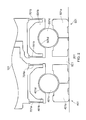
- FIG. 2 shows an enlarged schematic view of the bearing arrangement of FIG. 1 , in an unloaded condition
- FIG. 3 shows the bearing arrangement of FIG. 2 , in a part-loaded condition
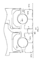
- FIGS. 4 and 5 show the bearing arrangement of FIG. 2 , in a loaded condition
- FIGS. 6 and 7 show alternative embodiments of the bearing arrangement
- FIGS. 8 and 9 show results of tests conducted on simulated bearing arrangements
- FIGS. 10 and 11 show two bearings individually mounted on a set-up jig
- FIGS. 12 a - d show plots of load versus displacement relating to the bearings of FIGS. 10 and 11 ;
- FIG. 13 shows both the bearings of FIGS. 10 and 11 mounted on the set-up jig.
- FIG. 14 shows the bearings of FIGS. 10 and 11 installed in a gas turbine engine.
- FIG. 1 shows a half-section of a bearing housing 101 of a gas turbine engine.
- the engine is a three-shaft gas turbine engine of an aircraft.
- a shaft 201 of the engine extends through the generally-annular bearing housing 101 and is supported by a location bearing arrangement 301 .
- the shaft connects a high pressure turbine and a high pressure compressor (not shown) of the engine.
- the location bearing arrangement 301 comprises first and second thrust bearings 401 , 501 , each of which includes an inner race 401 a , 501 a and an outer race 401 b , 501 b , between which a plurality of rolling elements 401 c , 501 c is disposed in a cage (not shown).
- the rolling elements 401 c , 501 c are balls.
- each of the first and second thrust bearings 401 , 501 is a single-row bearing of the deep-groove type.
- the inner races 401 a , 501 a and the outer races 401 b , 501 b comprise M50NiL steel and the rolling elements 401 c , 501 c comprise M50 steel.
- the inner races 401 a , 501 a of the first and second thrust bearings 401 , 501 are mounted on the shaft 201 and are separated by an axial gap 601 .
- the axial gap 601 has an axial dimension of 5 mm.
- the outer races 401 b , 501 b of the first and second thrust bearings 401 , 501 are each supported by resilient elements, in this embodiment respective pairs of generally flat, radially-extending sheets, or diaphragms 701 a , 701 b , which are secured to the bearing housing 101 .
- the diaphragms 701 a , 701 b are constructed from stainless steel.
- each thrust bearing 401 , 501 there exists a clearance gap 401 d , 501 d between the rolling elements 401 c , 501 c , and the inner race 401 a , 501 a and the outer race 401 b , 501 b .
- the clearance gaps 401 d , 501 d provide free “play” or axial float in the first and second thrust bearings 401 , 501 .
- the axial clearance gap 401 d in the first thrust bearing 401 has a maximum size of 1.00 mm and the axial clearance gap 501 d in the second thrust bearing 501 has a maximum size of 1.01 mm.
- the shaft 201 is being driven by the high pressure turbine to rotate about its longitudinal axis.
- the shaft 201 is moving axially (from right to left as indicated by the arrow), relative to the static bearing housing 101 , under a net aerodynamic force between the high pressure turbine and the high pressure compressor.
- the inner races 401 a , 501 a of the first and second thrust bearings 401 , 501 (which are mounted to the shaft 201 ) come into contact with the respective rolling elements 401 c , 501 c at respective contact points 401 e , 501 e .
- the rolling elements 401 c come into contact with the outer race 401 b at contact points 401 f .
- an axial thrust load F is exerted on, and transmitted through, the first thrust bearing 401 by the shaft 201 . Due to the aforementioned difference in the size of the clearance gaps 401 d , 501 d in the first and second thrust bearings 401 , 501 , the clearance gap 501 d of the second thrust bearing 501 is not yet closed but is reduced in size (to 10 microns).
- the force exerted at the contact points 401 f , by the rolling elements 401 c on the outer race 401 b of the first thrust bearing 401 is sufficient to overcome the resistance (stiffness) of the diaphragms 701 a which support the first thrust bearing 401 .
- the diaphragms 701 a begin to elastically deform (bend or deflect) and the outer race 401 b of the first thrust bearing 401 is axially displaced along with the moving shaft 201 (leftwards as shown in FIG. 4 ).
- the (10 micron) clearance gap 501 d in the second thrust bearing 501 is closed as the rolling elements 501 c of the second thrust bearing 501 are brought into contact with the respective outer race 501 b at contact points 501 f .
- the deformation of the diaphragms 701 a which support the first thrust bearing 401 , enables the second thrust bearing 501 to take up a share of the axial thrust load F imposed by the shaft 201 .
- the second thrust bearing 501 may be sufficiently loaded that skidding of the rolling elements 501 c may be prevented.
- the axial thrust load F further overcomes the resistance (stiffness) of the diaphragms 701 b which support the second thrust bearing 501 , causing these diaphragms 701 b to begin to elastically deform (bend or deflect) and the outer race 501 b of the second thrust bearing 501 to be axially displaced along with the shaft 201 (also leftwards as shown in FIG. 5 ).
- the load is progressively shared between the first and second thrust bearings 401 , 501 until the thrust bearings 401 , 501 carry an equal, or near-equal, share of the axial thrust load F.
- the ability of the diaphragms 701 a , 701 b to distribute the axial thrust load F between the first and second thrust bearings 401 , 501 means that relatively large geometrical variations and/or differential expansions between the thrust bearings 401 , 501 may be tolerated. For example, as will be discussed further herein below, it has been found that the load sharing bearing arrangement 301 can accommodate differences in the thrust bearings 401 , 501 of about 40 microns.
- the diaphragms 701 a , 701 b are in a neutral or unbiased condition.
- the resistance offered by the diaphragms 701 a , 701 b when in the deformed or biased condition ensures that the respective first and second thrust bearings 401 , 501 remain loaded without skidding of the respective rolling elements 401 c , 501 c .
- the energy stored therein is available to return the diaphragms 701 a , 701 b toward, and eventually to, their original (neutral) positions when the axial thrust load F is reduced, and eventually removed, as the shaft 201 reverses its direction of travel (rightwards in FIGS. 3 to 5 ).
- each diaphragm 701 a , 701 b has a constant thickness of 1.219 mm and a constant radial dimension (height) of 10.0 mm.
- FIGS. 4 and 5 show the diaphragms 701 a , 701 b being deformed only at their ends, it will be understood that deformation may occur across the faces of the diaphragms 701 c - d , for example such as to present a generally curved or ‘S’ shaped radial section.
- the bearing arrangement 301 described herein above comprises two diaphragms 701 a , 701 b supporting each of the first and second thrust bearings 401 , 501
- other embodiments may comprise any number of supporting resilient elements.
- one resilient element per thrust bearing 401 , 501 may be sufficient to enable load sharing between the thrust bearings 401 , 501 .
- the resilient elements may support axially-central portions of the respective outer races 401 b , 501 b of the first and second thrust bearings 401 , 501 .
- each of the first and second thrust bearings 401 , 501 may be supported by more than two resilient elements.
- the resilient elements may be arranged in pairs or groups.
- an embodiment shown in FIG. 6 comprises four diaphragms 701 a - d per thrust bearing 401 , 501 , which arrangement reduces both the stiffness and shear stress without increasing the bending stress, compared to a two-diaphragm-per-bearing configuration.
- one or more of the diaphragms include holes which extend around the circumference of the diaphragm.
- the holes may optimise stress and deflection and/or enable fluid flows over the outer races 401 b , 501 b of the thrust bearings 401 , 501 .
- the resilient elements which support the first and second thrust bearings 401 , 501 , comprise beams or radial fingers. Compared to diaphragms, radial fingers may provide greater flexibility, albeit with higher stress (for a given thickness) because the radial fingers do not transmit any hoop loads.
- the resilient elements are angularly offset from the perpendicular such as to have an axial component as well as a radial component.
- the resilient elements may be slanted or inclined from an imaginary line which extends perpendicular to the longitudinal axis of the shaft 201 .
- the resilient elements may form a tapered or conical shape. Such configurations may provide relatively high stiffness (resilience) with a small radial dimension, giving a particularly compact arrangement.
- the resilient elements are curved or dished, such as to comprise a non-linear radial section. In this way the progression of the elastic deformation under load may be controlled, for example to be non-linear.
- the resilient elements are constructed from a titanium alloy.
- the resilient elements comprise a nickel alloy, or a ceramic.
- the resilient elements may be constructed from a super elastic material or alloy, i.e. a material which may undergo an elastic (reversible) response to an applied stress, caused by a phase transformation between the austenitic and martensitic phases of a crystal.
- the overall stiffness of the resilient elements differs between the first and second thrust bearings 401 , 501 .
- the diaphragms 701 a which support the first thrust bearing 401 are of different thickness and/or material compared with the diaphragms 701 b which support the second thrust bearing 501 .
- the diaphragms 701 a , 701 b supporting any one thrust bearing 401 , 501 may be of different thickness and/or material compared to one another. These differences may enable better control of the load sharing between the first and second thrust bearings 401 , 501 .
- the axial gap 601 has an axial dimension of anything up to about 25 mm, while in other embodiments the axial dimension exceeds 25 mm.
- an optional spacer 603 is disposed in the axial gap 601 between the inner races 401 a , 501 a of the first and second thrust bearings 401 , 501 .
- the spacer 603 is fitted during assembly of the bearing arrangement 301 , after installation on the shaft 201 of the inner race 401 a of the first thrust bearing 401 and prior to installation on the shaft 201 of the inner race 501 a of the second thrust bearing 501 .
- the thickness T of the spacer 603 is selected to be sufficient to bring the rolling elements 401 c , 501 c of each of the first and second thrust bearings 401 , 501 into engagement with the respective inner races 401 a , 501 a at contact points 401 e , 501 e and the respective outer races 401 b , 501 b at contact points 401 f , 501 f . That is, the spacer 603 ensures the closure (or at least part-closure) of the clearance gaps 401 d , 501 d to take up the free play or axial float in the first and second thrust bearings 401 , 501 , prior to the application of a significant thrust load from the shaft 201 during engine operation. In this way, the likelihood of skidding of unloaded (or lightly loaded) thrust bearings 401 , 501 may be reduced.
- first and second thrust bearings 401 , 501 are more flexible than the other, for instance due to small manufacturing differences between the diaphragms 701 a , 701 b , the more flexible thrust bearing 401 , 501 may be arranged to engage first to give better load sharing over the operating range.
- the resilient elements and the upper races 401 b , 501 b are of unitary construction.
- the inner races 401 a , 501 a are made integral with the shaft 201 , for example machined on the shaft 201 .
- bearing arrangement 301 described herein above comprises ball-type roller bearings
- the invention is generally applicable to all types of bearings which take a thrust load.
- roller bearings comprising inclined or tapered cylindrical rolling elements, and hydrostatic or hydrodynamic thrust bearings.
- the invention is not limited to embodiments comprising two thrust bearings but may comprise any number of thrust bearings, for example three or four thrust bearings.
- the present inventors constructed a rig for testing a thrust bearing arrangement which was representative of the embodiments described herein above.
- the rig was configured to accommodate a spacer on a shaft between first and second thrust bearings and a range of spacers of different thickness were used to simulate geometrical variations (manufacturing and operational differences) between the two thrust bearings to determine the effect on load sharing.
- FIGS. 8 and 9 contain representative results of rig tests conducted using steel diaphragms as the supporting resilient elements.
- FIG. 8 shows the effect of different spacer thickness on the load share, effectively equating to manufacturing and operation variances of +/ ⁇ 0.05 mm from the optimum.
- FIG. 9 shows the load share achieved at three operating conditions (idle, cruise, take off) for a representative aircraft engine, demonstrating a tolerance band (“design space”) of 0.025 mm whilst remaining within a 60:40 load share at all conditions. Subsequent testing has indicated that a 0.04 mm design space can be achieved with single flexible elements per thrust bearing and may be improved further with multiple flexible elements per thrust bearing.
- the axial displacement of the first and second thrust bearings 401 , 501 which is allowed by the deformation of the resilient elements (e.g. diaphragms or radial fingers) further provides for the determination of the individual and total axial loads on the bearings 401 , 501 , as will now be described.
- the resilient elements e.g. diaphragms or radial fingers
- FIG. 10 shows a first thrust bearing 401 including an inner race 401 a and an outer race 401 b , between which a plurality of rolling elements 401 c is disposed in a cage (not shown) with an axial clearance gap 401 d between the rolling elements 401 c and the inner and outer races 401 a , 401 b .
- the rolling elements 401 c are balls.
- the first thrust bearing 401 is a single-row bearing of the deep-groove type.
- the inner race 401 a and the outer race 401 b comprise M50NiL steel and the rolling elements 401 c comprise M50 steel.
- a generally-annular bearing carrier 403 of the first thrust bearing 401 is here mounted to a support face 801 a of a set-up jig, or slave stand 801 .
- the support face 801 a provides a common datum point D, as will be further discussed herein below.
- the outer race 401 b of the first thrust bearing 401 is supported on the bearing carrier 403 by resilient elements, in this embodiment a pair of generally flat, radially-extending sheets, or diaphragms 701 a , which are secured to the bearing carrier 403 at their radial peripheries.
- the diaphragms 701 a are constructed from stainless steel.
- the first thrust bearing 401 is arranged on the slave stand 801 in an axially horizontal configuration, in order to prevent its own weight causing load maldistribution, high local loads, and friction.
- the first thrust bearing 401 is also disposed on a dummy shaft (not shown) of the slave stand 801 .
- a small axial load L 1 is applied to the inner race 401 a (in this case from right to left as indicated by the arrow in FIG. 10 ) in order to seat the first thrust bearing 401 . That is, the applied load causes the inner race 401 a to move axially, relative to both the slave stand 801 and the outer race 401 b , so as to close the axial clearance gap 401 d between the rolling elements 401 c and the inner and outer races 401 a , 401 b and remove any free “play” or axial float from the first thrust bearing 401 .
- the inner race 401 a may be rotated to assist in seating the first thrust bearing 401 .
- the axial load L 1 is then gradually increased, in order to simulate a thrust load on the first thrust bearing 401 .
- the force exerted, by the rolling elements 401 c on the outer race 401 b is sufficient to overcome the resistance (stiffness) of the diaphragms 701 a which support the first thrust bearing 401 .
- the diaphragms 701 a begin to elastically deform (bend or deflect) and the outer race 401 b is axially displaced (not shown in FIG. 10 ) along with the inner race 401 a , the axial displacements becoming greater as the axial load L 1 is progressively increased.
- the axial distances D 401 a , D 401 b of the respective end faces of the inner and outer races 401 a , 401 b , from the common datum point D are measured and recorded. From these measurements, the respective axial displacements d 401 a , d 401 b (not shown) of the inner and outer races 401 a , 401 b are calculated and recorded at selected values of axial load L 1 . In this way, a record is provided of a range of axial forces and the axial displacements d 401 a , d 401 b of the inner and outer races 401 a , 401 b which correspond to those forces.
- the first thrust bearing 401 and its bearing carrier 403 are removed from the slave stand 801 .
- the second thrust bearing 501 which is of a similar type to the first thrust bearing 401 .
- the second thrust bearing 501 includes an inner race 501 a and an outer race 501 b , between which a plurality of rolling elements 501 c is disposed in a cage (not shown) with an axial clearance gap 501 d between the rolling elements 501 c and the inner and outer races 501 a , 501 b .
- the rolling elements 501 c are balls.
- the second thrust bearing 501 is a single-row bearing of the deep-groove type.
- the inner race 501 a and the outer race 501 b comprise M50NiL steel and the rolling elements 501 c comprise M50 steel.
- the second thrust bearing 501 is arranged on the same slave stand 801 as has been described herein above. That is, a generally-annular bearing carrier 503 of the second thrust bearing 501 is mounted to the support face 801 a (providing common datum point D) of the slave stand 801 .
- the outer race 501 b of the second thrust bearing 501 is supported on the bearing carrier 503 by resilient elements, in this embodiment a pair of generally flat, radially-extending sheets, or diaphragms 701 b , which are secured to the bearing carrier 503 at their radial peripheries.
- the diaphragms 701 b are constructed from stainless steel.
- the diaphragms 701 b are generally similar to the diaphragms 701 a which support the first thrust bearing 401 as described herein above.
- the second thrust bearing 501 is arranged on the slave stand 801 in an axially horizontal configuration, in order to prevent its own weight causing load maldistribution, high local loads, and friction.
- the second thrust bearing 501 is also disposed on a dummy shaft (not shown) of the slave stand 801 .
- a small axial load L 2 is applied to the inner race 501 a (in this case from right to left as indicated by the arrow in FIG. 11 ) in order to seat the second thrust bearing 501 . That is, the applied load causes the inner race 501 a to move axially, relative to both the slave stand 801 and the outer race 501 b , so as to close the axial clearance gap 501 d between the rolling elements 501 c and the inner and outer races 501 a , 501 b and remove any free “play” or axial float from the second thrust bearing 501 .
- the inner race 501 a may be rotated to assist in seating the second thrust bearing 501 .
- the axial load L 2 is then gradually increased, in order to simulate a thrust load on the second thrust bearing 501 .
- the force exerted, by the rolling elements 501 c on the outer race 501 b is sufficient to overcome the resistance (stiffness) of the diaphragms 701 b which support the second thrust bearing 501 .
- the diaphragms 701 b begin to elastically deform (bend or deflect) and the outer race 501 b is axially displaced (not shown in FIG. 11 ) along with the inner race 501 a , the axial displacements becoming greater as the axial load L 2 is progressively increased.
- the axial distances D 501 a , D 501 b of the respective end faces of the inner and outer races 501 a , 501 b , from the common datum point D are measured and recorded. From these measurements, the respective axial displacements d 501 a , d 501 b (not shown) of the inner and outer races 501 a , 501 b are calculated and recorded at selected values of axial load L 2 . In this way, a record is provided of a range of axial forces and the axial displacements d 501 a , d 501 b of the inner and outer races 501 a , 501 b which correspond to those forces.
- the second thrust bearing 501 and its bearing carrier 503 remain mounted on the slave stand 801 .
- each of the recorded displacements d 401 a , d 401 b , d 501 a , d 501 b represents the average of numerous measurements taken at a plurality of locations around the circumferences of the respective end faces of each of the inner and outer races 401 a , 401 b , 501 a , 501 b .
- Measurement is by conventional means, for example using a displacement probe.
- the recorded measurements provide data sets, which may be in the form of graphs showing load versus displacement, or look-up tables, or some other convenient format as will be apparent to the skilled reader.
- the data sets may be digitised and stored in a computer or on a computer-readable medium.
- the maximum value of the axial loads L 1 , L 2 applied in the slave stand 801 is 65 kN, which value corresponds to a typical design load of the first and second bearings 401 , 501 .
- the lesser axial loads L 1 , L 2 which are applied to seat the respective first and second bearings 401 , 501 here take a value of about 650 N, i.e. one percent of the 65 kN design load.
- one-per-cent-of-design-load is only a rough rule of thumb, and some other value of axial load may be required in order to seat the first and second bearings 401 , 501 .
- FIGS. 12 a and 12 b are load-versus-displacement plots relating to the above-described first and second bearings 401 , 501 .
- the graphs show the axial displacements d 401 a , d 401 b , d 501 a , d 501 b of the respective inner and outer races 401 a , 401 b , 501 a , 501 b , as well as the total displacement (summation of the displacements d 401 a , d 401 b , d 501 a , d 501 b of the respective inner and outer races 401 a , 401 b , 501 a , 501 b ), of each of the thrust bearings 401 , 501 on the slave stand 801 .
- FIG. 12 c is a load-versus-displacement plot which shows the total displacement of the first and second thrust bearings 401 , 501 .
- the low load range of FIG. 12 c is shown in higher-resolution in FIG. 12 d .
- the plots of FIGS. 12 c and 12 d in particular may be used as “calibration curves” for determining the in-service axial loads on the first and second thrust bearings 401 , 501 , as will be described herein below.
- the total axial displacement of the second thrust bearing 501 is greater than the total axial displacement of the first thrust bearing 401 at any given axial load.
- the first thrust bearing 401 is stiffer (less flexible) than the second thrust bearing 501 .
- This difference in stiffness is to be expected, for example because of geometrical variations (manufacturing tolerances) between the first and second thrust bearings 401 , 501 .
- the first thrust bearing 401 may be less stiff (more flexible) than the second thrust bearing 501 .
- the first thrust bearing 401 is refitted to the slave stand 801 alongside the second thrust bearing 501 .
- the first and second thrust bearings 401 , 501 are separated by an axial gap, or clearance gap 901 .
- the axial dimension D 901 of the clearance gap 901 is equal to the difference between the above-mentioned axial distances D 401 a , D 501 a of the respective inner races 401 a , 501 a from the common datum point D when the first and second bearings 401 , 501 have been properly seated.
- in-service load sharing should begin at an axial load L 3 (shown acting from right to left in FIG. 13 ) of between about 1 kN and 4 kN.
- a spacer 903 is inserted in the clearance gap 901 between the first and second thrust bearings 401 , 501 .
- the thickness T of the spacer 903 i.e. its axial dimension
- the thickness T of the spacer 903 is selected to be smaller than the axial dimension D 901 of the clearance gap 901 .
- the load-versus-displacement data sets enable the first and second bearings 401 , 501 to be configured such that they will commence to share an in-service axial load at an appropriate load level chosen by the designer.
- the first and second bearings 401 , 501 may be installed ready for service, for example in a gas turbine engine of an aircraft, as shown in FIG. 14 .
- the inner races 401 a , 501 a of the first and second thrust bearings 401 , 501 are mounted on a shaft 201 of the engine, the shaft 201 connecting a high pressure turbine and a high pressure compressor (not shown) of the engine in the manner described herein above.
- a spacer 903 is disposed in an axial clearance gap 901 between the inner races 401 a , 501 a.
- a first displacement probe, or sensor 405 is disposed adjacent a front end face of the outer race 401 b of the first thrust bearing 401
- a second displacement probe, or sensor 505 is disposed adjacent a rear end face of the outer race 501 b of the second thrust bearing 501 .
- the terms front and rear relate to the direction of gas flow through the engine, which is from left to right in FIG. 14 .
- the displacement sensors 405 , 505 are connected to a processor 1001 which is configured to receive displacement measurements therefrom.
- the processor 1001 is additionally configured to have access to the above-mentioned data sets relating to the first and second thrust bearings 401 , 501 .
- the individual loads on each of the first and second thrust bearings 401 , 501 , and optionally the total load are determined by the processor 1001 using the calibration curves of the respective first and second data sets ( FIGS. 12 c and 12 d ).
- the loads could alternatively be determined manually from the measured displacements without the use of the processor 1001 .
- This knowledge of the individual operating loads can provide confidence that the first and second thrust bearings 401 , 501 are sharing the in-service axial load as intended.
- the loads on the thrust bearings 401 , 501 may be monitored throughout the operating range of the gas turbine engine and the detection of bearing failures or anomalies may be indicated by either sudden or gradual changes in the loads.
- the condition of the bearings may be monitored, and problems may be better predicted and maintenance may be more accurately scheduled.
- systemic problems e.g. in the air systems of the gas turbine engine, which tend to manifest themselves as a change in load on the bearings, may be more quickly identified.
- displacements of the outer races 401 b , 501 b of the order of 0.4 mm as described herein above are conveniently measured using conventional measuring devices, for example eddy current, laser, optical, or linear variable differential transformer (LVDT) devices.
- LVDT linear variable differential transformer
- Particularly accurate measurements may be achieved if the measuring devices are positioned close to the radially-outer peripheries of the resilient elements (e.g. diaphragms 701 a , 701 b ) because this will minimise any effects on measurement accuracy of differential expansions between the outer races 401 b , 501 b and the bearing carriers 403 , 503 .
- the measuring devices may be positioned in various locations, as long as they are able to detect the displacement of the outer races 401 b , 501 b . Furthermore, the same or additional measuring devices may be arranged to measure the displacements of the inner races 401 a , 501 a.
- first and second thrust bearings 401 , 501 may be set up for displacement measurement on the slave stand 801 individually and sequentially as described herein above, alternatively they may be set up on the slave stand 801 simultaneously. Or, the slave stand 801 may be omitted and instead the first and second thrust bearings 401 , 501 may be set up for displacement measurement in-situ in their operating environment, for example in a gas turbine engine of an aircraft, some common datum point being provided from which to measure the respective axial distances D 401 a , D 401 b , D 501 a , D 501 b.
- the described load-determination method is appropriate for any and all of the embodiments of bearing arrangements described herein above. Furthermore, while the specifically described embodiment relates to the measurement of axial displacement of first and second thrust bearings 401 , 501 , it will be understood that the load-determination method is also suitable for measuring the axial displacement of a single, flexibly supported thrust bearing and determining the load on that single thrust bearing.
- the invention is equally applicable to a two-shaft or single-shaft gas turbine engine.
- the invention is appropriate for gas turbine engines used for other purposes than to power an aircraft, for example industrial gas turbine engines or marine gas turbine engines.
- the invention is not only relevant to gas turbine engines but has wider utility.
- the claimed bearing arrangement may be made relatively compact, it may be suitable for application in any rotor, for example of a type used in oil and gas drilling, where an axial load is close to or beyond the capabilities of a single bearing. In these situations, the ability of a bearing to carry loads is limited at high shaft speeds due to centrifugal loads on the rolling elements; hence it is not possible merely to increase the diameter of the bearing in order to cope with the loads placed upon it.
Landscapes
- Engineering & Computer Science (AREA)
- General Engineering & Computer Science (AREA)
- Mechanical Engineering (AREA)
- Physics & Mathematics (AREA)
- General Physics & Mathematics (AREA)
- Rolling Contact Bearings (AREA)
- Support Of The Bearing (AREA)
Priority Applications (1)
| Application Number | Priority Date | Filing Date | Title |
|---|---|---|---|
| US15/264,187 US9658132B2 (en) | 2014-03-19 | 2016-09-13 | Bearing arrangement and method |
Applications Claiming Priority (2)
| Application Number | Priority Date | Filing Date | Title |
|---|---|---|---|
| GB1404876.3 | 2014-03-19 | ||
| GBGB1404876.3A GB201404876D0 (en) | 2014-03-19 | 2014-03-19 | Bearing arrangement and method |
Related Child Applications (1)
| Application Number | Title | Priority Date | Filing Date |
|---|---|---|---|
| US15/264,187 Division US9658132B2 (en) | 2014-03-19 | 2016-09-13 | Bearing arrangement and method |
Publications (2)
| Publication Number | Publication Date |
|---|---|
| US20150267744A1 US20150267744A1 (en) | 2015-09-24 |
| US9470262B2 true US9470262B2 (en) | 2016-10-18 |
Family
ID=50635005
Family Applications (2)
| Application Number | Title | Priority Date | Filing Date |
|---|---|---|---|
| US14/631,245 Active US9470262B2 (en) | 2014-03-19 | 2015-02-25 | Bearing arrangement and method |
| US15/264,187 Active US9658132B2 (en) | 2014-03-19 | 2016-09-13 | Bearing arrangement and method |
Family Applications After (1)
| Application Number | Title | Priority Date | Filing Date |
|---|---|---|---|
| US15/264,187 Active US9658132B2 (en) | 2014-03-19 | 2016-09-13 | Bearing arrangement and method |
Country Status (3)
| Country | Link |
|---|---|
| US (2) | US9470262B2 (fr) |
| EP (1) | EP2921655A3 (fr) |
| GB (1) | GB201404876D0 (fr) |
Cited By (4)
| Publication number | Priority date | Publication date | Assignee | Title |
|---|---|---|---|---|
| US20160160911A1 (en) * | 2014-12-09 | 2016-06-09 | Rolls-Royce Plc | Bearing structure |
| US10156159B1 (en) | 2017-08-22 | 2018-12-18 | General Electric Company | Squeeze film damper for a gas turbine engine |
| US10174788B2 (en) | 2016-02-03 | 2019-01-08 | Rolls-Royce Plc | Bearing arrangements |
| US11453487B2 (en) * | 2018-06-28 | 2022-09-27 | Sikorsky Aircraft Corporation | Redundant helicopter pitch change bearing |
Families Citing this family (12)
| Publication number | Priority date | Publication date | Assignee | Title |
|---|---|---|---|---|
| GB201421880D0 (en) | 2014-12-09 | 2015-01-21 | Rolls Royce Plc | Bearing structure |
| US10458270B2 (en) | 2015-06-23 | 2019-10-29 | United Technologies Corporation | Roller bearings for high ratio geared turbofan engine |
| US9956985B2 (en) * | 2016-02-16 | 2018-05-01 | Steering Solutions Ip Holding Corporation | Steering shaft assembly |
| US10557503B2 (en) * | 2016-06-16 | 2020-02-11 | Honeywell International Inc. | Bearing mount and preload assembly |
| RU2623674C1 (ru) * | 2016-08-04 | 2017-06-28 | Публичное акционерное общество "Уфимское моторостроительное производственное объединение" ПАО "УМПО" | Радиально-упорная опора ротора газотурбинного двигателя |
| US9932986B2 (en) * | 2016-08-05 | 2018-04-03 | United Technologies Corporation | Variable preloaded duplex thrust bearing system for a geared turbofan engine |
| US20180086364A1 (en) * | 2016-09-23 | 2018-03-29 | Mando Corporation | Steering column for vehicle |
| EP3330493B1 (fr) * | 2016-12-02 | 2019-05-01 | Rolls-Royce Deutschland Ltd & Co KG | Système de commande et procédé pour moteur de turbine à gaz |
| US10882070B2 (en) | 2017-03-28 | 2021-01-05 | Steering Solutions Ip Holding Corporation | Method of manufacturing a steering shaft assembly |
| JP6876030B2 (ja) * | 2018-12-04 | 2021-05-26 | 本田技研工業株式会社 | 転がり軸受固定構造 |
| WO2021126314A1 (fr) | 2019-12-19 | 2021-06-24 | The Timken Company | Palier à rouleaux en série dissemblables coniques, à poussée, empilés |
| CN115808310B (zh) * | 2023-02-09 | 2023-05-12 | 哈尔滨科锐同创机模制造有限公司 | 一种应用于轴承试验的试验参数标定方法和系统 |
Citations (23)
| Publication number | Priority date | Publication date | Assignee | Title |
|---|---|---|---|---|
| GB191127465A (en) * | 1911-12-07 | 1912-09-05 | Thomas Cooper | Improvements in Thrust Bearings. |
| GB965465A (en) | 1961-08-10 | 1964-07-29 | Rolls Royce | Improvements relating to compressor thrust bearings |
| US3738719A (en) * | 1970-08-04 | 1973-06-12 | Snecma | Ball bearing |
| GB1344318A (en) | 1970-10-27 | 1974-01-23 | Snecma | Ball bearing |
| DE2718861A1 (de) * | 1977-04-28 | 1978-11-02 | Josef Jasper | Mehrfache drucklagerung |
| EP0010371A1 (fr) * | 1978-09-29 | 1980-04-30 | Syntex (U.S.A.) Inc. | Cartouche avec turbine et instrument dentaire à main équipé de celle-ci |
| US4501454A (en) | 1983-10-28 | 1985-02-26 | Dresser Industries, Inc. | Method of distributing load among stacked bearings |
| US4578018A (en) | 1983-06-20 | 1986-03-25 | General Electric Company | Rotor thrust balancing |
| US4676667A (en) * | 1985-03-13 | 1987-06-30 | Nissan Motor Co., Ltd. | Variable preload shaft bearing for turbocharger |
| US5316393A (en) | 1992-09-30 | 1994-05-31 | The United States Of America As Represented By The Secretary Of The Navy | Duplex rolling element bearing mounting for ensuring preload control |
| US5749700A (en) * | 1996-07-17 | 1998-05-12 | Allison Engine Company, Inc. | High speed, high temperature hybrid magnetic thrust bearing |
| US5836739A (en) | 1995-03-17 | 1998-11-17 | Rolls-Royce Plc | Gas turbine engine |
| JPH1162953A (ja) | 1997-08-08 | 1999-03-05 | Nissan Motor Co Ltd | 軸受装置 |
| US5977677A (en) | 1996-06-26 | 1999-11-02 | Allison Engine Company | Combination bearing for gas turbine engine |
| US6325546B1 (en) * | 1999-11-30 | 2001-12-04 | General Electric Company | Fan assembly support system |
| US20040170350A1 (en) * | 2001-05-15 | 2004-09-02 | Mccallum Steven Murray | Resiliently mounted bearing |
| US6964211B1 (en) * | 2000-10-06 | 2005-11-15 | Trw Inc. | Steering column with improved housing |
| EP2194238A1 (fr) | 2008-12-08 | 2010-06-09 | Rolls-Royce plc | Disposition de butées |
| WO2011139310A2 (fr) | 2009-12-29 | 2011-11-10 | Rolls-Royce Corporation | Moteur à turbine a gaz et système de palier à éléments roulants à grande vitesse |
| US8083472B2 (en) | 2007-10-20 | 2011-12-27 | Rolls-Royce Plc | Shaft bearing arrangement |
| US20130129504A1 (en) | 2011-11-18 | 2013-05-23 | Rolls-Royce Deutschland Ltd & Co Kg | Bearing device and turbomachine having a bearing device |
| US20130280063A1 (en) | 2012-04-23 | 2013-10-24 | General Electric Company | Dual spring bearing support housing |
| EP2821657A1 (fr) | 2013-06-18 | 2015-01-07 | Rolls-Royce plc | Agencement de support |
Family Cites Families (1)
| Publication number | Priority date | Publication date | Assignee | Title |
|---|---|---|---|---|
| DE4112253A1 (de) * | 1991-04-15 | 1992-10-22 | Skf Gmbh | Waelzlagerung |
-
2014
- 2014-03-19 GB GBGB1404876.3A patent/GB201404876D0/en not_active Ceased
-
2015
- 2015-02-24 EP EP15156324.4A patent/EP2921655A3/fr not_active Withdrawn
- 2015-02-25 US US14/631,245 patent/US9470262B2/en active Active
-
2016
- 2016-09-13 US US15/264,187 patent/US9658132B2/en active Active
Patent Citations (24)
| Publication number | Priority date | Publication date | Assignee | Title |
|---|---|---|---|---|
| GB191127465A (en) * | 1911-12-07 | 1912-09-05 | Thomas Cooper | Improvements in Thrust Bearings. |
| GB965465A (en) | 1961-08-10 | 1964-07-29 | Rolls Royce | Improvements relating to compressor thrust bearings |
| US3738719A (en) * | 1970-08-04 | 1973-06-12 | Snecma | Ball bearing |
| GB1344318A (en) | 1970-10-27 | 1974-01-23 | Snecma | Ball bearing |
| DE2718861A1 (de) * | 1977-04-28 | 1978-11-02 | Josef Jasper | Mehrfache drucklagerung |
| EP0010371A1 (fr) * | 1978-09-29 | 1980-04-30 | Syntex (U.S.A.) Inc. | Cartouche avec turbine et instrument dentaire à main équipé de celle-ci |
| US4578018A (en) | 1983-06-20 | 1986-03-25 | General Electric Company | Rotor thrust balancing |
| US4501454A (en) | 1983-10-28 | 1985-02-26 | Dresser Industries, Inc. | Method of distributing load among stacked bearings |
| US4676667A (en) * | 1985-03-13 | 1987-06-30 | Nissan Motor Co., Ltd. | Variable preload shaft bearing for turbocharger |
| US5316393A (en) | 1992-09-30 | 1994-05-31 | The United States Of America As Represented By The Secretary Of The Navy | Duplex rolling element bearing mounting for ensuring preload control |
| US5836739A (en) | 1995-03-17 | 1998-11-17 | Rolls-Royce Plc | Gas turbine engine |
| US5977677A (en) | 1996-06-26 | 1999-11-02 | Allison Engine Company | Combination bearing for gas turbine engine |
| US5749700A (en) * | 1996-07-17 | 1998-05-12 | Allison Engine Company, Inc. | High speed, high temperature hybrid magnetic thrust bearing |
| JPH1162953A (ja) | 1997-08-08 | 1999-03-05 | Nissan Motor Co Ltd | 軸受装置 |
| US6325546B1 (en) * | 1999-11-30 | 2001-12-04 | General Electric Company | Fan assembly support system |
| US6964211B1 (en) * | 2000-10-06 | 2005-11-15 | Trw Inc. | Steering column with improved housing |
| US20040170350A1 (en) * | 2001-05-15 | 2004-09-02 | Mccallum Steven Murray | Resiliently mounted bearing |
| US8083472B2 (en) | 2007-10-20 | 2011-12-27 | Rolls-Royce Plc | Shaft bearing arrangement |
| EP2194238A1 (fr) | 2008-12-08 | 2010-06-09 | Rolls-Royce plc | Disposition de butées |
| WO2011139310A2 (fr) | 2009-12-29 | 2011-11-10 | Rolls-Royce Corporation | Moteur à turbine a gaz et système de palier à éléments roulants à grande vitesse |
| US20120111024A1 (en) * | 2009-12-29 | 2012-05-10 | Kachinski Paul A | Gas turbine engine and high speed rolling element bearing |
| US20130129504A1 (en) | 2011-11-18 | 2013-05-23 | Rolls-Royce Deutschland Ltd & Co Kg | Bearing device and turbomachine having a bearing device |
| US20130280063A1 (en) | 2012-04-23 | 2013-10-24 | General Electric Company | Dual spring bearing support housing |
| EP2821657A1 (fr) | 2013-06-18 | 2015-01-07 | Rolls-Royce plc | Agencement de support |
Non-Patent Citations (2)
| Title |
|---|
| Jul. 15, 2015 Partial Search Report issued in European Patent Application No. 15 15 6324. |
| Oct. 20, 2014 Search Report issued in United Kingdom Application No. GB1404876.3. |
Cited By (6)
| Publication number | Priority date | Publication date | Assignee | Title |
|---|---|---|---|---|
| US20160160911A1 (en) * | 2014-12-09 | 2016-06-09 | Rolls-Royce Plc | Bearing structure |
| US9829037B2 (en) * | 2014-12-09 | 2017-11-28 | Rolls-Royce Plc | Bearing structure |
| US10174788B2 (en) | 2016-02-03 | 2019-01-08 | Rolls-Royce Plc | Bearing arrangements |
| US10156159B1 (en) | 2017-08-22 | 2018-12-18 | General Electric Company | Squeeze film damper for a gas turbine engine |
| US10400630B2 (en) | 2017-08-22 | 2019-09-03 | General Electric Company | Squeeze film damper for a gas turbine engine |
| US11453487B2 (en) * | 2018-06-28 | 2022-09-27 | Sikorsky Aircraft Corporation | Redundant helicopter pitch change bearing |
Also Published As
| Publication number | Publication date |
|---|---|
| EP2921655A3 (fr) | 2015-12-09 |
| US9658132B2 (en) | 2017-05-23 |
| US20150267744A1 (en) | 2015-09-24 |
| EP2921655A2 (fr) | 2015-09-23 |
| GB201404876D0 (en) | 2014-04-30 |
| US20170003196A1 (en) | 2017-01-05 |
Similar Documents
| Publication | Publication Date | Title |
|---|---|---|
| US9658132B2 (en) | Bearing arrangement and method | |
| US8727629B2 (en) | Series bearing support apparatus for a gas turbine engine | |
| US10612586B2 (en) | Thrust bearing for a wind turbine | |
| US9651092B2 (en) | Bearing arrangement | |
| US20130108202A1 (en) | Bearing support apparatus for a gas turbine engine | |
| EP3015659B1 (fr) | Turbine à gaz et méthode de détermination des charges sur agencement de palier de turbine à gaz | |
| EP3020987B1 (fr) | Palier angulaire à auto-alignement muni d'éléments à surface toroidale | |
| EP3040568B1 (fr) | Dispositif de palier avec deux roulements juxtaposés et une chambre de pression avec paroi élastique pour précharger les roulements et pour répartir également la charge axiale sur les deux roulements | |
| Żywica et al. | Selected operational problems of high-speed rotors supported by gas foil bearings | |
| Tripp et al. | Eccentricity measurements on a tilting-pad bearing | |
| Wygant et al. | Measured performance of tilting-pad journal bearings over a range of preloads—Part I: static operating conditions | |
| Rimpel et al. | A Rotordynamic, Thermal, and Thrust Load Performance Gas Bearing Test Rig and Test Results for Tilting Pad Journal Bearings and Spiral Groove Thrust Bearings | |
| US11692888B2 (en) | Bearing unit having at least two kinds of sensing elements mounted on a housing | |
| KR20070019910A (ko) | 축하중 측정시스템 | |
| Carter | Measured and Predicted Rotordynamic Coefficients and Static Performance of a Rocker-Pivot Tilt Pad Bearing in Load-on-Pad and Load-Between-Pad Configurations | |
| Ise et al. | Experimental study of small-size air turbo blower supported by externally pressurized conical gas bearings | |
| Chirathadam | Measurements of Drag Torque and Lift Off Speed and Identification of Stiffness and Damping in a Metal Mesh Foil Bearing | |
| Zhao et al. | Measurement of the roller tilt angle in a double-row tapered roller bearing with strain gauges | |
| US10883540B1 (en) | Strain measuring device for bearing compartment | |
| Łagodziński et al. | Influence of intermediate foil on air-foil bearings performance and exploitation properties | |
| Skelley | Rotating Balances Used for Fluid Pump Testing | |
| CN107677475B (zh) | 用于调心滚子轴承偏转检测的检测方法 | |
| Dimofte et al. | Oil wave journal bearing steady-state data from a new test rig | |
| Tipton | Bearing load measurements on a 3-shaft gas turbine | |
| Brown et al. | High Speed Cylindrical Roller Bearing Development |
Legal Events
| Date | Code | Title | Description |
|---|---|---|---|
| AS | Assignment |
Owner name: ROLLS-ROYCE PLC, GREAT BRITAIN Free format text: ASSIGNMENT OF ASSIGNORS INTEREST;ASSIGNORS:GALLIMORE, STEPHEN;FLETCHER, PAUL;WEBSTER, JOHN RICHARD;AND OTHERS;REEL/FRAME:035028/0889 Effective date: 20150113 |
|
| FEPP | Fee payment procedure |
Free format text: PAYOR NUMBER ASSIGNED (ORIGINAL EVENT CODE: ASPN); ENTITY STATUS OF PATENT OWNER: LARGE ENTITY |
|
| STCF | Information on status: patent grant |
Free format text: PATENTED CASE |
|
| MAFP | Maintenance fee payment |
Free format text: PAYMENT OF MAINTENANCE FEE, 4TH YEAR, LARGE ENTITY (ORIGINAL EVENT CODE: M1551); ENTITY STATUS OF PATENT OWNER: LARGE ENTITY Year of fee payment: 4 |
|
| MAFP | Maintenance fee payment |
Free format text: PAYMENT OF MAINTENANCE FEE, 8TH YEAR, LARGE ENTITY (ORIGINAL EVENT CODE: M1552); ENTITY STATUS OF PATENT OWNER: LARGE ENTITY Year of fee payment: 8 |