US9468522B2 - Implant device, sensor module, single-use injector and method for producing an implant device - Google Patents
Implant device, sensor module, single-use injector and method for producing an implant device Download PDFInfo
- Publication number
- US9468522B2 US9468522B2 US14/372,264 US201314372264A US9468522B2 US 9468522 B2 US9468522 B2 US 9468522B2 US 201314372264 A US201314372264 A US 201314372264A US 9468522 B2 US9468522 B2 US 9468522B2
- Authority
- US
- United States
- Prior art keywords
- implant device
- module
- implant
- sensor module
- fastening means
- Prior art date
- Legal status (The legal status is an assumption and is not a legal conclusion. Google has not performed a legal analysis and makes no representation as to the accuracy of the status listed.)
- Expired - Fee Related
Links
- 239000007943 implant Substances 0.000 title claims abstract description 88
- 238000004519 manufacturing process Methods 0.000 title description 6
- 239000000463 material Substances 0.000 claims description 9
- 210000001508 eye Anatomy 0.000 description 9
- 238000000034 method Methods 0.000 description 9
- 230000004410 intraocular pressure Effects 0.000 description 8
- 239000004926 polymethyl methacrylate Substances 0.000 description 4
- 210000005036 nerve Anatomy 0.000 description 3
- 229920003229 poly(methyl methacrylate) Polymers 0.000 description 3
- 229920000642 polymer Polymers 0.000 description 3
- 229920001296 polysiloxane Polymers 0.000 description 3
- 239000011248 coating agent Substances 0.000 description 2
- 238000000576 coating method Methods 0.000 description 2
- 210000004087 cornea Anatomy 0.000 description 2
- 238000011161 development Methods 0.000 description 2
- 230000018109 developmental process Effects 0.000 description 2
- 238000010586 diagram Methods 0.000 description 2
- 208000037265 diseases, disorders, signs and symptoms Diseases 0.000 description 2
- 238000005259 measurement Methods 0.000 description 2
- 238000000465 moulding Methods 0.000 description 2
- 238000012634 optical imaging Methods 0.000 description 2
- -1 poly(methyl methacrylate) Polymers 0.000 description 2
- 229920000052 poly(p-xylylene) Polymers 0.000 description 2
- 210000001525 retina Anatomy 0.000 description 2
- 208000010412 Glaucoma Diseases 0.000 description 1
- 229920005372 Plexiglas® Polymers 0.000 description 1
- 206010039729 Scotoma Diseases 0.000 description 1
- 210000005252 bulbus oculi Anatomy 0.000 description 1
- 239000002775 capsule Substances 0.000 description 1
- 239000004020 conductor Substances 0.000 description 1
- 238000003745 diagnosis Methods 0.000 description 1
- 201000010099 disease Diseases 0.000 description 1
- 239000000017 hydrogel Substances 0.000 description 1
- 230000001771 impaired effect Effects 0.000 description 1
- 230000010189 intracellular transport Effects 0.000 description 1
- 239000002184 metal Substances 0.000 description 1
- 210000001328 optic nerve Anatomy 0.000 description 1
- 238000011369 optimal treatment Methods 0.000 description 1
- 108091008695 photoreceptors Proteins 0.000 description 1
- 239000004033 plastic Substances 0.000 description 1
- 229920003023 plastic Polymers 0.000 description 1
- XLYOFNOQVPJJNP-UHFFFAOYSA-N water Substances O XLYOFNOQVPJJNP-UHFFFAOYSA-N 0.000 description 1
- 229920003176 water-insoluble polymer Polymers 0.000 description 1
- 238000004804 winding Methods 0.000 description 1
Images


Classifications
-
- A—HUMAN NECESSITIES
- A61—MEDICAL OR VETERINARY SCIENCE; HYGIENE
- A61F—FILTERS IMPLANTABLE INTO BLOOD VESSELS; PROSTHESES; DEVICES PROVIDING PATENCY TO, OR PREVENTING COLLAPSING OF, TUBULAR STRUCTURES OF THE BODY, e.g. STENTS; ORTHOPAEDIC, NURSING OR CONTRACEPTIVE DEVICES; FOMENTATION; TREATMENT OR PROTECTION OF EYES OR EARS; BANDAGES, DRESSINGS OR ABSORBENT PADS; FIRST-AID KITS
- A61F2/00—Filters implantable into blood vessels; Prostheses, i.e. artificial substitutes or replacements for parts of the body; Appliances for connecting them with the body; Devices providing patency to, or preventing collapsing of, tubular structures of the body, e.g. stents
- A61F2/02—Prostheses implantable into the body
- A61F2/14—Eye parts, e.g. lenses or corneal implants; Artificial eyes
- A61F2/16—Intraocular lenses
-
- A—HUMAN NECESSITIES
- A61—MEDICAL OR VETERINARY SCIENCE; HYGIENE
- A61B—DIAGNOSIS; SURGERY; IDENTIFICATION
- A61B3/00—Apparatus for testing the eyes; Instruments for examining the eyes
- A61B3/10—Objective types, i.e. instruments for examining the eyes independent of the patients' perceptions or reactions
- A61B3/16—Objective types, i.e. instruments for examining the eyes independent of the patients' perceptions or reactions for measuring intraocular pressure, e.g. tonometers
-
- A—HUMAN NECESSITIES
- A61—MEDICAL OR VETERINARY SCIENCE; HYGIENE
- A61F—FILTERS IMPLANTABLE INTO BLOOD VESSELS; PROSTHESES; DEVICES PROVIDING PATENCY TO, OR PREVENTING COLLAPSING OF, TUBULAR STRUCTURES OF THE BODY, e.g. STENTS; ORTHOPAEDIC, NURSING OR CONTRACEPTIVE DEVICES; FOMENTATION; TREATMENT OR PROTECTION OF EYES OR EARS; BANDAGES, DRESSINGS OR ABSORBENT PADS; FIRST-AID KITS
- A61F2/00—Filters implantable into blood vessels; Prostheses, i.e. artificial substitutes or replacements for parts of the body; Appliances for connecting them with the body; Devices providing patency to, or preventing collapsing of, tubular structures of the body, e.g. stents
- A61F2/02—Prostheses implantable into the body
- A61F2/14—Eye parts, e.g. lenses or corneal implants; Artificial eyes
- A61F2/16—Intraocular lenses
- A61F2/1613—Intraocular lenses having special lens configurations, e.g. multipart lenses; having particular optical properties, e.g. pseudo-accommodative lenses, lenses having aberration corrections, diffractive lenses, lenses for variably absorbing electromagnetic radiation, lenses having variable focus
-
- A—HUMAN NECESSITIES
- A61—MEDICAL OR VETERINARY SCIENCE; HYGIENE
- A61F—FILTERS IMPLANTABLE INTO BLOOD VESSELS; PROSTHESES; DEVICES PROVIDING PATENCY TO, OR PREVENTING COLLAPSING OF, TUBULAR STRUCTURES OF THE BODY, e.g. STENTS; ORTHOPAEDIC, NURSING OR CONTRACEPTIVE DEVICES; FOMENTATION; TREATMENT OR PROTECTION OF EYES OR EARS; BANDAGES, DRESSINGS OR ABSORBENT PADS; FIRST-AID KITS
- A61F2/00—Filters implantable into blood vessels; Prostheses, i.e. artificial substitutes or replacements for parts of the body; Appliances for connecting them with the body; Devices providing patency to, or preventing collapsing of, tubular structures of the body, e.g. stents
- A61F2/02—Prostheses implantable into the body
- A61F2/14—Eye parts, e.g. lenses or corneal implants; Artificial eyes
- A61F2/16—Intraocular lenses
- A61F2/1694—Capsular bag spreaders therefor
-
- A—HUMAN NECESSITIES
- A61—MEDICAL OR VETERINARY SCIENCE; HYGIENE
- A61F—FILTERS IMPLANTABLE INTO BLOOD VESSELS; PROSTHESES; DEVICES PROVIDING PATENCY TO, OR PREVENTING COLLAPSING OF, TUBULAR STRUCTURES OF THE BODY, e.g. STENTS; ORTHOPAEDIC, NURSING OR CONTRACEPTIVE DEVICES; FOMENTATION; TREATMENT OR PROTECTION OF EYES OR EARS; BANDAGES, DRESSINGS OR ABSORBENT PADS; FIRST-AID KITS
- A61F9/00—Methods or devices for treatment of the eyes; Devices for putting in contact-lenses; Devices to correct squinting; Apparatus to guide the blind; Protective devices for the eyes, carried on the body or in the hand
- A61F9/0008—Introducing ophthalmic products into the ocular cavity or retaining products therein
- A61F9/0017—Introducing ophthalmic products into the ocular cavity or retaining products therein implantable in, or in contact with, the eye, e.g. ocular inserts
-
- A—HUMAN NECESSITIES
- A61—MEDICAL OR VETERINARY SCIENCE; HYGIENE
- A61F—FILTERS IMPLANTABLE INTO BLOOD VESSELS; PROSTHESES; DEVICES PROVIDING PATENCY TO, OR PREVENTING COLLAPSING OF, TUBULAR STRUCTURES OF THE BODY, e.g. STENTS; ORTHOPAEDIC, NURSING OR CONTRACEPTIVE DEVICES; FOMENTATION; TREATMENT OR PROTECTION OF EYES OR EARS; BANDAGES, DRESSINGS OR ABSORBENT PADS; FIRST-AID KITS
- A61F2/00—Filters implantable into blood vessels; Prostheses, i.e. artificial substitutes or replacements for parts of the body; Appliances for connecting them with the body; Devices providing patency to, or preventing collapsing of, tubular structures of the body, e.g. stents
- A61F2/02—Prostheses implantable into the body
- A61F2/14—Eye parts, e.g. lenses or corneal implants; Artificial eyes
- A61F2/16—Intraocular lenses
- A61F2/1662—Instruments for inserting intraocular lenses into the eye
-
- A—HUMAN NECESSITIES
- A61—MEDICAL OR VETERINARY SCIENCE; HYGIENE
- A61F—FILTERS IMPLANTABLE INTO BLOOD VESSELS; PROSTHESES; DEVICES PROVIDING PATENCY TO, OR PREVENTING COLLAPSING OF, TUBULAR STRUCTURES OF THE BODY, e.g. STENTS; ORTHOPAEDIC, NURSING OR CONTRACEPTIVE DEVICES; FOMENTATION; TREATMENT OR PROTECTION OF EYES OR EARS; BANDAGES, DRESSINGS OR ABSORBENT PADS; FIRST-AID KITS
- A61F2/00—Filters implantable into blood vessels; Prostheses, i.e. artificial substitutes or replacements for parts of the body; Appliances for connecting them with the body; Devices providing patency to, or preventing collapsing of, tubular structures of the body, e.g. stents
- A61F2/02—Prostheses implantable into the body
- A61F2/14—Eye parts, e.g. lenses or corneal implants; Artificial eyes
- A61F2/16—Intraocular lenses
- A61F2002/16965—Lens includes ultraviolet absorber
- A61F2002/1699—Additional features not otherwise provided for
-
- A—HUMAN NECESSITIES
- A61—MEDICAL OR VETERINARY SCIENCE; HYGIENE
- A61F—FILTERS IMPLANTABLE INTO BLOOD VESSELS; PROSTHESES; DEVICES PROVIDING PATENCY TO, OR PREVENTING COLLAPSING OF, TUBULAR STRUCTURES OF THE BODY, e.g. STENTS; ORTHOPAEDIC, NURSING OR CONTRACEPTIVE DEVICES; FOMENTATION; TREATMENT OR PROTECTION OF EYES OR EARS; BANDAGES, DRESSINGS OR ABSORBENT PADS; FIRST-AID KITS
- A61F2220/00—Fixations or connections for prostheses classified in groups A61F2/00 - A61F2/26 or A61F2/82 or A61F9/00 or A61F11/00 or subgroups thereof
- A61F2220/0008—Fixation appliances for connecting prostheses to the body
-
- A—HUMAN NECESSITIES
- A61—MEDICAL OR VETERINARY SCIENCE; HYGIENE
- A61F—FILTERS IMPLANTABLE INTO BLOOD VESSELS; PROSTHESES; DEVICES PROVIDING PATENCY TO, OR PREVENTING COLLAPSING OF, TUBULAR STRUCTURES OF THE BODY, e.g. STENTS; ORTHOPAEDIC, NURSING OR CONTRACEPTIVE DEVICES; FOMENTATION; TREATMENT OR PROTECTION OF EYES OR EARS; BANDAGES, DRESSINGS OR ABSORBENT PADS; FIRST-AID KITS
- A61F2220/00—Fixations or connections for prostheses classified in groups A61F2/00 - A61F2/26 or A61F2/82 or A61F9/00 or A61F11/00 or subgroups thereof
- A61F2220/0025—Connections or couplings between prosthetic parts, e.g. between modular parts; Connecting elements
- A61F2220/0091—Connections or couplings between prosthetic parts, e.g. between modular parts; Connecting elements connected by a hinged linkage mechanism, e.g. of the single-bar or multi-bar linkage type
-
- A—HUMAN NECESSITIES
- A61—MEDICAL OR VETERINARY SCIENCE; HYGIENE
- A61F—FILTERS IMPLANTABLE INTO BLOOD VESSELS; PROSTHESES; DEVICES PROVIDING PATENCY TO, OR PREVENTING COLLAPSING OF, TUBULAR STRUCTURES OF THE BODY, e.g. STENTS; ORTHOPAEDIC, NURSING OR CONTRACEPTIVE DEVICES; FOMENTATION; TREATMENT OR PROTECTION OF EYES OR EARS; BANDAGES, DRESSINGS OR ABSORBENT PADS; FIRST-AID KITS
- A61F2240/00—Manufacturing or designing of prostheses classified in groups A61F2/00 - A61F2/26 or A61F2/82 or A61F9/00 or A61F11/00 or subgroups thereof
- A61F2240/001—Designing or manufacturing processes
-
- Y—GENERAL TAGGING OF NEW TECHNOLOGICAL DEVELOPMENTS; GENERAL TAGGING OF CROSS-SECTIONAL TECHNOLOGIES SPANNING OVER SEVERAL SECTIONS OF THE IPC; TECHNICAL SUBJECTS COVERED BY FORMER USPC CROSS-REFERENCE ART COLLECTIONS [XRACs] AND DIGESTS
- Y10—TECHNICAL SUBJECTS COVERED BY FORMER USPC
- Y10T—TECHNICAL SUBJECTS COVERED BY FORMER US CLASSIFICATION
- Y10T29/00—Metal working
- Y10T29/49—Method of mechanical manufacture
- Y10T29/49002—Electrical device making
Definitions
- the invention relates to an implant device, to a sensor module, to a single-use injector and to a method for producing an implant device.
- Glaucoma is one of the most frequent disorders of the optic nerve, and is characterised by a continuous loss of nerve fibres, which may lead to scotomas and, in extreme cases, to loss of sight in the eye.
- the most significant risk factor is considered to be an excessively high intraocular pressure.
- Intraocular pressure means the physical pressure which is being exerted on the inner wall of the eye. It causes a constantly smooth curvature of the surface of the cornea and a constant distance between the cornea, the lens and the retina of the eye, and an even alignment of the photo receptors on the retina. In addition, the intraocular pressure maintains the stable spherical shape of the eyeball. Medical practice uses appropriate measuring apparatuses for determining intraocular pressure.
- the intraocular pressure exceeds certain limit values for certain periods of time, the intracellular transport within the nerve fibres can be impaired such that the nerve fibres die.
- the intraocular pressure may vary extremely greatly, it is necessary for this to be frequently measured in order to achieve an accurate diagnosis.
- the most direct measurement would be a measurement which takes place directly in the eye.
- the aim is to avoid an implant; however, every year an extremely large number of intraocular lenses are implanted: in 2007 alone, 600,000 were implanted in Germany.
- WO 2001 021 063 A1 describes a device for measuring physical variables in the eye, more particularly the intraocular pressure, comprising a telemetry system which comprises a pressure sensor integrated into the intraocular lens.
- the pressure sensor is encapsulated and the intraocular lens is formed at the same time in a silicone moulding process.
- an incision in the eye of usually more than 3 mm is required to implant such an intraocular lens.
- silicone can be used as a lens material because other materials cannot be used in a silicone moulding process. Owing to the rigid mechanical connection between the pressure sensor module and the intraocular lens, it is possible for the pressure sensor module to deform, thereby distorting the optical imaging of the intraocular lens.
- the present invention provides an implant device comprising a sensor module which comprises one or more first fastening means, an implant module which comprises one or more second fastening means, and a connecting module, by means of which the sensor module is connected to the implant module via the one or the first fastening means and via the one or the second fastening means, and comprising a fold axis, along which the implant device can be folded up.
- the present invention provides a sensor module comprising one or more first fastening means which are designed to fix a connecting module, and at least one fold axis, along which the sensor module can be folded up.
- the present invention provides a single-use injector comprising an implant device.
- the present invention provides a method for producing an implant device.
- One concept of the present invention is to provide a foldable connection between the sensor module and the intraocular lens.
- connections between the sensor module and the intraocular lens are intended to be flexible.
- shifts of the sensor module are less critical for the intraocular lens.
- the flexible connection also allows the intraocular lens and the sensor module to be implanted successively. A smaller incision length in the eye is thus necessary, particularly when using foldable sensor modules.
- PMMA poly(methyl methacrylate)
- acrylic glass or Plexiglas or hydrogels, that is to say water-containing but water-insoluble polymers, the molecules of which are chemically linked by covalent or ionic bonds or are physically linked by entangling the polymer chains to form a three-dimensional network.
- hydrogels that is to say water-containing but water-insoluble polymers, the molecules of which are chemically linked by covalent or ionic bonds or are physically linked by entangling the polymer chains to form a three-dimensional network.
- the intraocular lens has to be positioned and fixed in the correct position in the eye.
- the intraocular lens can then function as a frame on which the sensor module can be unfolded and positioned.
- the implant module is formed as an intraocular lens.
- the implant module is formed as a capsule clamping ring.
- the sensor module is formed as a pressure sensor module.
- the one or more first fastening means of the sensor module are formed as eyelets.
- the one or more second fastening means of the implant module are formed as eyelets.
- the implant device is provided for use in an injector or an injector set, by means of which the implant device is intended to be implanted.
- FIG. 1 is a schematic view of a sensor module according to an embodiment of the invention
- FIG. 2 is a schematic view of an implant device before it is guided through an operation opening according to a further embodiment of the invention
- FIG. 3 is a schematic view of an implant device after it is guided through an operation opening according to a further embodiment of the invention.
- FIG. 4-7 are each schematic views of an implant device according to a further embodiment of the invention.
- FIG. 8 schematically shows a flow diagram of the method for producing an implant device according to a further embodiment of the invention.
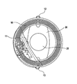
- FIG. 1 is a schematic view of a sensor module according to an embodiment of the invention.
- a sensor module 10 comprises one or more folding axes A 1 , A 2 along which the sensor module can be folded up.
- the folding axes A 1 , A 2 are parallel to a tangent T of the sensor module 10 .
- the sensor module 10 is integrated onto a foldable carrier SR and further comprises a coil SP integrated into the foldable carrier SR, which for example is formed in a planar manner in a flat surface in the form of a plurality of coil windings which are positioned side by side.
- the electronics of the sensor module 10 is integrated for example into switching means E 1 , E 2 which comprise flexible strip conductors 14 , 15 , 16 , 18 and additional components.
- the electronics can be integrated into a single electronics carrier R 1 .
- the sensor module 10 is coated for example with parylene or another inert polymer coating material.
- FIG. 2 is a schematic view of an implant device before it is guided through an operation opening OP according to a further embodiment of the invention.
- An implant device 5 comprises a sensor module 10 and an implant module 20 .
- the implant module 20 comprises one or more second fastening elements 21 , 22 , 23 .
- the fastening elements 21 , 22 , 23 are formed to receive threads F 1 -F 4 .
- the fastening elements 21 , 22 , 23 are formed as eyelets or as another fastening element from a ring made of a biocompatible plastics material or metal.
- the implant device 5 can be unfolded after being pushed through the operation opening OP.
- the implant device 5 can thus be unfolded again in its final position inside the body by a tensile force applied via the threads F 1 -F 4 .
- the implant module is for example held in place using tweezers and at the same time a tensile force is applied to the threads F 1 and/or F 4 .
- the implant module 20 is coated for example with parylene or another inert polymer coating material.
- the implant module 20 is formed as, for example, an intraocular lens or as another artificial lens which is to be implanted into the eye, and said module comprises a lens 25 .
- the coil SP and the associated carrier SR of the sensor module 10 of the implant device 5 are arranged concentrically with the lens 25 of the implant module 20 in this case.
- FIG. 3 is a schematic view of an implant device after it is guided through an operation opening according to a further embodiment of the invention.
- the implant device 5 comprises the sensor module 10 and the implant module 20 .
- the sensor module 10 comprises one or more first fastening means 11 , 12 , 13 , which are designed to fix a connecting module 30 .
- FIGS. 4 to 7 are each schematic views of an implant device according to a further embodiment of the invention.
- FIG. 4 shows an implant device 5 comprising a flexible connecting module 30 .
- the connecting module 30 shown in FIG. 4 is made of a flexible or foldable material, for example. Owing to the use of the flexible connecting module 30 , the implant device 5 has a fold axis A 3 , along which the implant device 5 can be folded up.
- the connecting module 30 shown in FIG. 5 is formed for example as a flexible hinge part.
- the implant device 5 has a fold axis A 3 , along which the implant device 5 can be folded up.
- the implant device 5 shown in FIG. 6 comprises a connecting module 30 , which is formed for example by a thread F 1 and a first fastening means 12 of the sensor module 10 and second fastening means 21 of the implant module 20 .
- the connecting module 30 shown in FIG. 7 is formed for example on one hand by a hinge part 30 a and on the other hand by a thread F 1 and two first fastening means 11 , 12 of the sensor module 10 and two second fastening means 21 , 22 of the implant module 20 .
- FIG. 8 schematically shows a flow diagram of the method for producing an implant device according to a further embodiment of the invention.
- the method for producing an implant device includes the following method steps.
- a sensor module 10 As a first method step, a sensor module 10 , an implant module 20 and a connecting module 30 are provided S 1 .
- the sensor module 10 , the implant module 20 and the connecting module 30 are assembled S 2 to form the implant device 5 , the threads F 1 -F 4 , for example, being pulled through the first fastening means 11 - 13 , formed as eyelets, or through the second fastening means 21 - 23 , formed as eyelets, of the sensor module 10 and of the implant module 20 respectively.
- the assembled implant device 5 is folded S 3 along a fold axis A 3 of the implant device 5 for folding up the implant device 5 .
Landscapes
- Health & Medical Sciences (AREA)
- Ophthalmology & Optometry (AREA)
- Life Sciences & Earth Sciences (AREA)
- Animal Behavior & Ethology (AREA)
- Engineering & Computer Science (AREA)
- Biomedical Technology (AREA)
- Heart & Thoracic Surgery (AREA)
- Veterinary Medicine (AREA)
- Public Health (AREA)
- General Health & Medical Sciences (AREA)
- Vascular Medicine (AREA)
- Cardiology (AREA)
- Oral & Maxillofacial Surgery (AREA)
- Transplantation (AREA)
- Surgery (AREA)
- Molecular Biology (AREA)
- Medical Informatics (AREA)
- Physics & Mathematics (AREA)
- Biophysics (AREA)
- Prostheses (AREA)
Abstract
Description
Claims (17)
Applications Claiming Priority (4)
| Application Number | Priority Date | Filing Date | Title |
|---|---|---|---|
| DE102012200574 | 2012-01-17 | ||
| DE102012200574.9 | 2012-01-17 | ||
| DE201210200574 DE102012200574A1 (en) | 2012-01-17 | 2012-01-17 | Implant device, sensor module, disposable injector with an implant device and method for producing an implant device |
| PCT/EP2013/050334 WO2013107677A1 (en) | 2012-01-17 | 2013-01-10 | Implant device, sensor module, disposable injector with an implant device and method for producing an implant device |
Publications (2)
| Publication Number | Publication Date |
|---|---|
| US20150094806A1 US20150094806A1 (en) | 2015-04-02 |
| US9468522B2 true US9468522B2 (en) | 2016-10-18 |
Family
ID=47563485
Family Applications (1)
| Application Number | Title | Priority Date | Filing Date |
|---|---|---|---|
| US14/372,264 Expired - Fee Related US9468522B2 (en) | 2012-01-17 | 2013-01-10 | Implant device, sensor module, single-use injector and method for producing an implant device |
Country Status (7)
| Country | Link |
|---|---|
| US (1) | US9468522B2 (en) |
| EP (2) | EP3682795A1 (en) |
| JP (1) | JP6276198B2 (en) |
| AU (1) | AU2013211203B2 (en) |
| CA (1) | CA2861463C (en) |
| DE (1) | DE102012200574A1 (en) |
| WO (1) | WO2013107677A1 (en) |
Cited By (3)
| Publication number | Priority date | Publication date | Assignee | Title |
|---|---|---|---|---|
| US9730638B2 (en) | 2013-03-13 | 2017-08-15 | Glaukos Corporation | Intraocular physiological sensor |
| US11363951B2 (en) | 2011-09-13 | 2022-06-21 | Glaukos Corporation | Intraocular physiological sensor |
| US11497399B2 (en) | 2016-05-31 | 2022-11-15 | Qura, Inc. | Implantable intraocular pressure sensors and methods of use |
Families Citing this family (4)
| Publication number | Priority date | Publication date | Assignee | Title |
|---|---|---|---|---|
| DE102014221373A1 (en) | 2014-10-21 | 2016-04-21 | Implandata Ophthalmic Products Gmbh | Combined eye implant |
| BR112018003838A2 (en) | 2015-08-27 | 2018-09-25 | Equinox Inc | modification and identification of eye-related intracorporeal pressure |
| KR20250069675A (en) | 2018-08-09 | 2025-05-19 | 밸런스 오프탈믹스, 인크. | Apparatus and methods to adjust ocular blood flow |
| USD1024816S1 (en) * | 2024-01-25 | 2024-04-30 | Xinhua Tan | Soil meter |
Citations (4)
| Publication number | Priority date | Publication date | Assignee | Title |
|---|---|---|---|---|
| US5005577A (en) | 1988-08-23 | 1991-04-09 | Frenkel Ronald E P | Intraocular lens pressure monitoring device |
| EP0512785A1 (en) | 1991-05-04 | 1992-11-11 | Mohamed Abd El Fattah Hassan Dr. Daif | Intraocular lens implant |
| WO2001021063A1 (en) | 1999-09-24 | 2001-03-29 | Acritec Gesellschaft Für Ophthalmologische Produkte Mbh | Device for measuring physical quantities, especially for measuring pressure in the eye |
| WO2007127305A2 (en) | 2006-04-26 | 2007-11-08 | Eastern Virginia Medical School | Systems and methods for monitoring and controlling internal pressure of an eye or body part |
Family Cites Families (6)
| Publication number | Priority date | Publication date | Assignee | Title |
|---|---|---|---|---|
| DE19637692A1 (en) * | 1996-09-09 | 1998-03-12 | Potsdamer Augenklinik Im Albre | Capsule tensioning ring for stabilising the eye capsule |
| DE19858172A1 (en) * | 1998-12-16 | 2000-06-21 | Campus Micro Technologies Gmbh | Artificial lens implant for measuring eye internal pressure has telemetric endosystem for continuous pressure monitoring incorporated in peripheral rim of artificial lens |
| US6193656B1 (en) * | 1999-02-08 | 2001-02-27 | Robert E. Jeffries | Intraocular pressure monitoring/measuring apparatus and method |
| US7488345B2 (en) * | 2002-06-07 | 2009-02-10 | Endovascular Technologies, Inc. | Endovascular graft with pressor and attachment methods |
| DE102008040142A1 (en) * | 2008-07-03 | 2010-01-07 | Robert Bosch Gmbh | Capsule clamp with coil for inductive coupling to an external electromagnetic field |
| WO2012137067A2 (en) * | 2011-04-07 | 2012-10-11 | Oculox Technology | Intraocular pressure monitoring device and methods |
-
2012
- 2012-01-17 DE DE201210200574 patent/DE102012200574A1/en not_active Withdrawn
-
2013
- 2013-01-10 EP EP19211859.4A patent/EP3682795A1/en not_active Withdrawn
- 2013-01-10 JP JP2014552584A patent/JP6276198B2/en not_active Expired - Fee Related
- 2013-01-10 EP EP13700542.7A patent/EP2804562A1/en not_active Withdrawn
- 2013-01-10 US US14/372,264 patent/US9468522B2/en not_active Expired - Fee Related
- 2013-01-10 WO PCT/EP2013/050334 patent/WO2013107677A1/en not_active Ceased
- 2013-01-10 CA CA2861463A patent/CA2861463C/en not_active Expired - Fee Related
- 2013-01-10 AU AU2013211203A patent/AU2013211203B2/en not_active Ceased
Patent Citations (4)
| Publication number | Priority date | Publication date | Assignee | Title |
|---|---|---|---|---|
| US5005577A (en) | 1988-08-23 | 1991-04-09 | Frenkel Ronald E P | Intraocular lens pressure monitoring device |
| EP0512785A1 (en) | 1991-05-04 | 1992-11-11 | Mohamed Abd El Fattah Hassan Dr. Daif | Intraocular lens implant |
| WO2001021063A1 (en) | 1999-09-24 | 2001-03-29 | Acritec Gesellschaft Für Ophthalmologische Produkte Mbh | Device for measuring physical quantities, especially for measuring pressure in the eye |
| WO2007127305A2 (en) | 2006-04-26 | 2007-11-08 | Eastern Virginia Medical School | Systems and methods for monitoring and controlling internal pressure of an eye or body part |
Non-Patent Citations (1)
| Title |
|---|
| Eggers, T., et al., "Wireless Eye Pressure Monitoring System Integrated into Intra-Ocular Lens", Proc. Micro. Tec. VDE World Microtech. Congress, Sep. 25, 2000, pp. 255-258. |
Cited By (4)
| Publication number | Priority date | Publication date | Assignee | Title |
|---|---|---|---|---|
| US11363951B2 (en) | 2011-09-13 | 2022-06-21 | Glaukos Corporation | Intraocular physiological sensor |
| US9730638B2 (en) | 2013-03-13 | 2017-08-15 | Glaukos Corporation | Intraocular physiological sensor |
| US10849558B2 (en) | 2013-03-13 | 2020-12-01 | Glaukos Corporation | Intraocular physiological sensor |
| US11497399B2 (en) | 2016-05-31 | 2022-11-15 | Qura, Inc. | Implantable intraocular pressure sensors and methods of use |
Also Published As
| Publication number | Publication date |
|---|---|
| CA2861463A1 (en) | 2013-07-25 |
| WO2013107677A1 (en) | 2013-07-25 |
| EP2804562A1 (en) | 2014-11-26 |
| AU2013211203B2 (en) | 2017-10-26 |
| CA2861463C (en) | 2018-08-21 |
| AU2013211203A1 (en) | 2014-08-14 |
| US20150094806A1 (en) | 2015-04-02 |
| JP6276198B2 (en) | 2018-02-07 |
| DE102012200574A1 (en) | 2013-07-18 |
| JP2015503981A (en) | 2015-02-05 |
| EP3682795A1 (en) | 2020-07-22 |
Similar Documents
| Publication | Publication Date | Title |
|---|---|---|
| US9468522B2 (en) | Implant device, sensor module, single-use injector and method for producing an implant device | |
| US11998444B2 (en) | Intraocular lens having input and output electronics | |
| US20210259826A1 (en) | Accommodating intraocular lens assemblies and accommodation measurement implant | |
| JP6821736B2 (en) | Intraocular lens assembly | |
| CN102083357B (en) | Capsule clamp ring with coil for inductive coupling to an external electromagnetic field | |
| US20090027661A1 (en) | Systems and Methods for Testing Intraocular Lenses | |
| EP3492041A1 (en) | Accommodating intraocular lens | |
| JP2012505712A (en) | Adjustable intraocular lens | |
| US9016860B2 (en) | Fluidic adaptive optic fundus camera | |
| CN102647959A (en) | Intraocular lens system | |
| CN111093563A (en) | Multi-component electrowetting intraocular lens for in situ assembly | |
| KR20220151230A (en) | Intraocular pseudophakic contact lenses and related systems and methods | |
| WO2012157623A1 (en) | Intraocular lens | |
| KR101718074B1 (en) | Intraocular lens supporter | |
| CN100457061C (en) | Adjustable artificial crystal based on micro-opto- electro-mechanical system | |
| Moura et al. | Mechanically adjustable lenses |
Legal Events
| Date | Code | Title | Description |
|---|---|---|---|
| AS | Assignment |
Owner name: IMPLANDATA OPHTHALMIC PRODUCTS GMBH, GERMANY Free format text: ASSIGNMENT OF ASSIGNORS INTEREST;ASSIGNOR:SCHOLTEN, DICK;REEL/FRAME:033312/0433 Effective date: 20140714 |
|
| STCF | Information on status: patent grant |
Free format text: PATENTED CASE |
|
| FEPP | Fee payment procedure |
Free format text: MAINTENANCE FEE REMINDER MAILED (ORIGINAL EVENT CODE: REM.); ENTITY STATUS OF PATENT OWNER: SMALL ENTITY |
|
| FEPP | Fee payment procedure |
Free format text: SURCHARGE FOR LATE PAYMENT, SMALL ENTITY (ORIGINAL EVENT CODE: M2554); ENTITY STATUS OF PATENT OWNER: SMALL ENTITY |
|
| MAFP | Maintenance fee payment |
Free format text: PAYMENT OF MAINTENANCE FEE, 4TH YR, SMALL ENTITY (ORIGINAL EVENT CODE: M2551); ENTITY STATUS OF PATENT OWNER: SMALL ENTITY Year of fee payment: 4 |
|
| FEPP | Fee payment procedure |
Free format text: MAINTENANCE FEE REMINDER MAILED (ORIGINAL EVENT CODE: REM.); ENTITY STATUS OF PATENT OWNER: SMALL ENTITY |
|
| LAPS | Lapse for failure to pay maintenance fees |
Free format text: PATENT EXPIRED FOR FAILURE TO PAY MAINTENANCE FEES (ORIGINAL EVENT CODE: EXP.); ENTITY STATUS OF PATENT OWNER: SMALL ENTITY |
|
| STCH | Information on status: patent discontinuation |
Free format text: PATENT EXPIRED DUE TO NONPAYMENT OF MAINTENANCE FEES UNDER 37 CFR 1.362 |
|
| FP | Lapsed due to failure to pay maintenance fee |
Effective date: 20241018 |