US9468417B1 - Stenotic lesion characterization - Google Patents
Stenotic lesion characterization Download PDFInfo
- Publication number
- US9468417B1 US9468417B1 US13/525,159 US201213525159A US9468417B1 US 9468417 B1 US9468417 B1 US 9468417B1 US 201213525159 A US201213525159 A US 201213525159A US 9468417 B1 US9468417 B1 US 9468417B1
- Authority
- US
- United States
- Prior art keywords
- blood vessel
- physical dimension
- blood flow
- flow rate
- stenotic lesion
- Prior art date
- Legal status (The legal status is an assumption and is not a legal conclusion. Google has not performed a legal analysis and makes no representation as to the accuracy of the status listed.)
- Active, expires
Links
- 230000003902 lesion Effects 0.000 title claims abstract description 221
- 230000002966 stenotic effect Effects 0.000 title claims abstract description 171
- 238000012512 characterization method Methods 0.000 title description 3
- 238000005259 measurement Methods 0.000 claims abstract description 249
- 210000004204 blood vessel Anatomy 0.000 claims abstract description 243
- 230000017531 blood circulation Effects 0.000 claims abstract description 205
- 230000000544 hyperemic effect Effects 0.000 claims abstract description 22
- 239000003071 vasodilator agent Substances 0.000 claims abstract description 8
- 230000000144 pharmacologic effect Effects 0.000 claims abstract description 5
- 230000008859 change Effects 0.000 claims description 34
- 238000000034 method Methods 0.000 claims description 33
- 208000028867 ischemia Diseases 0.000 claims description 28
- 230000000747 cardiac effect Effects 0.000 claims description 27
- 230000001939 inductive effect Effects 0.000 claims description 23
- 230000003287 optical effect Effects 0.000 claims description 11
- 230000002792 vascular Effects 0.000 claims description 4
- 210000004351 coronary vessel Anatomy 0.000 claims description 3
- 230000010339 dilation Effects 0.000 claims 40
- 239000003814 drug Substances 0.000 description 10
- 229940079593 drug Drugs 0.000 description 10
- 239000008280 blood Substances 0.000 description 9
- 210000004369 blood Anatomy 0.000 description 9
- 230000004962 physiological condition Effects 0.000 description 9
- 230000004044 response Effects 0.000 description 9
- 230000000302 ischemic effect Effects 0.000 description 7
- 230000001965 increasing effect Effects 0.000 description 6
- 238000011282 treatment Methods 0.000 description 6
- 230000000304 vasodilatating effect Effects 0.000 description 6
- 238000010586 diagram Methods 0.000 description 5
- 239000012530 fluid Substances 0.000 description 5
- 238000002608 intravascular ultrasound Methods 0.000 description 5
- 210000001519 tissue Anatomy 0.000 description 5
- OIRDTQYFTABQOQ-KQYNXXCUSA-N adenosine Chemical compound C1=NC=2C(N)=NC=NC=2N1[C@@H]1O[C@H](CO)[C@@H](O)[C@H]1O OIRDTQYFTABQOQ-KQYNXXCUSA-N 0.000 description 4
- 238000002399 angioplasty Methods 0.000 description 4
- 239000003795 chemical substances by application Substances 0.000 description 4
- 230000009471 action Effects 0.000 description 3
- 230000036770 blood supply Effects 0.000 description 3
- 238000004891 communication Methods 0.000 description 3
- 239000013078 crystal Substances 0.000 description 3
- 230000006870 function Effects 0.000 description 3
- 208000031225 myocardial ischemia Diseases 0.000 description 3
- 238000012545 processing Methods 0.000 description 3
- 239000002126 C01EB10 - Adenosine Substances 0.000 description 2
- 206010020565 Hyperaemia Diseases 0.000 description 2
- 229960005305 adenosine Drugs 0.000 description 2
- 238000013459 approach Methods 0.000 description 2
- 210000001367 artery Anatomy 0.000 description 2
- 230000004323 axial length Effects 0.000 description 2
- 230000008901 benefit Effects 0.000 description 2
- HVYWMOMLDIMFJA-DPAQBDIFSA-N cholesterol Chemical compound C1C=C2C[C@@H](O)CC[C@]2(C)[C@@H]2[C@@H]1[C@@H]1CC[C@H]([C@H](C)CCCC(C)C)[C@@]1(C)CC2 HVYWMOMLDIMFJA-DPAQBDIFSA-N 0.000 description 2
- 230000000052 comparative effect Effects 0.000 description 2
- 230000004069 differentiation Effects 0.000 description 2
- 238000002651 drug therapy Methods 0.000 description 2
- 238000013152 interventional procedure Methods 0.000 description 2
- 239000000463 material Substances 0.000 description 2
- 238000012014 optical coherence tomography Methods 0.000 description 2
- 238000000053 physical method Methods 0.000 description 2
- 238000002604 ultrasonography Methods 0.000 description 2
- 230000024883 vasodilation Effects 0.000 description 2
- 238000009825 accumulation Methods 0.000 description 1
- 230000003213 activating effect Effects 0.000 description 1
- 230000004913 activation Effects 0.000 description 1
- 238000011256 aggressive treatment Methods 0.000 description 1
- 210000000709 aorta Anatomy 0.000 description 1
- 230000036772 blood pressure Effects 0.000 description 1
- 230000002308 calcification Effects 0.000 description 1
- 235000012000 cholesterol Nutrition 0.000 description 1
- 238000010276 construction Methods 0.000 description 1
- 230000009849 deactivation Effects 0.000 description 1
- 201000010099 disease Diseases 0.000 description 1
- 208000037265 diseases, disorders, signs and symptoms Diseases 0.000 description 1
- 235000019800 disodium phosphate Nutrition 0.000 description 1
- 230000000694 effects Effects 0.000 description 1
- 238000011156 evaluation Methods 0.000 description 1
- 238000004519 manufacturing process Methods 0.000 description 1
- 238000012544 monitoring process Methods 0.000 description 1
- 210000004165 myocardium Anatomy 0.000 description 1
- 230000037361 pathway Effects 0.000 description 1
- 230000035479 physiological effects, processes and functions Effects 0.000 description 1
- 238000003825 pressing Methods 0.000 description 1
- 230000008569 process Effects 0.000 description 1
- 230000001902 propagating effect Effects 0.000 description 1
- 238000005086 pumping Methods 0.000 description 1
- 238000003860 storage Methods 0.000 description 1
- 238000012360 testing method Methods 0.000 description 1
- 230000001052 transient effect Effects 0.000 description 1
- 238000013519 translation Methods 0.000 description 1
Images


Classifications
-
- A—HUMAN NECESSITIES
- A61—MEDICAL OR VETERINARY SCIENCE; HYGIENE
- A61B—DIAGNOSIS; SURGERY; IDENTIFICATION
- A61B8/00—Diagnosis using ultrasonic, sonic or infrasonic waves
- A61B8/12—Diagnosis using ultrasonic, sonic or infrasonic waves in body cavities or body tracts, e.g. by using catheters
-
- A—HUMAN NECESSITIES
- A61—MEDICAL OR VETERINARY SCIENCE; HYGIENE
- A61B—DIAGNOSIS; SURGERY; IDENTIFICATION
- A61B5/00—Measuring for diagnostic purposes; Identification of persons
- A61B5/02—Detecting, measuring or recording pulse, heart rate, blood pressure or blood flow; Combined pulse/heart-rate/blood pressure determination; Evaluating a cardiovascular condition not otherwise provided for, e.g. using combinations of techniques provided for in this group with electrocardiography or electroauscultation; Heart catheters for measuring blood pressure
- A61B5/02007—Evaluating blood vessel condition, e.g. elasticity, compliance
-
- A—HUMAN NECESSITIES
- A61—MEDICAL OR VETERINARY SCIENCE; HYGIENE
- A61B—DIAGNOSIS; SURGERY; IDENTIFICATION
- A61B5/00—Measuring for diagnostic purposes; Identification of persons
- A61B5/103—Detecting, measuring or recording devices for testing the shape, pattern, colour, size or movement of the body or parts thereof, for diagnostic purposes
- A61B5/107—Measuring physical dimensions, e.g. size of the entire body or parts thereof
-
- A—HUMAN NECESSITIES
- A61—MEDICAL OR VETERINARY SCIENCE; HYGIENE
- A61B—DIAGNOSIS; SURGERY; IDENTIFICATION
- A61B5/00—Measuring for diagnostic purposes; Identification of persons
- A61B5/68—Arrangements of detecting, measuring or recording means, e.g. sensors, in relation to patient
- A61B5/6846—Arrangements of detecting, measuring or recording means, e.g. sensors, in relation to patient specially adapted to be brought in contact with an internal body part, i.e. invasive
- A61B5/6867—Arrangements of detecting, measuring or recording means, e.g. sensors, in relation to patient specially adapted to be brought in contact with an internal body part, i.e. invasive specially adapted to be attached or implanted in a specific body part
- A61B5/6876—Blood vessel
-
- A—HUMAN NECESSITIES
- A61—MEDICAL OR VETERINARY SCIENCE; HYGIENE
- A61B—DIAGNOSIS; SURGERY; IDENTIFICATION
- A61B5/00—Measuring for diagnostic purposes; Identification of persons
- A61B5/0059—Measuring for diagnostic purposes; Identification of persons using light, e.g. diagnosis by transillumination, diascopy, fluorescence
- A61B5/0062—Arrangements for scanning
- A61B5/0066—Optical coherence imaging
-
- A—HUMAN NECESSITIES
- A61—MEDICAL OR VETERINARY SCIENCE; HYGIENE
- A61B—DIAGNOSIS; SURGERY; IDENTIFICATION
- A61B5/00—Measuring for diagnostic purposes; Identification of persons
- A61B5/0059—Measuring for diagnostic purposes; Identification of persons using light, e.g. diagnosis by transillumination, diascopy, fluorescence
- A61B5/0082—Measuring for diagnostic purposes; Identification of persons using light, e.g. diagnosis by transillumination, diascopy, fluorescence adapted for particular medical purposes
- A61B5/0084—Measuring for diagnostic purposes; Identification of persons using light, e.g. diagnosis by transillumination, diascopy, fluorescence adapted for particular medical purposes for introduction into the body, e.g. by catheters
-
- A—HUMAN NECESSITIES
- A61—MEDICAL OR VETERINARY SCIENCE; HYGIENE
- A61B—DIAGNOSIS; SURGERY; IDENTIFICATION
- A61B5/00—Measuring for diagnostic purposes; Identification of persons
- A61B5/68—Arrangements of detecting, measuring or recording means, e.g. sensors, in relation to patient
- A61B5/6846—Arrangements of detecting, measuring or recording means, e.g. sensors, in relation to patient specially adapted to be brought in contact with an internal body part, i.e. invasive
- A61B5/6847—Arrangements of detecting, measuring or recording means, e.g. sensors, in relation to patient specially adapted to be brought in contact with an internal body part, i.e. invasive mounted on an invasive device
- A61B5/6852—Catheters
-
- A—HUMAN NECESSITIES
- A61—MEDICAL OR VETERINARY SCIENCE; HYGIENE
- A61B—DIAGNOSIS; SURGERY; IDENTIFICATION
- A61B8/00—Diagnosis using ultrasonic, sonic or infrasonic waves
- A61B8/08—Detecting organic movements or changes, e.g. tumours, cysts, swellings
- A61B8/0883—Detecting organic movements or changes, e.g. tumours, cysts, swellings for diagnosis of the heart
-
- A—HUMAN NECESSITIES
- A61—MEDICAL OR VETERINARY SCIENCE; HYGIENE
- A61B—DIAGNOSIS; SURGERY; IDENTIFICATION
- A61B8/00—Diagnosis using ultrasonic, sonic or infrasonic waves
- A61B8/08—Detecting organic movements or changes, e.g. tumours, cysts, swellings
- A61B8/0891—Detecting organic movements or changes, e.g. tumours, cysts, swellings for diagnosis of blood vessels
-
- A—HUMAN NECESSITIES
- A61—MEDICAL OR VETERINARY SCIENCE; HYGIENE
- A61B—DIAGNOSIS; SURGERY; IDENTIFICATION
- A61B8/00—Diagnosis using ultrasonic, sonic or infrasonic waves
- A61B8/52—Devices using data or image processing specially adapted for diagnosis using ultrasonic, sonic or infrasonic waves
- A61B8/5215—Devices using data or image processing specially adapted for diagnosis using ultrasonic, sonic or infrasonic waves involving processing of medical diagnostic data
- A61B8/5223—Devices using data or image processing specially adapted for diagnosis using ultrasonic, sonic or infrasonic waves involving processing of medical diagnostic data for extracting a diagnostic or physiological parameter from medical diagnostic data
Definitions
- This disclosure relates to stenotic lesions and, more particularly, to intravascular measurement devices and techniques for characterizing stenotic lesions.
- Assessing the severity of a stenotic lesion is an important part of recommending a treatment option.
- a treatment option such as a stent, angioplasty, etc. are often recommended to inhibit or roll back growth of a stenotic lesion. That said, treatment options can result in their own negative consequences.
- Angiograms are common methods of assessing the severity of a stenotic lesion, but, in many cases, there is a desire for additional means of gathering information to more fully characterize the stenotic lesion.
- this disclosure is directed to techniques for evaluating and/or characterizing a stenotic lesion to determine whether or not the lesion is inducing ischemia. If a lesion is determined to be inducing ischemia, a healthcare provider may take a comparatively aggressive treatment approach, such as performing angioplasty or inserting a stent to treat the lesion. On the other hand, if the lesion is not determined to be inducing ischemia, the healthcare provider may adopt a more passive treatment approach, such as drug therapy and future monitoring of the lesion.
- an intravascular measurement device is inserted into a region of a blood vessel that has the lesion.
- the intravascular measurement device may be used to measure a physical dimension of the blood vessel at one or more locations in the blood vessel.
- the intravascular measurement device may be used to measure a physical dimension of the blood vessel at a location distal to the stenotic lesion, a location proximal to the stenotic lesion, and/or a location in the region of the stenotic lesion where the blood vessel defines a minimal lumen diameter (e.g., a location where the lesion causes the maximum narrowing of the blood vessel lumen).
- the intravascular measurement device may measure the physical dimension of the blood vessel at a first condition, such as when a first blood flow rate is passing through the blood vessel, and again at a second condition, such as when a second blood flow rate greater than the first blood flow rate is passing through the blood vessel.
- the first blood flow rate may be a natural blood flow rate through the patient (e.g., without the influence of external agents that may influence the blood flow rate) whereas the second blood flow rate may be an artificially increased blood flow rate (e.g., a maximal hyperemic blood flow rate).
- a stenotic lesion that is not ischemia inducing may exhibit a change in physical dimension between the first condition (e.g., blood flow rate) and the second condition that is different than a change in physical dimension exhibited by an ischemia-inducing lesion.
- the intravascular measurement device may be used to determine whether or not a stenotic lesion is ischemia inducing.
- a method in one example, includes receiving a first measurement signal from an intravascular measurement device, the first measurement signal being indicative of a physical dimension of a blood vessel having a stenotic lesion during a first blood flow rate.
- the method includes receiving a second measurement signal from the intravascular measurement device, the second measurement signal being indicative of the physical dimension of the blood vessel having the stenotic lesion during a second blood flow that is greater than the first blood flow rate.
- the method further includes determining, with a processor, a value representative of a change in the physical dimension of the blood vessel between the first blood flow rate and the second blood flow rate based on the first measurement signal and the second measurement signal.
- a system in another example, includes an intravascular measurement device, a catheter configured to deliver the intravascular measurement device to a desired location in a body of a patient, and a processor.
- the processor is configured to receive a first measurement signal from the intravascular measurement device, the first measurement signal being indicative of a physical dimension of a blood vessel having a stenotic lesion during a first blood flow rate, receive a second measurement signal from the intravascular measurement device, the second measurement signal being indicative of the physical dimension of the blood vessel having the stenotic lesion during a second blood flow rate that is greater than the first blood flow rate, and determine a value representative of a change in the physical dimension of the blood vessel between the first blood flow rate and the second blood flow rate based on the first measurement signal and the second measurement signal.
- a non-transitory computer-readable medium includes instructions for causing a programmable processor to receive a first measurement signal from an intravascular measurement device and receive a second measurement signal from the intravascular measurement device.
- the first measurement signal is indicative of a physical dimension of a blood vessel having a stenotic lesion during a first blood flow rate
- the second measurement signal is indicative of the physical dimension of the blood vessel having the stenotic lesion during a second blood flow that is greater than the first blood flow rate.
- the computer-readable medium also includes instructions for causing a programmable processor to determine a value representative of a change in the physical dimension of the blood vessel between the first blood flow rate and the second blood flow rate based on the first measurement signal and the second measurement signal.
- a method in another example, includes inserting an intravascular measurement device into a body of a patient and measuring via the intravascular measurement device a physical dimension of a blood vessel having a stenotic lesion during a non-hyperemic blood flow rate. The method further includes introducing a pharmacologic vasodilator drug into the body of the patient so as to cause the patient to exhibit hyperemic blood flow rates and measuring via the intravascular measurement device the physical dimension of a blood vessel having the stenotic lesion during a hyperemic blood flow rate.
- FIG. 1 is a conceptual diagram illustrating an example system comprising an intravascular measurement device that may be used to evaluate a stenotic lesion in a patient.
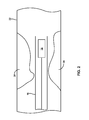
- FIG. 2 is cross-sectional conceptual diagram illustrating the intravascular measurement device of FIG. 1 positioned in an example blood vessel.
- FIG. 3 is a functional block diagram illustrating an example configuration of the system of FIG. 1 .
- Ischemic heart disease which may also be referred to as myocardial ischemia, is a disease characterized by reduced blood supply to the heart muscle. Ischemic heart disease can occur due when a wall of a coronary artery thickens, e.g., due to the accumulation of fatty materials such as cholesterol. Regions of an artery or other blood vessel that are abnormally narrowed, for example due to accumulated fatty deposits, are typically referred to as stenotic lesions. Although stenotic lesions narrow the flow path through a blood vessel, thereby restricting fluid movement through the blood vessel, some stenotic lesions have minimal impact on the flow of blood through the vessel.
- ischemia-inducing lesions are typically treated through more aggressive interventional procedures, such as angioplasty or stent placement, to help remove the blockage and restore blood supply to the tissue. Being able to accurately evaluate and characterize a lesion in a patient may be useful to ensure that the patient receives the appropriate treatment corresponding to the severity of the lesion.
- a lesion characterization system includes an intravascular measurement device that can be inserted through the vascular structure of a patient to a location where there is a stenotic lesion.
- the intravascular measurement device may be an intravascular ultrasound device (IVUS), an intravascular optical device such an intracoronary optical coherence tomography device, or yet a different type of intravascular measurement device.
- IVUS intravascular ultrasound device
- the intravascular measurement device can be used to measure a physical dimension of the blood vessel within the stenotic lesion.
- the intravascular measurement device may be used to measure a diameter, a cross-sectional area, and/or a volume of either the stenotic lesion itself or a region proximate the stenotic lesion.
- the intravascular measurement device is used to measure physical dimensions of the blood vessel at multiple different locations relative to the stenotic lesion, such as a physical dimension of the blood vessel at a location distal to the stenotic lesion and a physical dimension of the blood vessel at a location proximal to the stenotic lesion.
- the intravascular measurement device may measure a blood vessel within a stenotic lesion at a specific location or locations of under a first set of physiological conditions and then re-measure the blood vessel at the same location or locations under a second set of physiological conditions that are different than the first set of physiological conditions.
- the change in physical dimensions of the blood vessel caused by the changing physiological conditions may indicate whether or not the stenotic lesion being evaluated is likely to induce ischemia.
- the physical dimensions of the blood vessel being measured may change a certain amount if the stenotic lesion is an ischemia-inducing lesion while the physical dimensions of the blood vessel may change a different amount if the stenotic lesion is nonischemic.
- the determination of whether the stenotic lesion is ischemic or nonischemic may dictate how the stenotic lesion is subsequently treated.
- FIG. 1 is a conceptual diagram illustrating an example system 10 that may be used to evaluate and/or characterize a stenotic lesion in the body of patient 14 .
- System 10 includes a catheter 16 , an intravascular measurement device 18 , and a console 20 .
- Intravascular measurement device 18 can be inserted into the body of patient 14 and used to measure various anatomical characteristics within patient 14 .
- intravascular measurement device 18 can be used to measure a physical dimension of a blood vessel of patient 14 .
- intravascular measurement device 18 is shown positioned within a coronary artery of patient 14 and connected via catheter 16 to console 20 , which is positioned outside of the body of patient 14 .
- intravascular measurement device 18 can be positioned in other arteries, blood vessels, or body lumens that contain a lesion.
- Console 20 may house various operating components of system 10 that control the operation of intravascular measurement device 18 , send signals to or receive signals from the intravascular measurement device, store data generated by or used with the intravascular measurement device, or the like.
- console 20 also includes a user interface that allows a clinician to interact with intravascular measurement device 18 and/or display information generated by the intravascular measurement device.
- a clinician may insert intravascular measurement device 18 into a blood vessel of patient 14 that has a stenotic lesion.
- the clinician may use the intravascular measurement device to make at least two measurements of the blood vessel under at least two different conditions. For example, the clinician may use intravascular measurement device 18 to make a first measurement at a specific location in the blood vessel under a first set of conditions and then use the intravascular measurement device to make a second measurement at the same specific location in the blood vessel under a second set of conditions.
- the first set of conditions is a first blood flow rate passing through the blood vessel and the second set of conditions is a second blood flow rate passing through the blood vessel that is higher than the first blood flow rate.
- the first blood flow rate may be a normal (e.g., non-hyperemic) blood flow rate and the second blood flow rate may be a hyperemic blood flow rate.
- a clinician may induce hyperemia in patient 14 , e.g., by administering a vasodilation agent, to cause the change in blood flow rate.
- System 10 may compare a blood vessel measurement determined by intravascular measurement device 18 under the first set of conditions to a blood vessel measurement determined by the intravascular measurement device under the second set of conditions. System 10 may determine whether the stenotic lesion within the blood vessel is ischemic or nonischemic based on the comparison.
- intravascular measurement device 18 of system 10 may be positioned within a lumen of the body of patient 14 and used to measure the lumen into which the device is positioned.
- intravascular measurement device 18 may measure a physical dimension of the lumen into which the device is positioned.
- intravascular measurement device 18 may emit energy into the body lumen into which the device is positioned. Different objects within the body (e.g., different tissues) may absorb, transmit, and reflect different amounts of the emitted energy.
- intravascular measurement device 18 may receive emitted energy that is reflected back from the different bodily objects and determine based on the received energy (e.g., the magnitude and/or timing of the received energy) a physical dimension of the bodily lumen into which the device is inserted.
- intravascular measurement device 18 emits energy radially 360 degrees around the device and receives reflected energy from bodily structure positioned around the circumference of the device.
- intravascular measurement device 18 may emit energy radially in one direction while being rotated at least one revolution so as to emit the energy 360 degrees around the device.
- intravascular measurement device 18 may include multiple energy emitters positioned so as to direct energy in a plurality of radial directions around the device. The multiple energy emitters may emit energy simultaneously or the multiple energy emitters may emit energy at different times. In some examples, each of the multiple energy emitters emits energy at a different time, effectively providing a rotating energy beam around the perimeter of the device that is created by controlling the electrical activation and deactivation of different energy emitters.
- the device may determine physical dimensions of the lumen into which the device is inserted in different directions rather than only a single direction. This information can be used to determine a diameter of the lumen into which intravascular measurement device 18 is positioned, a cross-sectional area of the lumen, or other physical dimensions. For instance, when intravascular measurement device 18 is translated axially along a length of the lumen while emitting energy and receiving reflected energy, the device may determine a volume of the lumen (or a portion of the lumen) based on the length of axial translation and determined cross-sectional area of the lumen.
- Intravascular measurement device 18 can be implemented using any suitable device.
- intravascular measurement device 18 is an intravascular ultrasound device (IVUS).
- An intravascular ultrasound device can emit acoustical energy at an ultrasonic frequency or frequencies and receive back a reflected portion of the emitted ultrasonic pressure wave.
- intravascular measurement device 18 is an intravascular optical measurement device.
- An intravascular optical measurement device can emit optical energy (e.g., light) and receive back a reflected portion of the optical energy.
- An optical coherence tomography device is an example of an intravascular optical measurement device.
- intravascular measurement device 18 may or may not be configured to image the blood vessel of patient 14 into which the device is inserted.
- Catheter 16 connects intravascular measurement device 18 to console 20 .
- Catheter 16 may define a lumen that allows signals to communicate from console 20 to intravascular measurement device 18 and also allows signals to communicate from intravascular measurement device 18 to console 20 , e.g., via one or more communication lines (e.g., electrical, optical, and/or fluid communication lines) extending along the length of the catheter.
- Catheter 16 can comprise a unitary catheter or a plurality of catheter segments connected together to form an overall catheter length. In the example of FIG. 1 , catheter 16 traverses from console 20 to a target measurement site within patient 14 .
- catheter 16 may vary depending, e.g., on the type of intravascular measurement device 18 used in system 10 .
- catheter 16 may be a mechanical rotating catheter or an array catheter. With a mechanically rotating catheter, the catheter can mechanically rotate an ultrasonic emitter and/or receiver of intravascular measurement device 18 within a catheter sheath that is transparent to the frequency of ultrasonic energy being emitted and/or received. As the catheter rotates the ultrasonic emitter and/or receiver, an ultrasonic beam sweeps across a region of interest generating data representative of the physical dimensions of the lumen into which the catheter is inserted.
- a plurality of ultrasonic emitters and/or receivers can be positioned (e.g., ringed) about the perimeter of the catheter so as to generate data representative of the physical dimensions of the lumen into which the catheter is inserted without physically rotating an ultrasonic emitter and/or receiver.
- a clinician may catheterize the patient and deliver intravascular measurement device 18 via catheter 16 to a target measurement location.
- the clinician may first deliver a guidewire to an area of interest in patient 14 (e.g., an area that includes the stenotic lesion) and then deliver catheter 16 over the guidewire.
- the clinician may use system 10 (e.g., intravascular measurement device 18 of system 10 ) to measure various physical dimensions within the region of the patient that includes the stenotic lesion.
- FIG. 2 is a cross-sectional schematic showing an example portion of a blood vessel 22 having a stenotic lesion 24 .
- Intravascular measurement device 18 is inserted into blood vessel 22 to measure a physical dimension of the blood vessel in a region proximate stenotic lesion 24 .
- intravascular measurement device 18 is inserted into blood vessel 22 so as to measure a physical dimension of the blood vessel a location distal to stenotic lesion 24 .
- a location may be distal to stenotic lesion 24 in that intravascular measurement device 18 may need to traverse past the stenotic lesion in order to measure a physical dimension of the location.
- intravascular measurement device 18 is inserted into blood vessel 22 so as to measure a physical dimension of the blood vessel a location proximal to stenotic lesion 24 .
- a location may be proximal to stenotic lesion 24 in that intravascular measurement device 18 may measure a physical dimension of the location without traversing past the stenotic lesion. That is, as intravascular measurement device 18 is advanced into the body of patient 14 ( FIG. 1 ), the intravascular measurement device may encounter the region proximal to stenotic lesion 24 prior to encountering the stenotic lesion itself as the device is advanced axially forward in the body.
- measuring a physical dimension of blood vessel 22 in the region proximate stenotic lesion 24 may be useful for characterizing the lesion and, in some examples, determining whether or not the lesion is ischemic.
- a physical dimension of blood vessel 22 may indicate to a clinician the amount of constriction (e.g., narrowing) of the blood vessel caused by stenotic lesion 24 . Accordingly, with knowledge of the physical dimension of blood vessel 22 , a clinician can assess how much impact stenotic lesion has on the physiology of patient 14 ( FIG. 1 ) and determine an appropriate treatment regime.
- intravascular measurement device 18 may be used to make multiple (e.g., at least two) measurements of a physical dimension of blood vessel 22 in a region proximate stenotic lesion 24 , where each measurement is made at the same (or substantially the same) location within patient 14 and each measurement is made under different conditions (e.g. physiological conditions).
- intravascular measurement device 18 may be used to make multiple measurements of a physical dimension of blood vessel 22 in a region proximate stenotic lesion 24 , where each measurement is made at the same (or substantially the same) location within patient 14 and each measurement is made with different blood flow rates passing through the blood vessel being measured.
- intravascular measurement device 18 may measure blood vessel 22 at a specific location in the blood vessel when a first rate of blood is flowing through the vessel and intravascular measurement device 18 may re-measure blood vessel 22 at the same (or substantially the same) specific location in the blood vessel when a second rate of blood is flowing through the vessel.
- the second rate of blood flow may be higher or lower than the first rate of blood flow, depending on the specific application.
- a change in physical dimensions of a blood vessel and/or lesion in response to changing physiological conditions within a patient may be different for an ischemia-inducing lesion than for a lesion that does not induce ischemia.
- the blood vessel 22 when blood vessel 22 is measured in a region proximate stenotic lesion 24 at a first blood flow rate, the blood vessel may be expected to have a certain physical dimension. Increasing the blood flow rate through blood vessel 22 may be expected to increase the physical dimension of the blood vessel because pressure within the blood vessel caused by the increased flow rate may expand the blood vessel outward.
- the amount blood vessel 22 expands in response to increasing blood flow rates may vary depending on how much the walls of the blood vessel have hardened, e.g., due to calcification. For example, in instances in which blood vessel 22 has a lesion that is characterized as ischemia-inducing, the wall of the blood vessel may expand less than instances in which the lesion is characterized as not being ischemia-inducing. In this manner, making multiple measurements of a physical dimension of blood vessel 22 in a region proximate stenotic lesion 24 , where each measurement is made under different conditions (e.g. physiological conditions) may be useful to determine whether or not a lesion is ischemic-inducing.
- conditions e.g. physiological conditions
- intravascular measurement device 18 may be used to make multiple (e.g., at least two) measurements of a physical dimension of blood vessel 22 in at least two different locations within the region proximate stenotic lesion 24 , where each measurement is made under the same (or substantially the same) conditions (e.g. physiological conditions).
- intravascular measurement device 18 may be used to make a measurement of blood vessel 22 at a location distal to stenotic lesion 24 and also at a location proximal to the lesion. Both measurements may be made under the same conditions (e.g., same blood flow rates). Comparison of measurements made under the same conditions at different locations within blood vessel 22 may also be useful for determining whether or not a lesion is ischemic-inducing.
- intravascular measurement device 18 measures blood vessel 22 at one or more locations at a first blood flow rate and then again measured the blood vessel at the same one or more locations at a second blood flow rate that is different (e.g., greater) than the first blood flow rate.
- the first blood flow rate may be a normal (e.g., non-hyperemic) blood flow rate and the second blood flow rate may be a hyperemic blood flow rate.
- the first blood flow rate may be a natural blood flow rate through the patient (e.g., without the influence of external agents that may influence the blood flow rate) and the second blood flow rate may be an artificially increased blood flow rate (e.g., a maximal hyperemic blood flow rate).
- a clinician may vary the blood flow rate of patient 14 by administering a pharmacologic vasodilator drug such as adenosine to the patient.
- a pharmacologic vasodilator drug such as adenosine
- the drug may cause vasodilation, or an opening of the patient's blood vessels. In turn, this may reduce resistance to blood flow through the patient's blood vessel, resulting in an increase in blood flow through the blood vessel.
- a clinician may use intravascular measurement device 18 to determine physical dimensions of blood vessel 22 at one or more locations in a region proximate stenotic lesion 24 prior to administration of a vasodilator drug.
- the clinician may then introduce the vasodilator drug into the patient (e.g., by administering an oral agent or injecting a drug) and wait until the patient exhibits hyperemic blood flow conditions (e.g., maximal hyperemia when blood flow is the greatest).
- hyperemic blood flow conditions e.g., maximal hyperemia when blood flow is the greatest.
- the clinician may use intravascular measurement device 18 to determine the physical dimensions of blood vessel 22 at the one or more locations measured prior to administration of the vasodilator drug.
- vasodilatory drug like adenosine
- the process of administering the drug and waiting for the drug to take effect can add substantial amounts of time to the characterization procedure.
- some patients report discomfort when receiving vasodilatory drugs.
- some care providers may prefer to avoid administering a vasodilatory drug to patients when assessing the severity of a stenotic lesion.
- a clinician may use intravascular measurement device 18 to measure blood vessel 22 at one or more locations without administering a vasodilatory drug. Instead, the clinician (or a device in system 10 in FIG. 1 ) may monitor a parameter indicative of nature blood conduction through patient 14 ( FIG. 1 ) and use intravascular measurement device 18 to measure blood vessel 22 during transient periods when blood flow rates are comparatively low and comparatively high. Blood flow rate variations may occur in the body due to the discontinuous mechanical pumping action of the heart.
- a blood flow rate through blood vessel 22 during a period corresponding to diastole, when the heart is refilling with blood may be lower than a blood flow rate through blood vessel 22 during a period corresponding to systole, when the heart is contracting.
- a physical dimension of blood vessel 22 is measured via intravascular measurement device 18 during a first part of a patient's cardiac cycle (e.g., when blood flow rate is comparatively low) and again during a second part of the cardiac cycle (e.g., when blood flow rate is higher as compared to the first part of the cardiac cycle).
- the second part of the cardiac cycle is a portion of the cardiac cycle in which resistance to fluid flow in the vascular system of patient 14 is minimal.
- Measuring a physical dimension of blood vessel 22 during a specific portion of a cardiac cycle may be a variation of a technique known to those skilled in the art that measures pressure drop across a stenotic lesion without using vasodilatory drugs. This method, called the instant wave-Free Ratio (iFR), relies on a short segment of the coronary waveform in which the downstream resistance to blood flow is relatively stable.
- iFR instant wave-Free Ratio
- intravascular measurement device 18 may measure a physical dimension of blood vessel 22 at one or more locations during a portion of the cardiac cycle where there are no proximally-originating (e.g., from the ventricle and aorta of the heart) or distally-originating (e.g., from the microvascular) pressure waves propagating through blood vessel 22 . This measurement may be indicative of a physical dimension of blood vessel 22 at a comparative high blood flow rate. Intravascular measurement device 18 may measure a physical dimension of blood vessel 22 at the one or more locations during a different portion of the cardiac cycle to generate a measurement indicative of the physical dimension of blood vessel 22 at a comparative low blood flow rate.
- intravascular measurement device 18 can be used to measure a physical dimension of blood vessel 22 at a variety of different locations within the region of stenotic lesion 24 .
- intravascular measurement device 18 may be used to measure a physical dimension of blood vessel 22 at multiple (e.g., two, three, four, or more) locations within the region of stenotic lesion 24 .
- the specific location within blood vessel 22 that a clinician will use intravascular measurement device 18 to measure may vary, e.g., depending on the characteristics of the lesion being examined, the location of the lesion, and other clinically relevant factors.
- intravascular measurement device 18 is inserted into blood vessel 22 to measure a physical dimension of the blood vessel at a location distal to stenotic lesion 24 . If stenotic lesion 24 is well defined with a non-diseased section of blood vessel 22 located distally from the lesion, intravascular measurement device 18 may measure a physical dimension of distally located non-diseased section of blood vessel (e.g., a section of the non-diseased blood vessel closest to the stenotic lesion in the distal direction).
- the clinician may measure blood vessel 22 at a defined location that is distal from where stenotic lesion 24 causes a maximum narrowing of the blood vessel lumen.
- clinician may measure blood vessel 22 at a distal location that ranges from approximately 5 millimeters (mm) to approximately 50 mm (e.g., from approximately 10 mm to approximately 20 mm) from a location where stenotic lesion 24 causes a maximum narrowing of the blood vessel lumen. This measurement may be considered a measurement of blood vessel 22 at a location distal to stenotic lesion 24 .
- intravascular measurement device 18 is inserted into blood vessel 22 to measure a physical dimension of the blood vessel at a location proximal to stenotic lesion 24 . If stenotic lesion 24 is well defined with a non-diseased section of blood vessel 22 located proximally from the lesion, intravascular measurement device 18 may measure a physical dimension of proximally located non-diseased section of blood vessel (e.g., a section of the non-diseased blood vessel closest to the stenotic lesion in the proximal direction).
- the clinician may measure blood vessel 22 at a defined location that is proximal from where stenotic lesion 24 causes a maximum narrowing of the blood vessel lumen.
- clinician may measure blood vessel 22 at a proximal location that ranges from approximately 5 millimeters (mm) to approximately 50 mm (e.g., from approximately 10 mm to approximately 20 mm) from a location where stenotic lesion 24 causes a maximum narrowing of the blood vessel lumen. This measurement may be considered a measurement of blood vessel 22 at a location proximal to stenotic lesion 24 .
- intravascular measurement device 18 is inserted into blood vessel 22 to measure a physical dimension of the blood vessel at a location where stenotic lesion 24 is present.
- the blood vessel is measured where stenotic lesion 24 causes a maximum narrowing of the blood vessel lumen. This position may be representative of the narrowest flow pathway through which blood can pass through blood vessel 22 . It should be appreciated that a clinician may not know where in blood vessel 22 stenotic lesion 24 causes maximum narrowing until the clinician determines physical dimensions of the entire region of the blood vessel proximate the stenotic lesion.
- intravascular measurement device 18 may measure multiple dimensions along the length of the blood vessel. For example, during use, intravascular measurement device 18 may traverse along an axial length of blood vessel 22 from a region distal to stenotic lesion 24 , through the region of the blood vessel in which the stenotic lesion is present, and to a region proximal to the stenotic lesion. Intravascular measurement device 18 may image the entire length of blood vessel 22 as the device is traversed, thereby providing different physical dimension measurements along the length of the blood vessel. Specific measurements can then be selected from the different physical dimension measurements (e.g., specific measurements corresponding to specific locations within blood vessel 22 ) for use in subsequent calculations to characterize stenotic lesion 24 .
- intravascular measurement device 18 may image the entire length of blood vessel 22 as the device is traversed, thereby providing different physical dimension measurements along the length of the blood vessel. Specific measurements can then be selected from the different physical dimension measurements (e.g., specific measurements corresponding to specific locations within blood vessel 22 ) for use in subsequent calculations to characterize
- intravascular measurement device 18 may be inserted into blood vessel 22 to measure physical dimension of the blood vessel at multiple locations along the length of the blood vessel. Measuring physical dimensions of blood vessel 22 at multiple locations may be useful in that a change in dimension at one location relative to a change in dimension at another location in response to changing conditions (e.g., different blood flow rates) may vary depending on whether or not stenotic lesion 24 is ischemia inducing. In one example, intravascular measurement device 18 is used to measure a physical dimension of blood vessel 22 at both a location distal to stenotic lesion 24 and a location proximal to the stenotic lesion.
- a relative change (e.g., caused by a change in blood flow rate) in physical dimension of blood vessel 22 at a location distal to stenotic lesion 24 may be approximately the same as compared to a relative change in physical dimension of the blood vessel at a location proximal to stenotic lesion 24 .
- a relative change (e.g., caused by a change in blood flow rate) in physical dimension of blood vessel 22 at the location distal to stenotic lesion 24 may be smaller than the relative change in physical dimension of the blood vessel at the location proximal to stenotic lesion 24 .
- blood vessel 22 increasing blood flow rate through blood vessel 22 will cause the blood vessel to dilate more in a region proximal to stenotic lesion 24 than in a region distal to the lesion for an ischemia-inducing lesion as compared to a lesion that does not induce ischemia.
- system 10 can determine a physical dimension of blood vessel 22 into which the device is inserted.
- Example physical dimensions that may be determined by system 10 include a diameter of blood vessel 22 (e.g., in internal diameter) at a specific location of measurement and/or a cross-sectional area (e.g., an internal cross-sectional area) at the specific of the measurement.
- system 10 may determine a volume of a portion of the blood vessel (e.g., a proximal portion, a distal portion, a portion where stenotic lesion 24 causes a maximum narrowing of the blood vessel lumen) by multiplying a length of the blood vessel by a determined cross-sectional area over that length.
- a portion of the blood vessel e.g., a proximal portion, a distal portion, a portion where stenotic lesion 24 causes a maximum narrowing of the blood vessel lumen
- console 20 may house various processing hardware and/or software and operating components of system 10 .
- console 20 may house hardware and/or software that control the operation of intravascular measurement device 18 via control signals that are transmitted through catheter 16 .
- Intravascular measurement device 18 may make measurements in response to instructions received from console 20 and transmit data indicative of a physical dimension of a lumen of patient 14 back to the console.
- a clinician may provide user input to console 20 (e.g., pressing a button or activating a switch) that causes intravascular measurement device 18 to make measurements in response to instructions received from console 20 and transmit data indicative of a physical dimension of a lumen of patient 14 back to the console.
- FIG. 3 is a functional block diagram illustrating example components that may be included in system 10 .
- console 20 includes a processor 30 , a memory 32 , and a user interface 34 .
- Intravascular measurement device 18 includes a transducer 36 that is configured to receive reflected energy corresponding to the physical dimensions of the blood vessel into which the intravascular measurement device is inserted.
- memory 32 stores program instructions and related data that, when executed by processor 30 , cause intravascular measurement device 18 and processor 30 to perform the functions attributed to them in this disclosure.
- memory 32 may include non-transitory computer-readable instructions that, when executed by processor 30 , cause intravascular measurement device 18 and processor 30 to perform various functions attributed to intravascular measurement device 18 and processor 30 herein.
- Memory 32 may include any volatile, non-volatile, magnetic, optical, or electrical media, such as a random access memory (RAM), read-only memory (ROM), non-volatile RAM (NVRAM), electrically-erasable programmable ROM (EEPROM), flash memory, or any other digital or analog media.
- RAM random access memory
- ROM read-only memory
- NVRAM non-volatile RAM
- EEPROM electrically-erasable programmable ROM
- flash memory or any other digital or analog media.
- Memory 32 may store data representative of physical dimension measurements may by intravascular measurement device 18 . Further, as discussed below, memory 32 may store data representative of equations
- Processor 30 may include any one or more of a microprocessor, a controller, a digital signal processor (DSP), an application specific integrated circuit (ASIC), a field-programmable gate array (FPGA), or equivalent discrete or integrated logic circuitry.
- processor 30 may include multiple components, such as any combination of one or more microprocessors, one or more controllers, one or more DSPs, one or more ASICs, or one or more FPGAs, as well as other discrete or integrated logic circuitry.
- the functions attributed to processor 30 herein, as well as other processors referred to herein, may be embodied as software, firmware, hardware or any combination thereof.
- transducer 36 may operate under the control of processor 30 to receive energy reflected from tissue surrounding intravascular measurement device 18 .
- Transducer 36 may receive the reflected energy in response to energy that emitted from the intravascular measurement device (e.g., by an energy emitter operating under the control of processor 30 ).
- energy received by transducer 36 may be reflected acoustical energy (e.g., ultrasonic energy), reflected optical energy, reflected magnetic energy, or the like.
- Transducer 36 can convert the received reflected energy into an electrical measurement signal that can be processed by processor 30 for storage on memory 32 and/or display on user interface 34 . Repositioning intravascular measurement device 18 within blood vessel 22 ( FIG.
- transducer 36 so as to measure physical dimensions of the blood vessel at different locations (as described above with respect to FIGS. 1 and 2 ) can cause transducer 36 to receive reflected energy from the different locations within the vessel, thereby generating different measurement signals that can be received by processor 30 .
- Transducer 36 can implemented using a variety of different configurations, and the configurations of the transducer may vary based on the type of reflected energy the transducer is designed to receive.
- the transducer may comprise piezoelectric crystals that deform in response to acoustical energy at predetermined frequencies to generate electrical signals. How the crystal is manufactured can impact the frequency at which the crystal can respond.
- Higher frequency ultrasound energy e.g., greater than 50 MHz
- lower frequency ultrasound energy can provide differentiation that is very good but resolution that is typically not as good.
- transducer 36 is illustrate in FIG. 3 as being positioned within intravascular measurement device 18 and the intravascular measurement device 18 is generally described in this disclosure as being configured to measure a physical dimension of a blood vessel or other lumen of patient 14 , it should be appreciated that the hardware and/or software for emitting energy, receiving reflected energy, and/or processing signals need not be physically implemented within the intravascular measurement device itself. Rather, various emitters, receivers, and/or processing hardware and software may be physically associated with catheter 16 or console 20 ( FIG. 1 ) and communicatively coupled to intravascular measurement device 18 (e.g., via an electrical, optical, fluid, or other communication line).
- processor 30 can receive measurement signals representative of a physical dimension of blood vessel 22 ( FIG. 2 ) at different locations and/or under different conditions (e.g., different blood flow rates) and compare determined physical dimensions to characterize stenotic lesion 24 .
- the comparison performed by processor 30 may depend on the number of different locations in which physical dimensions of blood vessel 22 are measured and/or the different conditions under which multiple physical measurements of blood vessel 22 are taken at the same location.
- processor 30 determines a value representative of a change in a physical dimension of blood vessel 22 under one condition (e.g., a first blood flow rate) and the physical dimension of the blood vessel under a different condition (e.g., a second blood flow rate higher than the first blood flow rate).
- processor 30 may determine a ratio of a physical dimension of blood vessel 22 under one condition (e.g., a first blood flow rate) divided by the physical dimension of the blood vessel under a different condition (e.g., a second blood flow rate higher than the first blood flow rate).
- a first blood flow rate e.g., a first blood flow rate
- a different condition e.g., a second blood flow rate higher than the first blood flow rate
- a First Blood Flow Rate Proximal and A First Blood Flow Rate Distal are cross-sectional areas of blood vessel 22 ( FIG. 2 ) at a location proximal and a location distal, respectively, to stenotic lesion 24 at a first blood flow rate (e.g., a comparatively low blood flow rate) and A Second Blood Flow Rate Proximal and A Second Blood Flow Rate Distal are the cross-sectional areas of blood vessel 22 at the location proximal and the location distal, respectively, to stenotic lesion 24 at a second blood flow rate (e.g., a comparatively high blood flow rate).
- a first blood flow rate e.g., a comparatively low blood flow rate
- a Second Blood Flow Rate Proximal and A Second Blood Flow Rate Distal are the cross-sectional areas of blood vessel 22 at the location proximal and the location distal, respectively, to stenotic lesion 24 at a second blood flow rate (e.g., a comparatively high blood flow rate).
- D First Blood Flow Rate Proximal and D First Blood Flow Rate Distal are diameters of blood vessel 22 ( FIG. 2 ) at a location proximal and a location distal, respectively, to stenotic lesion 24 at a first blood flow rate (e.g., a comparatively low blood flow rate) and D Second Blood Flow Rate Proximal and D Second Blood Flow Rate Distal are the diameter of blood vessel 22 at the location proximal and the location distal, respectively, to stenotic lesion 24 at a second blood flow rate (e.g., a comparatively high blood flow rate).
- MLA First Blood Flow Rate and MLA Second Blood Flow Rate are cross-sectional areas of blood vessel 22 ( FIG.
- MLD First Blood Flow Rate and MLD Second Blood Flow Rate are diameters of blood vessel 22 in the region of the stenotic lesion where the blood vessel defines a minimal lumen diameter (e.g., a location where the lesion causes the maximum narrowing of the blood vessel lumen) at a first blood flow rate and a second blood flow rate, respectively.
- processor 30 may determine a difference between the physical dimension of blood vessel 22 under one condition (e.g., a higher blood flow rate) and the physical dimension of the blood vessel under a different condition (e.g., a lower blood flow rate).
- processor 30 may compare a changes in physical dimension of the blood vessel at one location relative to a change in the physical dimension of the blood vessel at another location.
- processor 30 may determine whether or not stenotic lesion 24 is ischemia inducing. For example, with reference to data stored on memory 32 , processor 30 can compare the determined value to one or more reference values and determine based on the comparison whether or not stenotic lesion 24 is ischemia inducing. Processor 30 may compare the determined value to one or more reference values and, if the determined value is higher or lower than the reference value, determine whether or not stenotic lesion 24 is ischemia inducing.
- the reference values stored in memory may be values generated during clinical testing by measuring the physical dimensions of stenotic lesions in a statistically significant number of patients.
- the physical dimensions of the stenotic lesions in the patients may be measured to determine how the physical dimensions of the lesions change in response to changing conditions (e.g., blood flow rates) depending on whether or not the lesions are ischemic.
- the value determined by processor 30 may be stored in memory 30 , displayed on user interface 34 (in instances in which the user interface includes a display), or otherwise processed.
- the value may indicate whether a clinician should perform an interventional procedure (e.g., angioplasty or stent placement) on the stenotic lesion.
Landscapes
- Health & Medical Sciences (AREA)
- Life Sciences & Earth Sciences (AREA)
- Surgery (AREA)
- Heart & Thoracic Surgery (AREA)
- Public Health (AREA)
- Pathology (AREA)
- Physics & Mathematics (AREA)
- Engineering & Computer Science (AREA)
- Biomedical Technology (AREA)
- Biophysics (AREA)
- Medical Informatics (AREA)
- Molecular Biology (AREA)
- Veterinary Medicine (AREA)
- Animal Behavior & Ethology (AREA)
- General Health & Medical Sciences (AREA)
- Vascular Medicine (AREA)
- Radiology & Medical Imaging (AREA)
- Nuclear Medicine, Radiotherapy & Molecular Imaging (AREA)
- Cardiology (AREA)
- Physiology (AREA)
- Dentistry (AREA)
- Oral & Maxillofacial Surgery (AREA)
- Measuring Pulse, Heart Rate, Blood Pressure Or Blood Flow (AREA)
- Ultra Sonic Daignosis Equipment (AREA)
Abstract
Description
Value=A First Blood Flow Rate Proximal /A Second Blood Flow Rate Proximal, Equation (1):
Value=D First Blood Flow Rate Proximal /D Second Blood Flow Rate Proximal, Equation (2):
Value=A First Blood Flow Rate Distal /A Second Blood Flow Rate Distal, Equation (3):
Value=D First Blood Flow Rate Distal /D Second Blood Flow Rate Distal, Equation (4):
Value=MLAFirst Blood Flow Rate/MLASecond Blood Flow Rate, and Equation (5):
Value=MLDFirst Blood Flow Rate/MLDSecond Blood Flow Rate. Equation (6):
Value=A First Blood Flow Rate Proximal −A Second Blood Flow Rate Proximal, Equation (7):
Value=D First Blood Flow Rate Proximal −D Second Blood Flow Rate Proximal, Equation (8):
Value=A First Blood Flow Rate Distal −A Second Blood Flow Rate Distal, Equation (9):
Value=D First Blood Flow Rate Distal −D Second Blood Flow Rate Distal, Equation (10):
Value=MLAFirst Blood Flow Rate−MLASecond Blood Flow Rate, and Equation (11):
Value=MLDFirst Blood Flow Rate−MLDSecond Blood Flow Rate. Equation (12):
Value=(D First Blood Flow Rate Distal −D Second Blood Flow Rate Distal)−(D First Blood Flow Rate Proximal −D Second Blood Flow Rate Proximal). Equation (12):
Value=(A First Blood Flow Rate Distal −A Second Blood Flow Rate Distal)−(A First Blood Flow Rate Proximal −A Second Blood Flow Rate Proximal), Equation (13):
Claims (23)
Priority Applications (1)
| Application Number | Priority Date | Filing Date | Title |
|---|---|---|---|
| US13/525,159 US9468417B1 (en) | 2011-06-15 | 2012-06-15 | Stenotic lesion characterization |
Applications Claiming Priority (2)
| Application Number | Priority Date | Filing Date | Title |
|---|---|---|---|
| US201161497207P | 2011-06-15 | 2011-06-15 | |
| US13/525,159 US9468417B1 (en) | 2011-06-15 | 2012-06-15 | Stenotic lesion characterization |
Publications (1)
| Publication Number | Publication Date |
|---|---|
| US9468417B1 true US9468417B1 (en) | 2016-10-18 |
Family
ID=57120183
Family Applications (1)
| Application Number | Title | Priority Date | Filing Date |
|---|---|---|---|
| US13/525,159 Active 2035-08-20 US9468417B1 (en) | 2011-06-15 | 2012-06-15 | Stenotic lesion characterization |
Country Status (1)
| Country | Link |
|---|---|
| US (1) | US9468417B1 (en) |
Cited By (3)
| Publication number | Priority date | Publication date | Assignee | Title |
|---|---|---|---|---|
| EP3581112A4 (en) * | 2017-02-08 | 2020-12-23 | Terumo Kabushiki Kaisha | Medical device, medical system, method for inserting medical device, and observation method using medical device |
| CN113876357A (en) * | 2020-11-04 | 2022-01-04 | 科特有限责任公司 | Imaging and pressure sensing device and probe with slidable sleeve |
| CN114224473A (en) * | 2021-12-08 | 2022-03-25 | 上海玮琅医疗科技有限公司 | Radio frequency ablation catheter with function of identifying vascular wall |
Citations (3)
| Publication number | Priority date | Publication date | Assignee | Title |
|---|---|---|---|---|
| US7165010B2 (en) * | 2002-03-08 | 2007-01-16 | The University Of British Columbia | Vessel evaluation methods, apparatus, computer-readable media and signals |
| US20090204029A1 (en) * | 2003-02-21 | 2009-08-13 | Kassab Ghassan S | Systems and methods for determining phasic cardiac cycle measurements |
| US7753852B2 (en) * | 2005-09-22 | 2010-07-13 | Siemens Aktiengesellschaft | Atherectomy catheter with combined OCT/IVUS imaging |
-
2012
- 2012-06-15 US US13/525,159 patent/US9468417B1/en active Active
Patent Citations (3)
| Publication number | Priority date | Publication date | Assignee | Title |
|---|---|---|---|---|
| US7165010B2 (en) * | 2002-03-08 | 2007-01-16 | The University Of British Columbia | Vessel evaluation methods, apparatus, computer-readable media and signals |
| US20090204029A1 (en) * | 2003-02-21 | 2009-08-13 | Kassab Ghassan S | Systems and methods for determining phasic cardiac cycle measurements |
| US7753852B2 (en) * | 2005-09-22 | 2010-07-13 | Siemens Aktiengesellschaft | Atherectomy catheter with combined OCT/IVUS imaging |
Non-Patent Citations (6)
Cited By (4)
| Publication number | Priority date | Publication date | Assignee | Title |
|---|---|---|---|---|
| EP3581112A4 (en) * | 2017-02-08 | 2020-12-23 | Terumo Kabushiki Kaisha | Medical device, medical system, method for inserting medical device, and observation method using medical device |
| CN113876357A (en) * | 2020-11-04 | 2022-01-04 | 科特有限责任公司 | Imaging and pressure sensing device and probe with slidable sleeve |
| CN113876357B (en) * | 2020-11-04 | 2024-01-26 | 科特有限责任公司 | Imaging and pressure sensing device and probe with slidable sleeve |
| CN114224473A (en) * | 2021-12-08 | 2022-03-25 | 上海玮琅医疗科技有限公司 | Radio frequency ablation catheter with function of identifying vascular wall |
Similar Documents
| Publication | Publication Date | Title |
|---|---|---|
| JP7493524B2 (en) | Graphical longitudinal display for intraluminal ultrasound imaging and related devices, systems and methods - Patents.com | |
| US10849512B2 (en) | Devices systems and methods for assessing a vessel | |
| EP3120762B1 (en) | System for assessing a vessel | |
| CN112912012B (en) | Intraluminal ultrasound vessel boundary selection and associated devices, systems, and methods | |
| EP3021741A2 (en) | Devices, systems, and methods for assessing a vessel with automated drift correction | |
| US10098702B2 (en) | Devices, systems, and methods for treatment of vessels | |
| JP2021529588A (en) | Local delivery of internally ultrasound-assisted therapeutic agents | |
| US20140276687A1 (en) | Assessment of varicose vein ablation via imaging or functional measurement analysis | |
| JP2024020483A (en) | Speed determination for intraluminal ultrasound imaging and associated devices, systems, and methods | |
| EP2854649A1 (en) | Fluid flow measurement systems and methods | |
| US12097058B2 (en) | Intravascular device movement speed guidance and associated devices, systems, and methods | |
| JP2016534770A (en) | Device, system, and method for evaluating a conduit by optimization of proximal and distal pressure measurements obtained without using a hyperemic agent | |
| JP7479288B2 (en) | Variable intraluminal ultrasound transmit pulse generation and control device, system and method | |
| US9468417B1 (en) | Stenotic lesion characterization | |
| WO2021213927A1 (en) | Automated control of intraluminal data acquisition and associated devices, systems, and methods | |
| JP2017532084A (en) | Methods, devices and systems for detecting, measuring and / or characterizing changes in compliance and / or elastance of blood vessels and / or lesions during vascular surgery | |
| EP3809976A1 (en) | System and method for determining pulse wave velocity of vessels | |
| JP2008161546A (en) | Ultrasonic diagnostic apparatus | |
| US20200129145A1 (en) | Intravascular ultrasound catheter systems and methods for using the same | |
| JP2021529038A (en) | Externally targeted delivery of active therapeutic agents | |
| Carlo Di Mario et al. | INTRACORONARY IMAGING AND NON-IMAGING TECHNIQUES FOR GillDANCE OF CORONARY INTERVENTIONS | |
| WO2023186590A1 (en) | Flow sensing vascular implant |
Legal Events
| Date | Code | Title | Description |
|---|---|---|---|
| AS | Assignment |
Owner name: SILICON VALLEY MEDICAL INSTRUMENTS, INC., CALIFORN Free format text: ASSIGNMENT OF ASSIGNORS INTEREST;ASSIGNORS:MOORE, THOMAS C.;WATERS, KENDALL R.;REEL/FRAME:029346/0702 Effective date: 20121121 |
|
| AS | Assignment |
Owner name: ACIST MEDICAL SYSTEMS, INC., MINNESOTA Free format text: MERGER;ASSIGNOR:ILICON VALLEY MEDICAL INSTRUMENTS, INC.;REEL/FRAME:029490/0912 Effective date: 20121130 |
|
| AS | Assignment |
Owner name: ACIST MEDICAL SYSTEMS, INC., MINNESOTA Free format text: CORRECTIVE ASSIGNMENT TO CORRECT THE ASSIGNOR'S NAME FROM ILICON VALLEY MEDICAL INSTRUMENTS, INC. PREVIOUSLY RECORDED ON REEL 029490 FRAME 0912. ASSIGNOR(S) HEREBY CONFIRMS THE ASSIGNOR'S NAME IS SILICON VALLEY MEDICAL INSTRUMENTS, INC;ASSIGNOR:SILICON VALLEY MEDICAL INSTRUMENTS, INC.;REEL/FRAME:029664/0361 Effective date: 20121130 |
|
| STCF | Information on status: patent grant |
Free format text: PATENTED CASE |
|
| MAFP | Maintenance fee payment |
Free format text: PAYMENT OF MAINTENANCE FEE, 4TH YEAR, LARGE ENTITY (ORIGINAL EVENT CODE: M1551); ENTITY STATUS OF PATENT OWNER: LARGE ENTITY Year of fee payment: 4 |
|
| FEPP | Fee payment procedure |
Free format text: MAINTENANCE FEE REMINDER MAILED (ORIGINAL EVENT CODE: REM.); ENTITY STATUS OF PATENT OWNER: LARGE ENTITY |