US9468344B2 - Wet suction attachment - Google Patents
Wet suction attachment Download PDFInfo
- Publication number
- US9468344B2 US9468344B2 US14/441,026 US201314441026A US9468344B2 US 9468344 B2 US9468344 B2 US 9468344B2 US 201314441026 A US201314441026 A US 201314441026A US 9468344 B2 US9468344 B2 US 9468344B2
- Authority
- US
- United States
- Prior art keywords
- solution
- tank
- sewage tank
- suction
- opening
- Prior art date
- Legal status (The legal status is an assumption and is not a legal conclusion. Google has not performed a legal analysis and makes no representation as to the accuracy of the status listed.)
- Expired - Fee Related, expires
Links
- 239000010865 sewage Substances 0.000 claims abstract description 75
- 238000000926 separation method Methods 0.000 claims abstract description 21
- 230000008878 coupling Effects 0.000 claims abstract description 7
- 238000010168 coupling process Methods 0.000 claims abstract description 7
- 238000005859 coupling reaction Methods 0.000 claims abstract description 7
- 238000004140 cleaning Methods 0.000 abstract description 8
- 230000002093 peripheral effect Effects 0.000 abstract description 3
- 239000002351 wastewater Substances 0.000 abstract description 3
- 239000012530 fluid Substances 0.000 abstract 1
- XLYOFNOQVPJJNP-UHFFFAOYSA-N water Substances O XLYOFNOQVPJJNP-UHFFFAOYSA-N 0.000 description 9
- 239000007788 liquid Substances 0.000 description 6
- 230000005484 gravity Effects 0.000 description 5
- 238000005192 partition Methods 0.000 description 3
- 239000000428 dust Substances 0.000 description 2
- 230000000694 effects Effects 0.000 description 2
- 235000014347 soups Nutrition 0.000 description 2
- 238000010407 vacuum cleaning Methods 0.000 description 2
- 238000005406 washing Methods 0.000 description 2
- 238000005119 centrifugation Methods 0.000 description 1
- 238000010276 construction Methods 0.000 description 1
- 238000012986 modification Methods 0.000 description 1
- 230000004048 modification Effects 0.000 description 1
- 230000000644 propagated effect Effects 0.000 description 1
- 230000001105 regulatory effect Effects 0.000 description 1
- 239000002689 soil Substances 0.000 description 1
- 239000002904 solvent Substances 0.000 description 1
- 238000000638 solvent extraction Methods 0.000 description 1
Images


Classifications
-
- A—HUMAN NECESSITIES
- A47—FURNITURE; DOMESTIC ARTICLES OR APPLIANCES; COFFEE MILLS; SPICE MILLS; SUCTION CLEANERS IN GENERAL
- A47L—DOMESTIC WASHING OR CLEANING; SUCTION CLEANERS IN GENERAL
- A47L7/00—Suction cleaners adapted for additional purposes; Tables with suction openings for cleaning purposes; Containers for cleaning articles by suction; Suction cleaners adapted to cleaning of brushes; Suction cleaners adapted to taking-up liquids
- A47L7/0004—Suction cleaners adapted to take up liquids, e.g. wet or dry vacuum cleaners
- A47L7/0023—Recovery tanks
-
- A—HUMAN NECESSITIES
- A47—FURNITURE; DOMESTIC ARTICLES OR APPLIANCES; COFFEE MILLS; SPICE MILLS; SUCTION CLEANERS IN GENERAL
- A47L—DOMESTIC WASHING OR CLEANING; SUCTION CLEANERS IN GENERAL
- A47L11/00—Machines for cleaning floors, carpets, furniture, walls, or wall coverings
- A47L11/40—Parts or details of machines not provided for in groups A47L11/02 - A47L11/38, or not restricted to one of these groups, e.g. handles, arrangements of switches, skirts, buffers, levers
- A47L11/4013—Contaminants collecting devices, i.e. hoppers, tanks or the like
- A47L11/4016—Contaminants collecting devices, i.e. hoppers, tanks or the like specially adapted for collecting fluids
-
- A—HUMAN NECESSITIES
- A47—FURNITURE; DOMESTIC ARTICLES OR APPLIANCES; COFFEE MILLS; SPICE MILLS; SUCTION CLEANERS IN GENERAL
- A47L—DOMESTIC WASHING OR CLEANING; SUCTION CLEANERS IN GENERAL
- A47L11/00—Machines for cleaning floors, carpets, furniture, walls, or wall coverings
- A47L11/40—Parts or details of machines not provided for in groups A47L11/02 - A47L11/38, or not restricted to one of these groups, e.g. handles, arrangements of switches, skirts, buffers, levers
- A47L11/408—Means for supplying cleaning or surface treating agents
- A47L11/4083—Liquid supply reservoirs; Preparation of the agents, e.g. mixing devices
-
- A—HUMAN NECESSITIES
- A47—FURNITURE; DOMESTIC ARTICLES OR APPLIANCES; COFFEE MILLS; SPICE MILLS; SUCTION CLEANERS IN GENERAL
- A47L—DOMESTIC WASHING OR CLEANING; SUCTION CLEANERS IN GENERAL
- A47L11/00—Machines for cleaning floors, carpets, furniture, walls, or wall coverings
- A47L11/40—Parts or details of machines not provided for in groups A47L11/02 - A47L11/38, or not restricted to one of these groups, e.g. handles, arrangements of switches, skirts, buffers, levers
- A47L11/408—Means for supplying cleaning or surface treating agents
- A47L11/4088—Supply pumps; Spraying devices; Supply conduits
-
- A—HUMAN NECESSITIES
- A47—FURNITURE; DOMESTIC ARTICLES OR APPLIANCES; COFFEE MILLS; SPICE MILLS; SUCTION CLEANERS IN GENERAL
- A47L—DOMESTIC WASHING OR CLEANING; SUCTION CLEANERS IN GENERAL
- A47L5/00—Structural features of suction cleaners
- A47L5/12—Structural features of suction cleaners with power-driven air-pumps or air-compressors, e.g. driven by motor vehicle engine vacuum
- A47L5/22—Structural features of suction cleaners with power-driven air-pumps or air-compressors, e.g. driven by motor vehicle engine vacuum with rotary fans
- A47L5/225—Convertible suction cleaners, i.e. convertible between different types thereof, e.g. from upright suction cleaners to sledge-type suction cleaners
-
- A—HUMAN NECESSITIES
- A47—FURNITURE; DOMESTIC ARTICLES OR APPLIANCES; COFFEE MILLS; SPICE MILLS; SUCTION CLEANERS IN GENERAL
- A47L—DOMESTIC WASHING OR CLEANING; SUCTION CLEANERS IN GENERAL
- A47L7/00—Suction cleaners adapted for additional purposes; Tables with suction openings for cleaning purposes; Containers for cleaning articles by suction; Suction cleaners adapted to cleaning of brushes; Suction cleaners adapted to taking-up liquids
- A47L7/0004—Suction cleaners adapted to take up liquids, e.g. wet or dry vacuum cleaners
-
- A—HUMAN NECESSITIES
- A47—FURNITURE; DOMESTIC ARTICLES OR APPLIANCES; COFFEE MILLS; SPICE MILLS; SUCTION CLEANERS IN GENERAL
- A47L—DOMESTIC WASHING OR CLEANING; SUCTION CLEANERS IN GENERAL
- A47L9/00—Details or accessories of suction cleaners, e.g. mechanical means for controlling the suction or for effecting pulsating action; Storing devices specially adapted to suction cleaners or parts thereof; Carrying-vehicles specially adapted for suction cleaners
- A47L9/24—Hoses or pipes; Hose or pipe couplings
- A47L9/242—Hose or pipe couplings
Definitions
- the present invention is related to a wet suction attachment for functionally changing from a dry vacuum cleaner to a wet vacuum cleaner which supplies a solution or cleaning liquid onto the surface to be cleaned and in which the surface to be cleaned is sucked to remove dirt on the surface to be cleaned.
- Patent Document 1 discloses a vacuum cleaner in which water is sprayed on the floor to clean the floor surface while to suck to remove the water and dirt dissolved on the floor surface.
- Patent Document 2 shows a cleaning device for removing dirt excrement or the like attached to a body surface of the caregiver, such as elderly or sick.
- the conventional device is constructed so that the warm water is injected to wash away the dirt excrement or the like, while the warm water used to wash the body surface, with containing the excrement or the like is accumulated in sewage tank.
- the device disclosed in Patent Documents 1 and 2 described above serves as a wet dedicated vacuum cleaner that comprises an electric blower for sucking contaminated water, and a sewage tank to store the contaminated water, in a housing of the cleaner device.
- a wet dedicated vacuum cleaner that comprises an electric blower for sucking contaminated water, and a sewage tank to store the contaminated water, in a housing of the cleaner device.
- the present invention aims to provide a normal attachment which can be easily changed functionality to wet vacuum cleaner even using a dry vacuum cleaning device that is usury standing in the home.
- a wet suction attachment of the present invention is characterized by comprising a sewage tank having a periphery with a circular shape in horizontal cross-section, a solution tank which is disposed beneath the sewage tank, a suction head having both of an outflow opening and a suction opening, an extension tube which extends from the sewage tank forwards, one end of which communicates with the suction opening of the suction head, and the other end of which is open inside the sewage tank, a solution passage for guiding the solution in the solution tank to the outlet opening of the suction head, a separation processing unit provided to a lid for covering the upper space of the sewage tank, having a fan which rotates by the suction air, rotating a dish body which is protruded into the sewage tank by the rotating force of the fan, causing the air which is suctioned from the suction opening into the sewage tank, to flow into the fan through slits formed to the dish body, while storing the solution into the sewage tank by splash
- a wet suction attachment of the present invention is characterized by further comprising a socket for being capable of separating the outlet pipe from the upper side of the conduit of the gripper when removing the lid from the sewage tank.
- a wet suction attachment of the present invention is characterized in that the solution tank is separable from the sewage tank.
- a wet suction attachment of the present invention is characterized in that the capacity of the solution tank is set to be smaller than that of the sewage tank.
- FIG. 1A indicates a partial cross-sectional view showing by taking partial section of an example of the configuration of an embodiment of the wet suction attachment according to the present invention.
- FIG. 1B denotes a plan sectional view showing a mounted state of the extension tube to the sewage tank.
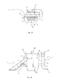
- FIG. 2A shows a view of the lid in an independent form wherein the lid is separated from the attachment shown in FIG. 1A .
- FIG. 2B indicates a view illustrating a state after removing the lid from the attachment shown in FIG. 1A .
- FIG. 3 denotes a view of the attachment shown in FIG. 1A wherein the attachment is connected to the dry cleaner.
- FIG. 4A shows a view of suction head wherein the suction head is retrieved from the attachment shown in FIG. 1A .
- FIG. 4B indicates a sectional view showing a state where the suction head shown in FIG. 4A is taken along the line X-X.
- a wet suction attachment 100 is provided with a sewage tank 1 for storing a sewage or liquid which was used to a cleaning operation, a solution tank 2 for containing a solution or cleaning liquid, and a separation processing unit 5 in a main container 110 .
- the attachment 100 is further provided with a gripper 6 , an extension tube 13 for connecting with a suction head 3 , and a coupling end portion 22 connected to an air hose (h) of a dry vacuum cleaner 101 , out of the main container 110 .
- the sewage tank 1 is arranged on the upper side in the main container 110 while the solution tank 2 on the lower side therein so as to be stacked each other.
- the sewage tank 1 is constructed to be circular in horizontal cross-section, and has a circular-shaped base surface portion 1 b and a conical periphery 1 a of increasing radius as it goes upward from the circular base portion 1 b , while the upper space thereof is covered by a lid 1 c which seals the inner space of the sewage tank 1 along the upper edge of the conical periphery 1 a.
- the base surface portion 1 b is formed by the partition plate 7 for partitioning the interior volume of the main container 110 up and down.
- the lid 1 c incorporates the separation processing unit 5 , as shown in FIG. 2B , and is secured to the main container 110 with being detachably from the sewage tank 1 through a plurality of (for example, 4 (four)) engaging portions 8 .
- the capacity of the solution tank 2 is set to be smaller than that of the sewage tank 1 .
- an operator even run out of all the solution from the solution tank 2 for example, it is possible to reliably prevent the solution containing dirt which has been collected, overflowing in the sewage tank 1 .
- each of the engaging portion 8 is constructed by a tongue 8 a which is pivoted, and a hook-like projection 8 b which is fitted to a locking hole (a 1 ) of the tongue 8 a so as to be hooked to be inserted therein.
- the separation processing unit 5 provided in the lid 1 c is constructed so as to sort or select the air from the solvent that is sucked with air into the sewage tank 1 through the suction head 3 as well as the dirt and dust contained in the solution, and then flow out toward the outlet tube 19 .
- the separation processing unit 5 is intended to carry out the air-water separator for separating air from liquid, and is constructed by a dish body 9 a , a fan 9 b which is rotated by the air flow, and a shaft portion 9 c for transmitting the rotation of the fan 9 b to the dish body 9 a .
- the dish body 9 a is formed so as to have a number of inclined slits (b 2 ) on the circumferential surface thereof, to stop the ingress of water into the dish body 9 a in by rotating, and to flow the air to the inside thereof through the slit (b 2 ). Air flowing into the inner area flows into the fan 9 b , and then is sucked through the outlet tube 19 by rotating the fan ( 9 b ).
- the solution tank 2 As shown in FIG. 1A , arranged on the lower side of the sewage tank 1 is the solution tank 2 .
- the solution tank 2 has a circular surface 2 a , and a bottom portion 2 b , and a top wall 2 c shares the partition plate 7 forming a bottom surface portion 1 b of the sewage tank 1 .
- a solution receiving unit 10 which has a solution supplying tube 10 a and a lid 10 b for openably closing an opening of the upper end thereof.
- the solution supplying tube 10 a is open into the circular surface 2 a at the lower end opening (c 1 ), and it is set higher than the top wall 2 c .
- the lid 2 b is formed with an air vent hole in order to enter and leave the air in the solution tank 2 .
- the lid 2 b is opened where the solution such as water, for example, is supplied in the solution tank 2 .
- the extension tube 13 is open through a nozzle 23 into the sewage tank 1 at the rear end through the conical periphery 1 a .
- An opening (d 1 ) of the nozzle 23 has a smaller opening area than the cross sectional area (d 2 ) through which air passes in the extension pipe 13 , the input flow rate of the sewage into the tank 1 is adapted to rise.
- the opening (d 1 ) of the nozzle 23 is open toward the circumferential direction along the air flow from the extension tube 13 to the conical peripheral surface 1 a . Outside of the nozzle 23 , it has become the guide wall 23 a to draw a continuous curve with the conical peripheral surface 1 a , the wastewater circulating in the sewage tank 1 is adapted to circulate beyond the top of the guide wall 23 a.
- the extension tube 13 is extended obliquely downward slightly forward from the sewage tank 1 , the suction head 3 is connected to the distal of the extension tube 13 .
- the suction head 3 has a mouth tube 3 a to be inserted into the extension pipe 13 and passage portion 3 b , the internal space of which is widened in the lateral direction gradually toward the mouth tube 3 a forward.
- a solution passage 15 is provided between the suction head 3 and the solution tank 2 .
- the suction head 3 has a flow rate adjuster 16 in the middle point thereof.
- the flow rate adjuster 16 is intended to be configured so as to elastically deform the middle portion of the solution passage 15 into a flat shape, and has a handle 16 a .
- the handle 16 a is operated so as to swing about the support shaft 17 , the solution passage 15 is sandwiched between the handle 16 a and the extension tube 13 , thereby being elastically deformed so as to confine the solution therein.
- FIG. 4A indicates the lower surface of the suction head 3
- FIG. 4B shows the X-X cross-section of the suction head 3
- a suction opening (f 1 ) which is configured by an elongated shape extending laterally, and through which suction negative pressure is guided by the extension tube 13 and an outflow opening (f 2 ) through which the solution is guided by the solution passage 15 are featured with sandwiching a boundary (f 3 ).
- Both sides of the boundary (f 3 ) which are opposing to each to each other define abysses of the suction opening (f 1 ) and the outflow opening (f 2 ), respectively, and its height set to be is higher than the recessed surrounding surface (f 4 ). Therefore, when the surrounding surface (f 4 ) abuts against the surface to be cleaned, a gap is formed between the lower surface of the boundary (f 3 ) and the surface to be cleaned. By the solution to flow from the outflow opening (f 2 ) to the suction opening (f 1 ) through the gap, the dirt soup or the like adhering to the surface to be cleaned is to be dissolved. Also, the brush would be provided, if necessary, on the surrounding surface (f 4 ).
- the gripper 6 is fixed on the rear side of the sewage tank 1 in a standing posture.
- the gripper 6 is fixed to the sewage tank 1 through a holding member 18 a , whereas, the holding member 18 b is disposed in a state of straddling the solution tank 2 , the gripper 6 is fixed to the main container 110 by both of the holding members in the bridge-like manner.
- the inside of the gripper 6 is defined by a tube which extends vertically.
- a socket 20 is fitted into an outlet tube 19 in a removable state with respect to the interior of the conduit of the gripper 6 . As shown in FIG.
- the lower end of the inner conduit of the gripper 6 is bent by 90 degrees with respect to a airflow direction in the horizontal direction, and the air hose (h) of the vacuum dry cleaner 101 via the coupling end portion 22 is connected.
- the gripper 6 is provided at a distance from the main container 110 between the solution tank 2 and the separation processing unit 5 . This position is corresponding to a state wherein the solution tank 2 is filled with the solution and wherein the main container 110 to which the lid 1 c is mounted is positioned on the horizontal side of the center of gravity of the main container 110 .
- the solution is supplied into the solution tank 2 by opening the lid 10 b of the solution receiving unit 10 , and then the lid 10 b is closed.
- the opening of the distal end of the air hose (h) of the electrical cleaner or dry vacuum cleaner 101 as the dry vacuum cleaner is fitted to the coupling end portion 22 .
- the operator is allowed to start by operating the switch (k) of the electrical cleaner 101 , and grips the gripper 6 by hand (j), to abut the suction opening (f 1 ) of the suction head 3 against the surface to be cleaned, such as the dirt surface of the carpet.
- the dry vacuum cleaner 101 is started to suck the air through the outlet tube 19 , the dish body 9 a , the sewage tank 1 and the suction head 3 .
- the solution passage 15 is set to be in the open state by operating the handle 16 a .
- the negative pressure of the suction opening (f 1 ) of the suction head 3 is propagated to the outlet opening (f 2 ) along the lower surface of the boundary (f 3 ).
- the solution in the solution tank 2 flows out from the outflow opening (f 2 ) onto the surface to be cleaned, thereby dissolving the dirt of soup or the like attached to the surface to be cleaned.
- the solution existing on the surface to be cleaned and mixed soil components in the solution and the dust scattered on the surface to be cleaned flow into the sewage tank 1 through the suction opening (f 1 ). They flow to move along the conical periphery 1 a in a state where the flow rate is increased to the nozzle.
- the swirl flow has been generated in the sewage tank 1 about the central axis thereof, by the rotation of the dish body 9 a .
- the centrifugation has been occurred in the sewage tank 1 , and then the sewage that has been centrifuged in the sewage tank 1 drops down into the solution tank 2 .
- the dish body 9 a splashes the sewage which has been falling down into the outlet tube 19 through the slits (b 2 ) by the centrifugal force due to rotation, thereby preventing the entry into the outlet tube 19 . Accordingly, the air flow in the outlet tube 19 is guided to the dry electric vacuum cleaner (k 1 ) through the gripper 6 and the coupling end 22 .
- the sewage tank 1 is disposed above the solution tank 2 . It is required that the depth of the sewage tank 1 is set to be deeper than that of the solution tank 2 , because the sewage tank 1 contains the dish body 9 a therein. Since the heavy goods or items such as the solution and the sewage are set to be positioned below the gripper 6 , whereas the separation processing unit 5 is set on the upper side of the gripper 6 , the center of gravity of the attachment 100 is positioned to be near the grip section 6 , it is easy maneuverability attachment 100 .
- the gripper 6 is responsible for this role.
- a size or diameter of the tube which controls the air volume of the conventional electric vacuum cleaner 101 is due to substantially the size of grip by the palm of the operator, the suction air of the dry vacuum cleaner 101 , which is introduced from the lower position where it does not interfere with the attachment 100 , is sent to the separation processing unit 5 by utilizing the internal space of the gripper 6 .
- the present invention is not limited to such a construction, it may be as a possible to separate the solution tank 2 from the body container 110 . More specifically, for example, a screw may be provided on the lower surface of the sewage tank 1 , the solution tank 2 may be attached to crowded screw from below to the sewage tank 2 .
- the gripper is provided with a vertical pipe therein, the upper side thereof is connected to the separation processing unit, while the lower side thereof is connected to the dry vacuum cleaner.
- the flow of the suction air is regulated as well as is intended to grip easily.
- the separation processing unit is set on the upper side and the solution tank filled with the solution therein on the lower side, the present invention has the effect of upper and lower weight balance is very good, thus the use of its industrial potential is extremely high.
Landscapes
- Engineering & Computer Science (AREA)
- Mechanical Engineering (AREA)
- Nozzles For Electric Vacuum Cleaners (AREA)
- Filters For Electric Vacuum Cleaners (AREA)
- Cleaning In General (AREA)
- Cleaning By Liquid Or Steam (AREA)
Abstract
Description
- Patent Document 1: Japanese Patent Publication No. 2005-131240
- Patent Document 2: Japanese Patent Publication No. 2002-315809
Claims (4)
Applications Claiming Priority (3)
| Application Number | Priority Date | Filing Date | Title |
|---|---|---|---|
| JP2012245380A JP5374631B1 (en) | 2012-11-07 | 2012-11-07 | Wet suction attachment |
| JP2012-245380 | 2012-11-07 | ||
| PCT/JP2013/080171 WO2014073625A1 (en) | 2012-11-07 | 2013-10-31 | Wet-type suction attachment |
Publications (2)
| Publication Number | Publication Date |
|---|---|
| US20150297048A1 US20150297048A1 (en) | 2015-10-22 |
| US9468344B2 true US9468344B2 (en) | 2016-10-18 |
Family
ID=49954964
Family Applications (1)
| Application Number | Title | Priority Date | Filing Date |
|---|---|---|---|
| US14/441,026 Expired - Fee Related US9468344B2 (en) | 2012-11-07 | 2013-10-31 | Wet suction attachment |
Country Status (4)
| Country | Link |
|---|---|
| US (1) | US9468344B2 (en) |
| JP (1) | JP5374631B1 (en) |
| CN (1) | CN104768439B (en) |
| WO (1) | WO2014073625A1 (en) |
Families Citing this family (11)
| Publication number | Priority date | Publication date | Assignee | Title |
|---|---|---|---|---|
| JP3201593U (en) * | 2015-10-06 | 2015-12-17 | 有限会社 川本技術研究所 | Outflow prevention valve |
| JP6082940B1 (en) * | 2016-01-15 | 2017-02-22 | 有限会社 川本技術研究所 | Suction head |
| GB2547698B (en) * | 2016-02-26 | 2020-11-25 | Tyroc Industries Ltd | Accessory for use with vacuum cleaners |
| CN109199229B (en) * | 2017-07-04 | 2024-04-09 | 苏州宝时得电动工具有限公司 | Suction head and dust collector |
| CN107468162B (en) * | 2017-09-04 | 2020-05-08 | 苏州海歌电器科技有限公司 | Convenient-to-push vacuum cleaner body |
| JP6391106B1 (en) * | 2017-10-20 | 2018-09-19 | 有限会社 川本技術研究所 | Suction head |
| EP3542693A1 (en) * | 2018-03-22 | 2019-09-25 | Hilti Aktiengesellschaft | Wet and/or dry vacuum cleaning unit |
| CN109528106B (en) * | 2018-12-19 | 2024-01-30 | 浙江东亿磁业有限公司 | Domestic multifunctional dust spraying and sucking water sucking machine |
| JP7515097B2 (en) * | 2019-10-25 | 2024-07-12 | アイリスオーヤマ株式会社 | Cleaning Equipment |
| EP3841939A1 (en) * | 2019-12-23 | 2021-06-30 | Koninklijke Philips N.V. | A wet and dry vacuum cleaner |
| JP7762968B2 (en) * | 2022-09-02 | 2025-10-31 | アイリスオーヤマ株式会社 | cleaning equipment |
Citations (11)
| Publication number | Priority date | Publication date | Assignee | Title |
|---|---|---|---|---|
| JPH01155950U (en) | 1988-03-28 | 1989-10-26 | ||
| JPH0229646U (en) | 1988-08-11 | 1990-02-26 | ||
| JPH0456440U (en) | 1990-09-25 | 1992-05-14 | ||
| JPH0513336U (en) | 1991-08-07 | 1993-02-23 | 株式会社家庭洗濯専門学院 | Connecting water remover for vacuum cleaner |
| US5210902A (en) | 1990-05-31 | 1993-05-18 | Goldstar, Co., Ltd. | Vacuum cleaner |
| JP2002315809A (en) | 2001-04-20 | 2002-10-29 | Izumi Products Co | Cleaner for caring |
| JP2005131240A (en) | 2003-10-31 | 2005-05-26 | Sharp Corp | Electric vacuum cleaner |
| JP2007014641A (en) | 2005-07-08 | 2007-01-25 | Akihiko No | Hose joint for drum |
| JP2007054352A (en) | 2005-08-25 | 2007-03-08 | Matsushita Electric Ind Co Ltd | Electric vacuum cleaner |
| JP2008049102A (en) | 2006-08-28 | 2008-03-06 | Aun:Kk | Simplified vacuum apparatus |
| JP2010142390A (en) | 2008-12-18 | 2010-07-01 | Kondo Kogyo Kk | Liquid-fluid substance processing filter unit |
-
2012
- 2012-11-07 JP JP2012245380A patent/JP5374631B1/en not_active Expired - Fee Related
-
2013
- 2013-10-31 US US14/441,026 patent/US9468344B2/en not_active Expired - Fee Related
- 2013-10-31 CN CN201380058245.3A patent/CN104768439B/en not_active Expired - Fee Related
- 2013-10-31 WO PCT/JP2013/080171 patent/WO2014073625A1/en not_active Ceased
Patent Citations (12)
| Publication number | Priority date | Publication date | Assignee | Title |
|---|---|---|---|---|
| JPH01155950U (en) | 1988-03-28 | 1989-10-26 | ||
| JPH0229646U (en) | 1988-08-11 | 1990-02-26 | ||
| US5210902A (en) | 1990-05-31 | 1993-05-18 | Goldstar, Co., Ltd. | Vacuum cleaner |
| JP2721280B2 (en) | 1990-05-31 | 1998-03-04 | エルジー電子株式会社 | Vacuum cleaner |
| JPH0456440U (en) | 1990-09-25 | 1992-05-14 | ||
| JPH0513336U (en) | 1991-08-07 | 1993-02-23 | 株式会社家庭洗濯専門学院 | Connecting water remover for vacuum cleaner |
| JP2002315809A (en) | 2001-04-20 | 2002-10-29 | Izumi Products Co | Cleaner for caring |
| JP2005131240A (en) | 2003-10-31 | 2005-05-26 | Sharp Corp | Electric vacuum cleaner |
| JP2007014641A (en) | 2005-07-08 | 2007-01-25 | Akihiko No | Hose joint for drum |
| JP2007054352A (en) | 2005-08-25 | 2007-03-08 | Matsushita Electric Ind Co Ltd | Electric vacuum cleaner |
| JP2008049102A (en) | 2006-08-28 | 2008-03-06 | Aun:Kk | Simplified vacuum apparatus |
| JP2010142390A (en) | 2008-12-18 | 2010-07-01 | Kondo Kogyo Kk | Liquid-fluid substance processing filter unit |
Non-Patent Citations (1)
| Title |
|---|
| International Search Report dated Feb. 4, 2014 issued in correspondig application No. PCT/JP2013/080171. |
Also Published As
| Publication number | Publication date |
|---|---|
| JP5374631B1 (en) | 2013-12-25 |
| JP2014094026A (en) | 2014-05-22 |
| CN104768439B (en) | 2017-03-29 |
| CN104768439A (en) | 2015-07-08 |
| WO2014073625A1 (en) | 2014-05-15 |
| US20150297048A1 (en) | 2015-10-22 |
Similar Documents
| Publication | Publication Date | Title |
|---|---|---|
| US9468344B2 (en) | Wet suction attachment | |
| US11191402B2 (en) | Cleaning device | |
| CN103079445B (en) | The recycling can assembly with pour spout for suction cleaning machine | |
| JP2016511671A (en) | Surface cleaning device | |
| JP6082940B1 (en) | Suction head | |
| JP3201593U (en) | Outflow prevention valve | |
| KR20230067663A (en) | wet cleaning device | |
| CN104367266A (en) | Handheld dust collector | |
| US9237835B2 (en) | Collecting apparatus of sucked materials for vacuum cleaner appliances | |
| CN108135410B (en) | Portable Hard Surface Cleaner | |
| KR102328244B1 (en) | Cleaner | |
| KR20060128387A (en) | Vacuum cleaner | |
| JP3210087U (en) | Wet cleaner | |
| KR20240030125A (en) | Station for vacumm cleaner | |
| KR101147778B1 (en) | A vacuum cleaner | |
| KR101597228B1 (en) | vacuum cleaner | |
| CN109717793B (en) | Electric vacuum cleaner | |
| KR20090049946A (en) | Vacuum cleaner and its foreign body separating device | |
| KR20110077921A (en) | Dust suction device of vacuum cleaner | |
| KR20120004102A (en) | Dust collection assembly of vacuum cleaner |
Legal Events
| Date | Code | Title | Description |
|---|---|---|---|
| AS | Assignment |
Owner name: KAWAMOTO TECHNICAL LABORATORY INC., JAPAN Free format text: ASSIGNMENT OF ASSIGNORS INTEREST;ASSIGNOR:KAWAMOTO, EIICHI;REEL/FRAME:035579/0920 Effective date: 20150424 Owner name: OFFICE TOMIOKA INC., JAPAN Free format text: ASSIGNMENT OF ASSIGNORS INTEREST;ASSIGNOR:KAWAMOTO, EIICHI;REEL/FRAME:035579/0920 Effective date: 20150424 |
|
| STCF | Information on status: patent grant |
Free format text: PATENTED CASE |
|
| FEPP | Fee payment procedure |
Free format text: MAINTENANCE FEE REMINDER MAILED (ORIGINAL EVENT CODE: REM.); ENTITY STATUS OF PATENT OWNER: LARGE ENTITY |
|
| LAPS | Lapse for failure to pay maintenance fees |
Free format text: PATENT EXPIRED FOR FAILURE TO PAY MAINTENANCE FEES (ORIGINAL EVENT CODE: EXP.); ENTITY STATUS OF PATENT OWNER: LARGE ENTITY |
|
| STCH | Information on status: patent discontinuation |
Free format text: PATENT EXPIRED DUE TO NONPAYMENT OF MAINTENANCE FEES UNDER 37 CFR 1.362 |
|
| FP | Expired due to failure to pay maintenance fee |
Effective date: 20201018 |