US9467397B2 - Port mode synchronization between switches - Google Patents
Port mode synchronization between switches Download PDFInfo
- Publication number
- US9467397B2 US9467397B2 US14/403,882 US201314403882A US9467397B2 US 9467397 B2 US9467397 B2 US 9467397B2 US 201314403882 A US201314403882 A US 201314403882A US 9467397 B2 US9467397 B2 US 9467397B2
- Authority
- US
- United States
- Prior art keywords
- switch
- mode
- port
- request packet
- ethernet
- Prior art date
- Legal status (The legal status is an assumption and is not a legal conclusion. Google has not performed a legal analysis and makes no representation as to the accuracy of the status listed.)
- Active
Links
- 239000004744 fabric Substances 0.000 claims abstract description 118
- 230000004044 response Effects 0.000 claims abstract description 49
- 238000000034 method Methods 0.000 claims description 19
- 238000010586 diagram Methods 0.000 description 6
- 239000004606 Fillers/Extenders Substances 0.000 description 2
- 125000004122 cyclic group Chemical group 0.000 description 2
- 238000003780 insertion Methods 0.000 description 1
- 230000037431 insertion Effects 0.000 description 1
- 230000011664 signaling Effects 0.000 description 1
- 230000001360 synchronised effect Effects 0.000 description 1
Images


Classifications
-
- H—ELECTRICITY
- H04—ELECTRIC COMMUNICATION TECHNIQUE
- H04L—TRANSMISSION OF DIGITAL INFORMATION, e.g. TELEGRAPHIC COMMUNICATION
- H04L49/00—Packet switching elements
- H04L49/15—Interconnection of switching modules
-
- H—ELECTRICITY
- H04—ELECTRIC COMMUNICATION TECHNIQUE
- H04L—TRANSMISSION OF DIGITAL INFORMATION, e.g. TELEGRAPHIC COMMUNICATION
- H04L12/00—Data switching networks
- H04L12/28—Data switching networks characterised by path configuration, e.g. LAN [Local Area Networks] or WAN [Wide Area Networks]
- H04L12/40—Bus networks
- H04L12/407—Bus networks with decentralised control
- H04L12/413—Bus networks with decentralised control with random access, e.g. carrier-sense multiple-access with collision detection [CSMA-CD]
-
- H—ELECTRICITY
- H04—ELECTRIC COMMUNICATION TECHNIQUE
- H04L—TRANSMISSION OF DIGITAL INFORMATION, e.g. TELEGRAPHIC COMMUNICATION
- H04L49/00—Packet switching elements
- H04L49/35—Switches specially adapted for specific applications
- H04L49/351—Switches specially adapted for specific applications for local area network [LAN], e.g. Ethernet switches
-
- H—ELECTRICITY
- H04—ELECTRIC COMMUNICATION TECHNIQUE
- H04L—TRANSMISSION OF DIGITAL INFORMATION, e.g. TELEGRAPHIC COMMUNICATION
- H04L49/00—Packet switching elements
- H04L49/60—Software-defined switches
- H04L49/602—Multilayer or multiprotocol switching, e.g. IP switching
-
- H—ELECTRICITY
- H04—ELECTRIC COMMUNICATION TECHNIQUE
- H04L—TRANSMISSION OF DIGITAL INFORMATION, e.g. TELEGRAPHIC COMMUNICATION
- H04L49/00—Packet switching elements
- H04L49/65—Re-configuration of fast packet switches
Definitions
- a stack switch system i.e., a switch fabric
- fabric ports of switches are communicatively coupled to each other and send fabric packets via respective ports.
- a chip typically generates a fabric packet by adding a fabric header to an Ethernet packet to be forwarded in the switch fabric.
- the switch containing the Ethernet port often discards the fabric packet due to the existence of a cyclic redundancy check (CRC) error.
- CRC cyclic redundancy check
- FIG. 1 is a schematic diagram illustrating a signaling process of port mode synchronization between switches according to an example of the present disclosure.
- FIG. 2A is a schematic diagram illustrating the format of a mode switch request packet according to an example of the present disclosure.
- FIG. 2B is a schematic diagram illustrating the format of a mode switch request packet according to another example of the present disclosure.
- FIG. 3 is a schematic diagram illustrating the structure of a stack switch system according to an example of the present disclosure.
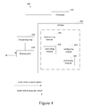
- FIG. 4 is a schematic diagram illustrating the structure of a network device according to an example of the present disclosure.
- FIG. 5 is a schematic diagram illustrating the structure of a network device according to another example of the present disclosure.
- the present disclosure is described by referring mainly to an example thereof.
- numerous specific details are set forth in order to provide a thorough understanding of the present disclosure. It will be readily apparent however, that the present disclosure may be practiced without limitation to these specific details. In other instances, some methods and structures have not been described in detail so as not to unnecessarily obscure the present disclosure.
- the terms “a” and “an” are intended to denote at least one of a particular element.
- the term “includes” means includes but not limited to, the term “including” means including but not limited to.
- the term “based on” means based at least in part on.
- the terms “primary” and “secondary” are not intended to denote hierarchy, but instead, may be construed as distinguishing peer elements from each other.
- the primary switches may be Controlling Bridges (CBs) and the secondary switches may be Port Extenders (PEs).
- CBs Controlling Bridges
- PEs Port Extenders
- the primary switches may connect to each other in a ring or chain topology over stacking links and each of the secondary switches may connect to one or more primary switches via physical links.
- a port on a primary switch is referred to as a “primary port” and a port on a secondary switch is referred to as a “secondary port”.
- each port of the network switches is configured based on factory settings, that is, each port is configured to operate in an Ethernet mode by default.
- the ports of network switches are typically not configured to operate in a fabric mode, i.e., within a switch fabric or a stack switch system.
- the port modes of the ports of network switches in a switch fabric or, equivalently, a stack switch system may automatically be synchronized with each other to operate in the fabric mode.
- the port mode synchronization process may include the following operations.
- the primary port of the primary switch may be configured to operate in a fabric mode. Specifically, the primary port of the primary switch may be manually configured to operate in the fabric mode.
- the primary switch may generate a mode switch request packet and may send the mode switch request packet to the secondary switch via the primary port.
- the primary switch may check the mode state of the primary port.
- the primary switch may configure a register of the primary port as an Ethernet packet check mode, may generate the check information of the mode switch request packet based on the Ethernet packet check mode indicated by the register of the primary port, and may generate the mode switch request packet through insertion of information contained in an Ethernet payload part of the mode switch request packet to cause the secondary switch to change the secondary port from operating in an Ethernet mode to the fabric mode.
- the information is contained in a fabric header of the Ethernet payload part of the mode switch request packet.
- the information is contained in a packet identifier in the Ethernet payload part of the mode switch request packet.
- the primary switch may send the mode switch request packet to the secondary switch via the primary port. After sending the mode switch request packet, the primary switch may configure the register of the primary port in a fabric packet check mode and may wait for a mode switch response, which may be a mode switch response packet, from the secondary switch.
- the mode switch request may be an Ethernet packet, and an example of a format of the mode switch request is shown in FIG. 2A .
- the fabric header may be contained in the Ethernet payload of the mode switch request packet and may include a source port number, a source chip number, a destination port number, a destination chip number, and a local priority of the packet. According to an example, the fabric header may be used to instruct the primary switch receiving the packet to change its port from operating in the Ethernet mode to the fabric mode. In another example, shown in FIG.
- the Ethernet payload part of the mode switch request may carry a packet identifier which instructs a receiving switch (e.g., the secondary switch) of the packet to change a receiving port (e.g., the secondary port) from operating in the Ethernet mode to the fabric mode.
- a receiving switch e.g., the secondary switch
- a receiving port e.g., the secondary port
- the secondary switch may change the secondary port from operating in the Ethernet mode to the fabric mode based on the received mode switch request packet.
- the secondary switch may perform a cyclic redundancy check (CRC) for the mode switch request packet based on the Ethernet packet check mode indicated by a register of the secondary port. After the CRC is passed, the secondary switch may change the secondary port from operating in the Ethernet mode to the fabric mode based on the fabric header in the mode switch request packet. Prior to this change, however, the CPU of the secondary switch may parse the mode switch request packet and may obtain the fabric header. Due to the mode switch request packet being an Ethernet packet, the secondary port may operate in the Ethernet mode and the register of the secondary port may indicate the Ethernet check mode, the secondary switch may implement the CRC for the mode switch request packet correctly. Because the secondary port switch may be unable to parse the fabric header contained in the Ethernet payload part of the mode switch request packet, report the mode switch request packet may be reported to the CPU of the secondary switch, and the CPU may parse the fabric header through software.
- CRC cyclic redundancy check
- the secondary switch may learn, based on the fabric header, that the primary port has been configured to operate in the fabric mode, and may then change the secondary port from operating the Ethernet mode to the fabric mode.
- the secondary switch may perform a CRC check to the mode switch request packet based on the Ethernet packet checking mode indicated by a register of the secondary port. After the CRC check is passed, the secondary switch may parse the mode switching request to obtain the packet identifier carried in the Ethernet payload part, and may change the secondary port through which the mode switch request packet is received from the Ethernet mode to the fabric mode according to the packet identifier.
- the mode switch request packet may be an Ethernet packet and the CRC checking mode of the mode switch request packet may be the Ethernet packet checking mode.
- the receiving port of the mode switching request may be configured under factory settings, i.e., the Ethernet mode, and the register of the receiving port may indicate the Ethernet packet checking mode. Therefore, the secondary switch may check and parse the mode switch request packet correctly.
- the secondary switch may send a mode switch response packet to the primary switch via the secondary port, and the primary switch may terminate the port mode synchronization between the two switches after receiving the mode switch response packet.
- the secondary switch may send the mode switch response packet via the secondary port to indicate that the secondary port has been configured to operate in the fabric mode.
- the mode switch response packet may be a fabric packet. Because the register of the primary port has been configured to operate in the fabric packet check mode, the primary switch may correctly check and parse the mode switch response packet.
- the secondary switch may be unable to receive the mode switch request packet from the primary switch, so that the primary switch may be unable to receive the mode switch response packet from the secondary switch for a long time after the mode switch request packet is sent.
- the port mode synchronization between the primary and secondary switches may further include the following operations.
- the primary switch may generate a new mode switch request packet, and may send the new mode switch request packet to the secondary switch via the primary port of the secondary switch. If the primary switch receives the mode switch response packet from the secondary switch within the predetermined time after the new mode switch request packet is sent to the secondary switch, the primary switch may terminate the process of the port mode synchronization between the two switches.
- a specific implementation of generating the mode switch request packet and sending the mode switch request packet to the secondary switch via the port of the primary switch refers to block 102 and is not illustrated in detail herein.
- the primary switch may start a timer.
- the primary switch may delete the timer after the mode switch response packet is received from the secondary switch. Expiration of the timer may be an indication that the primary switch did not receive the mode switch response packet from the secondary switch within the duration of the timer, and thus it may be uncertain whether the port of the secondary switch has been changed from operating in the Ethernet mode to the fabric mode.
- the primary switch may resend the mode switch request packet to the secondary switch to request the primary switch to change the port of the secondary switch from operating in the Ethernet mode to the fabric mode, thereby ensuring port mode synchronization between the secondary switch and the primary switch.
- the duration of the timer may be determined based on the requirements of switch performance and application scenes.
- the primary switch may configure its port to operate in the fabric mode and may send the mode switch request packet having the Ethernet format to the secondary switch, and the information to cause the change may be contained in the Ethernet payload part of the mode switch request packet.
- the secondary switch may automatically change its port from operating in the Ethernet mode to the fabric mode based on the information contained in the mode switch request packet.
- This automatic switching may solve the problem of automatic negotiation between the Ethernet port of a switch and the fabric port of another switch and may enable the fabric packet to be correctly received and parsed, while facilitating the forwarding of the fabric packet.
- the implementation of port mode synchronization between switches may be applied to a stack switch system.
- the stack switch system may include multiple Controlling Bridges (CBs) and multiple Port Extenders (PEs), and the ports of the CBs and PEs may all be configured to operate in the Ethernet mode by default.
- CBs Controlling Bridges
- PEs Port Extenders
- the ports of the PEs and the ports of the CBs may be connected to each other according to a connection relationship shown in FIG. 3 to establish a stack switch system.
- CB 1 -CB 3 connect to each other in a ring topology via stacking links.
- the PE 1 -PE 4 do not directly connected to each other.
- the CB 1 and the PE 1 in the stack switch system are taken as exemplary switches to describe the port mode synchronization.
- ports 311 - 313 on CB 1 may connect to PE 1 -PE 3 respectively
- ports 321 - 323 on PE 1 may connect to CB 1 -CB 3 respectively.
- Ports 311 - 313 may all be configured to operate in the fabric mode.
- CB 1 may configure the register of port 311 to operate in an Ethernet packet check mode, may generate the check information of a mode switch request packet based on the Ethernet packet check mode indicated by the register of port 311 , and may send the mode switch request packet to PE 1 via port 311 , where the Ethernet payload part of the mode switch request packet may contain information to cause the change, e.g., a fabric header or a packet identifier.
- PE 1 may check the mode switch request packet based on the Ethernet packet check mode indicated by the register of port 311 of PE 1 .
- PE 1 may change port 321 from operating in the Ethernet mode to the fabric mode based on the information after parsing the mode switch request packet and obtaining the information (fabric header or packet identifier) contained in the mode switch request packet, thereby realizing mode synchronization between port 311 and port 321 .
- CB 1 may also automatically perform port mode synchronization with PE 2 and PE 3 based on the above process.
- CB 2 or CB 3 may automatically perform port mode synchronization with PE 1 , PE 2 and PE 3 based on the above process.
- the implementation of port mode synchronization between switches may decrease user configuration operations and enable realization of plug and play dynamic stack application.
- port mode synchronization between switches provided by an example of the present disclosure may be applied to, but is not limited to, a stack switch system.
- the network switch 400 may include a primary port 410 interconnecting the switch 400 with a secondary port of a peer switch; a forwarding chip 420 , a processor 430 , and a storage 440 coupled with the processor 420 .
- the chip 420 transmits a mode switch request packet generated by the processor 430 to the primary port 410 for sending the mode switch request packet to the peer switch; and transmits a mode switch response packet received at the primary port 410 to the processor 430 for analyzing and processing.
- the storage 440 comprises one or more program modules to be executed by the processor 430 , the one or more program modules comprise: a checking module 441 , a controlling module 442 , a configuring module 443 , and a processing module 444 .
- the checking module 441 may check whether the primary port interconnecting to the peer switch is configured to operate in a fabric mode.
- the controlling module 442 may send a first indication to the configuring module 443 and may send a second indication to the processing module 444 after the checking module 441 detects that the primary port is configured to operate in the fabric mode.
- the controlling module 442 may also send a third indication to the configuring module 443 after the processing module 444 sends the mode switch request packet, and may wait for the mode switch response packet from the peer switch.
- the controller module 442 may further terminate the process of port mode synchronication between the switch and the peer switch after the mode switch response packet is received from the peer switch via the primary port, where the mode switch response packet is sent by the peer switch after the peer switch changes the port of the peer switch from operating in the Ethernet mode to the fabric mode based on the information contained in the mode switch request packet.
- the configuring module 443 may configure the register of the primary port to operate in an Ethernet packet check mode based on the first indication sent by the controlling module 442 and may configure the register of the primary port to operate in the fabric mode based on the third indication sent by the controlling module 442 .
- the processing module 44 may, based on the second indication sent by the controlling module 442 , generate the check information of the mode switch request packet based on the Ethernet packet check mode indicated by the register of the primary port, and may send the mode switch request packet, where the Ethernet payload part of the mode switch request packet contains the information (fabric header or packet identifier) for instructing the peer switch to change its interconnecting port from operating in the Ethernet mode to the fabric mode.
- the controlling module 442 may further, after the processing module 44 sends the mode switch request packet, if the mode switch response packet from the peer switch is not received via the primary port within a predetermined time, send the first indication to the configuring module 443 , send the second indication to the processing module 444 , send the third indication to the configuring module 443 after the processsing module 44 sends the mode switch request packet, and wait for the mode switch response packet from the peer switch.
- the network switch may include a secondary port 510 interconnecting the switch 500 with a primary port of a peer switch; a forwarding chip 520 , a processor 530 , and a storage 540 coupled with the processor 530 .
- the forwarding chip 520 transmits a mode switch request packet received at the secondary port 510 to the processor 530 for analyzing and processing, and transmits a mode switch response packet generated by the processor 530 to the secondary port 510 for sending the mode switch request packet to the peer switch;
- the storage 540 comprises one or more program modules to be executed by the processor 530 , the one or more program modules comprise: a receiving module 541 , a processing module 542 , and a sending module 543 .
- the receiving module 541 may receive a mode switch request packet received at the secondary port 510 , where the mode switch request packet may be sent by the peer switch and the mode switch request packet may be an Ethernet packet.
- the processing module 542 may change the secondary port 510 from operating in an Ethernet mode to the fabric mode based on information (fabric header or packet identifier) contained in the mode switch request packet.
- the sending module 543 may send a mode switch response packet after the processing module 542 changes the secondary port from operating in the Ethernet mode to the fabric mode.
- the processing module 542 may check the mode switch request packet based on an Ethernet packet check mode indicated by the register of the secondary port, report the mode switch request packet to the processor 530 (CPU of the switch) after the check is passed, and change the secondary port of the switch from operating in the Ethernet mode to the fabric mode based on the information (fabric header or packet identifier) after the processory 530 (CPU) parses the mode switch request packet and obtains the information (fabric header or packet identifier) in the Ethernet payload of the mode switch request packet.
- An example of the present disclosure may also provide a stack switch system, which includes a primary switch and a secondary switch.
- the primary port of the primary switch and the secondary port of the secondary switch may be connected to each other, and the primary port may be configured to operate in a fabric mode.
- the primary switch may configure the register of the primary port as an Ethernet packet check mode and may generate the check information of the mode switch request packet based on the Ethernet packet check mode indicated by the register of the primary port.
- the primary switch may also send the mode switch request packet to the secondary switch via the primary port, configure the register of the primary port as the fabric mode, and wait for a mode switch response packet from the secondary switch, where the Ethernet payload part of the mode switch request packet contains information (fabric header or packet identifier) for instructing the secondary switch to change the secondary port from operating in an Ethernet mode to the fabric mode.
- the primary switch may further terminate the port mode synchronization after the mode switch response packet is received at the primary port.
- the secondary switch may receive the mode switch request packet from the primary switch via the secondary port, change the secondary port from operating in the Ethernet mode to the fabric mode based on the information (fabric header or packet identifier) in the mode switch request packet, and send the mode switch response packet to the primary switch via the secondary port.
- the primary switch may further periodically configure the register of the port of the primary switch to operate in the Ethernet packet check mode, generate the check information of the mode switch request packet based on the Ethernet packet check mode indicated by the register of the port of the primary switch, send the mode switch request packet to the secondary switch via the primary port, configure the register of the primary port to operate in the fabric mode, and wait for a mode switch response packet from the secondary switch, if the primary switch does not receive the mode switch response packet from the secondary switch within each predetermined time
- the secondary switch may check the mode switch request packet based on the Ethernet packet check mode indicated by the register of the secondary port, and may report the mode switch request packet to the CPU of the secondary switch after the check is passed.
- the secondary switch may also change the secondary port from operating in the Ethernet mode to the fabric mode based on the information (fabric header or packet identifier) after the CPU parses the mode switch request packet and obtains the information (fabric header or packet identifier) contained in the Ethernet payload part of the mode switch request packet.
- the first switch may send the mode switch request packet containing the information (fabric header or packet identifier) to the peer switch via the port of the first switch, to request the peer switch to change the port of the peer switch from operating in the Ethernet mode to the fabric mode.
- the mode switch request packet containing the information (fabric header or packet identifier)
- the peer switch may change the port of the peer switch from operating in the Ethernet mode to the fabric mode.
- the methods and modules disclosed herein may be realized by software accompanied by general hardware platforms, or by hardware.
- the methods and modules disclosed herein may be implemented by logic circuitry such as one or more application specific integrated circuits (ASICs) or integrated circuits or as machine readable instructions stored in a memory and executable by a processor.
- ASICs application specific integrated circuits
- the methods disclosed herein may be in the form of a computer software product, and the computer software product may be stored in a computer readable storage medium and may include machine-readable instructions to make a network switch (such as a switch or router) perform the methods disclosed herein.
Landscapes
- Engineering & Computer Science (AREA)
- Computer Networks & Wireless Communication (AREA)
- Signal Processing (AREA)
- Small-Scale Networks (AREA)
Abstract
Description
Claims (13)
Applications Claiming Priority (7)
| Application Number | Priority Date | Filing Date | Title |
|---|---|---|---|
| CN201210426838.8A CN103795518B (en) | 2012-10-31 | 2012-10-31 | A kind of equipment room port mode synchronous method, equipment and system |
| CN201210427003.4A CN103795557B (en) | 2012-10-31 | 2012-10-31 | Method, device, and system for synchronizing port modes between devices |
| CN201210426838 | 2012-10-31 | ||
| CN201210426838.8 | 2012-10-31 | ||
| CN201210427003 | 2012-10-31 | ||
| CN201210427003.4 | 2012-10-31 | ||
| PCT/CN2013/086283 WO2014067470A1 (en) | 2012-10-31 | 2013-10-31 | Port mode synchronization between switches |
Publications (2)
| Publication Number | Publication Date |
|---|---|
| US20150350111A1 US20150350111A1 (en) | 2015-12-03 |
| US9467397B2 true US9467397B2 (en) | 2016-10-11 |
Family
ID=50626509
Family Applications (1)
| Application Number | Title | Priority Date | Filing Date |
|---|---|---|---|
| US14/403,882 Active US9467397B2 (en) | 2012-10-31 | 2013-10-31 | Port mode synchronization between switches |
Country Status (2)
| Country | Link |
|---|---|
| US (1) | US9467397B2 (en) |
| WO (1) | WO2014067470A1 (en) |
Families Citing this family (7)
| Publication number | Priority date | Publication date | Assignee | Title |
|---|---|---|---|---|
| CN104427012B (en) | 2013-09-04 | 2018-12-11 | 新华三技术有限公司 | Port negotiation method and apparatus |
| US10334334B2 (en) * | 2016-07-22 | 2019-06-25 | Intel Corporation | Storage sled and techniques for a data center |
| US10608957B2 (en) * | 2017-06-29 | 2020-03-31 | Cisco Technology, Inc. | Method and apparatus to optimize multi-destination traffic over etherchannel in stackwise virtual topology |
| CN114650113B (en) * | 2020-12-18 | 2024-07-16 | 华为技术有限公司 | Method and device for selecting clock source |
| CN114978788B (en) * | 2022-05-25 | 2023-04-18 | 西安电子科技大学 | Network switch based on dual-mode switching |
| CN115225590B (en) * | 2022-05-25 | 2023-08-04 | 西安电子科技大学 | Dual-mode hundred-mega network switch system |
| KR102540094B1 (en) * | 2022-11-17 | 2023-06-05 | 에스지에이솔루션즈 주식회사 | User access control and access blocking apparatus using web application proxy |
Citations (6)
| Publication number | Priority date | Publication date | Assignee | Title |
|---|---|---|---|---|
| US20010005383A1 (en) * | 1996-12-25 | 2001-06-28 | Hitachi, Ltd. | IP switch, interface circuit and ATM switch used for IP switch, and IP switch network system |
| US7079525B1 (en) | 2000-04-27 | 2006-07-18 | Cisco Technology, Inc. | Network switch having a hybrid switch architecture |
| US20090296726A1 (en) | 2008-06-03 | 2009-12-03 | Brocade Communications Systems, Inc. | ACCESS CONTROL LIST MANAGEMENT IN AN FCoE ENVIRONMENT |
| CN102123467A (en) | 2011-03-02 | 2011-07-13 | 深圳市科陆电子科技股份有限公司 | Method for multi-channel self-adaptive switch during terminal communication |
| CN102215067A (en) | 2011-07-11 | 2011-10-12 | 福建星网锐捷网络有限公司 | Port auto negotiation method and device |
| US20140044126A1 (en) * | 2012-08-08 | 2014-02-13 | Cisco Technology, Inc. | Scalable Media Access Control Protocol Synchronization Techniques for Fabric Extender Based Emulated Switch Deployments |
-
2013
- 2013-10-31 WO PCT/CN2013/086283 patent/WO2014067470A1/en not_active Ceased
- 2013-10-31 US US14/403,882 patent/US9467397B2/en active Active
Patent Citations (6)
| Publication number | Priority date | Publication date | Assignee | Title |
|---|---|---|---|---|
| US20010005383A1 (en) * | 1996-12-25 | 2001-06-28 | Hitachi, Ltd. | IP switch, interface circuit and ATM switch used for IP switch, and IP switch network system |
| US7079525B1 (en) | 2000-04-27 | 2006-07-18 | Cisco Technology, Inc. | Network switch having a hybrid switch architecture |
| US20090296726A1 (en) | 2008-06-03 | 2009-12-03 | Brocade Communications Systems, Inc. | ACCESS CONTROL LIST MANAGEMENT IN AN FCoE ENVIRONMENT |
| CN102123467A (en) | 2011-03-02 | 2011-07-13 | 深圳市科陆电子科技股份有限公司 | Method for multi-channel self-adaptive switch during terminal communication |
| CN102215067A (en) | 2011-07-11 | 2011-10-12 | 福建星网锐捷网络有限公司 | Port auto negotiation method and device |
| US20140044126A1 (en) * | 2012-08-08 | 2014-02-13 | Cisco Technology, Inc. | Scalable Media Access Control Protocol Synchronization Techniques for Fabric Extender Based Emulated Switch Deployments |
Non-Patent Citations (1)
| Title |
|---|
| International Search Report and Written Opinion dated Jan. 30, 2014 issued on PCT Patent Application No. PCT/CN2013/086283 dated Oct. 31, 2013, The State Intellectual Property Office, P.R. China. |
Also Published As
| Publication number | Publication date |
|---|---|
| WO2014067470A1 (en) | 2014-05-08 |
| US20150350111A1 (en) | 2015-12-03 |
Similar Documents
| Publication | Publication Date | Title |
|---|---|---|
| US9467397B2 (en) | Port mode synchronization between switches | |
| JP5350461B2 (en) | Enhanced traffic indication in connection failure management | |
| US9264314B2 (en) | Method, system, and switch for making bridge in MSTP join region | |
| EP2555476A1 (en) | Method, system and device for protecting multicast in communication network | |
| US20130254356A1 (en) | Systems and methods for recovery from network changes | |
| CN105763359A (en) | Distributed Bidirectional Forwarding Detection Protocol (d-bfd) For Cluster Of Interconnected Switches | |
| EP2798800B1 (en) | Expanding member ports of a link aggregation group between clusters | |
| CN106549774A (en) | A kind of link failure report method and forwarding unit based on software defined network | |
| CN103534982A (en) | Method, device and network virtualization system for protecting service reliability | |
| CN105656645A (en) | Decision making method and device for fault processing of stacking system | |
| US10862735B2 (en) | Method and apparatus for implementing operation, administration, and maintenance function | |
| CN101729426B (en) | Method and system for quickly switching between master device and standby device of virtual router redundancy protocol (VRRP) | |
| WO2018188425A1 (en) | Vxlan single-homing and dual-homing hybrid access method and apparatus, pe device and storage medium | |
| CN104270309A (en) | A method for implementing multi-hop BFD under an IP RAN device | |
| WO2017054547A1 (en) | Bidirectional forwarding detection method and apparatus | |
| WO2022063207A1 (en) | Time synchronization failure processing method, device and system | |
| WO2012088910A1 (en) | Method and system for detecting connectivity fault | |
| CN103795518A (en) | Method, device, and system for synchronizing port modes between devices | |
| CN102239670B (en) | A load sharing method and device | |
| JP2012151604A (en) | Provider network and provider edge device | |
| CN106411730B (en) | A kind of message forwarding method and device | |
| US9762510B2 (en) | Relay system and switching device | |
| CN101227393B (en) | Method and apparatus for anti-error connecting of switch stack | |
| US8144574B1 (en) | Distributed control packet processing | |
| CN104754762B (en) | Method, controller and system for automatically discovering controllers in software-defined network |
Legal Events
| Date | Code | Title | Description |
|---|---|---|---|
| AS | Assignment |
Owner name: HANGZHOU H3C TECHNOLOGIES CO., LTD., CHINA Free format text: ASSIGNMENT OF ASSIGNORS INTEREST;ASSIGNORS:XIU, YIHONG;QI, ZHENGLIN;LIU, DAOGUI;AND OTHERS;REEL/FRAME:034386/0084 Effective date: 20131105 |
|
| AS | Assignment |
Owner name: HEWLETT PACKARD ENTERPRISE DEVELOPMENT LP, TEXAS Free format text: ASSIGNMENT OF ASSIGNORS INTEREST;ASSIGNORS:H3C TECHNOLOGIES CO., LTD.;HANGZHOU H3C TECHNOLOGIES CO., LTD.;REEL/FRAME:039767/0263 Effective date: 20160501 |
|
| STCF | Information on status: patent grant |
Free format text: PATENTED CASE |
|
| MAFP | Maintenance fee payment |
Free format text: PAYMENT OF MAINTENANCE FEE, 4TH YEAR, LARGE ENTITY (ORIGINAL EVENT CODE: M1551); ENTITY STATUS OF PATENT OWNER: LARGE ENTITY Year of fee payment: 4 |
|
| MAFP | Maintenance fee payment |
Free format text: PAYMENT OF MAINTENANCE FEE, 8TH YEAR, LARGE ENTITY (ORIGINAL EVENT CODE: M1552); ENTITY STATUS OF PATENT OWNER: LARGE ENTITY Year of fee payment: 8 |