US946733A - Means for soldering end seams of cans. - Google Patents
Means for soldering end seams of cans. Download PDFInfo
- Publication number
- US946733A US946733A US42248108A US1908422481A US946733A US 946733 A US946733 A US 946733A US 42248108 A US42248108 A US 42248108A US 1908422481 A US1908422481 A US 1908422481A US 946733 A US946733 A US 946733A
- Authority
- US
- United States
- Prior art keywords
- track
- cans
- runway
- soldering
- roll
- Prior art date
- Legal status (The legal status is an assumption and is not a legal conclusion. Google has not performed a legal analysis and makes no representation as to the accuracy of the status listed.)
- Expired - Lifetime
Links
- 238000005476 soldering Methods 0.000 title description 60
- 238000005096 rolling process Methods 0.000 description 31
- 229910000679 solder Inorganic materials 0.000 description 24
- 235000000396 iron Nutrition 0.000 description 21
- XEEYBQQBJWHFJM-UHFFFAOYSA-N iron Substances [Fe] XEEYBQQBJWHFJM-UHFFFAOYSA-N 0.000 description 17
- 238000010438 heat treatment Methods 0.000 description 15
- 230000005484 gravity Effects 0.000 description 9
- 229910052742 iron Inorganic materials 0.000 description 9
- 238000001816 cooling Methods 0.000 description 5
- 238000010276 construction Methods 0.000 description 2
- 230000001276 controlling effect Effects 0.000 description 2
- 241000003910 Baronia <angiosperm> Species 0.000 description 1
- 244000287680 Garcinia dulcis Species 0.000 description 1
- ONIBWKKTOPOVIA-BYPYZUCNSA-N L-Proline Chemical compound OC(=O)[C@@H]1CCCN1 ONIBWKKTOPOVIA-BYPYZUCNSA-N 0.000 description 1
- 229910000831 Steel Inorganic materials 0.000 description 1
- 241000287181 Sturnus vulgaris Species 0.000 description 1
- 230000032683 aging Effects 0.000 description 1
- 208000027697 autoimmune lymphoproliferative syndrome due to CTLA4 haploinsuffiency Diseases 0.000 description 1
- 238000001035 drying Methods 0.000 description 1
- 210000005069 ears Anatomy 0.000 description 1
- 230000000694 effects Effects 0.000 description 1
- 230000005611 electricity Effects 0.000 description 1
- 238000009413 insulation Methods 0.000 description 1
- 238000002372 labelling Methods 0.000 description 1
- 239000007788 liquid Substances 0.000 description 1
- 239000000696 magnetic material Substances 0.000 description 1
- 230000005389 magnetism Effects 0.000 description 1
- 239000000463 material Substances 0.000 description 1
- 238000002844 melting Methods 0.000 description 1
- 230000008018 melting Effects 0.000 description 1
- 239000002184 metal Substances 0.000 description 1
- 229910052751 metal Inorganic materials 0.000 description 1
- 230000001105 regulatory effect Effects 0.000 description 1
- 239000010959 steel Substances 0.000 description 1
Images


Classifications
-
- B—PERFORMING OPERATIONS; TRANSPORTING
- B23—MACHINE TOOLS; METAL-WORKING NOT OTHERWISE PROVIDED FOR
- B23K—SOLDERING OR UNSOLDERING; WELDING; CLADDING OR PLATING BY SOLDERING OR WELDING; CUTTING BY APPLYING HEAT LOCALLY, e.g. FLAME CUTTING; WORKING BY LASER BEAM
- B23K1/00—Soldering, e.g. brazing, or unsoldering
- B23K1/14—Soldering, e.g. brazing, or unsoldering specially adapted for soldering seams
- B23K1/16—Soldering, e.g. brazing, or unsoldering specially adapted for soldering seams longitudinal seams, e.g. of shells
Definitions
- This invention relates to means for-,soldering the heads Aof cans t0 the bodies thereof, and more particularly to that class of machines known generally' to the trade as oaters.
- a horizontal track or4 runway is employed, over which' ⁇ the cans are rolled by an'endless chain, paddles, prol jections, or other analogous devices, the cans being carried past the heating yand solder applying means.
- the continuous rolling of' cans is essentialtothe proper soldering operation -in order thatsaid cans lmay be uni- ⁇ formly heated at the seam along their entire circumferencey in order that the solder may While a continuous rollingy of the cans is absolutely essential, as already explained,
- One of the primary objects of the present ⁇ invention is to rovide novel means of aV for insuring the rolling of the cans by intheir adhesion to the track or run Way, without, however, imparting any ina-l terial ⁇ resistance to their movement along ⁇
- a further object is to provide a machine in which the necessity of chains or other alon the track or runway is eliminated, gravity being employed .in lieu thereof.
- Still another object is to provide novel but simple and effective means for applying the solder to the cans, said means being very economioal'in the use of solder. And providing a can soldering mechanism in which the soldering irons automatically adjust themselves to variations indiaineter of the follow and contact witheach can as itpasses beneath the irons, and in this connection a further yobject is :to provide means whereby Speccation of Letters Eatent.
- meenten aan. is, ieio.
- the' rate of delivery of cans passing down ⁇ the chute may be controlled, and whereby the feed of solder to the soldering irons may be regulated in accordance with the feed of the cans.
- a further object of the invention is to provide a machine having therein a novel arrangement ot track structure or vrunway which is twisted in such' a mannerthat the cans passing thereover, will, during the heatingoperatioii, be disposed about transversely Y horizontal in order to betterl confine the heat to the ends tobe soldered, the said track or runway from thebeginning of the soldering operation to the ejecting mechanism at the bottom of the track being transversely twisted so Aas to'tilt the cans and assist them in assuniing an upright position in order to insure the solder ⁇ settling down in the joints and' to'secure the proper cooling or setting of the soldered joints.
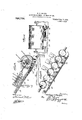
- FIG. 1 is a side elevation of a machine, embodying the present invention.
- FIG. 2 is a detail view in elevation of a portion of the opposite side to that shown in Fig. l, and illustrating more particularly the solder applyingmechanism.
- Fig. 3 is a planvi'ew of the lower portion ot the machine.
- Fig.u 4 is a longitudinal sectional view on an enlarged scale showing the magnets.
- Fig. 5 is a transverse sectional view of the runway and a can thereon, taken through the can and through one ofthe magnets.
- Fig. 6 is a detail cross sectional view 'through the soldering mechanism.
- Fig. 1 is a side elevation of a machine, embodying the present invention.
- Fig. 2 is a detail view in elevation of a portion of the opposite side to that shown in Fig. l, and illustrating more particularly the solder applyingmechanism.
- Fig. 3 is a planvi'ew of the lower portion
- FIG. 7 is a perspective view of one of the soldering irons.
- Fig. A8 is a sectional view through one ot the solder feeding devices.
- Fig. 9 is a side elevation of a modified torni of ruiiuf'ay, wherein a inagnetized bai' is used as a tractor.
- Fig. l0 is alongitudinal transverse sectional view, similar to Fig. 5, showing a modified form of the magnet.
- a suitable supporting ira-nie l2 is employed that may be or' any character, and mounted thereupon, is an inclined track or runway comprising Fig. 11 is av spaced rails 13, which as shown, are formed of T-iron, though they may be constructed in any suitable manner.
- Guard rails 14 are also provided, the track and guard rails being carried by brackets 15. Any suitable mea-xs may be employed for delivering cans to t upper end of the track or runway.
- said means is in the form of an elevator belt 16 that operates around a pulley 17 and has blades 18 that support the cans and carry them upwardly.
- the lower portion of the track or runway is twisted, as illustrated at 19, and associated with said lower portiony is means for 'governing the speed of the cans rolling down the inclined track or runway, said means in the present embodiment, consisting of a vertically disposed wheel 2O having a ielding tire 21 that projects beyond the si e of said wheel as shown in Fig. 3.
- This wheel is'carried by a shaft 22 journaled on suitable bearings in a bracket frame 23, and said shaft is driven by any suitable means, as for instance, a belt 24 o erating around a pulley 25 liXed to the shaft.
- a gas supply pipe 28 is connected to the pipe 26 as is also an air supply pipe 29, the assage of gas and air through said pipes ⁇ eing respectively conn -trolled by valves v3() located therein.
- soldering mechanism Associated with the track or runway and ar ranged above the wheel 20 is soldering mechanism. Thile this mechanism may be of any desired type well known to the art, the following mechanism is preferably employed.
- a supporting bar 31 is located above the track, and depending therefrom, are sets of guide rods 32.
- Soldering irons in the form of comparatively light plates 33 of steel or other metal, have ears 34 slidably engaged 45..,with said rods, the vertical rise and fall ⁇ movement of the irons, caused by the passage of a can beneath the iron and to compensate for variationsV in the dia-meters. of cans being limited by stops 35, shown more particularly in Fig. 6.
- the lower ends of these soldering irons are rounded so as to be raised and lowered by contact with the rounded periphery of the can, as shown at 37 and operate upon the cans adjacent to the seams to be soldered XVhile three soldering irons are illustrated in the present embodiment, it is to be understood that any number may be employed, according tothe diameter of the cans operated upon. Solder is fed to the irons from suitable spools 38,
- solder being in the form ⁇ of wires 39,'
- soldering irons are heated by means of burners 45 that project the flames against the opposite sides of said irons to those engaged by the solder wires' and said burners are supplied by gas and air pipes 4G and 47 controlled by suitable valves 48.
- this magnetic field ⁇ is produced by a series of horse-shoe magnets 4f) located between the rails 13, said series extending longitudinally thereof.
- the poles of the magnets are located 'adjacent to or in actual contact with the cans.
- These magnets may be disposed in any desiredl relation, but in the structure illustrated, they are arranged between suitable insulating and non-magnetic strips and are held in place by the inner ends of the brackets 15.
- the manner in which the machine operates is substantially as follows:
- the elevator 16 carries the cans to be operated upon, to the upper end of the track or runway, and said track or runway is filled with lthe same. If now the wheel 20 is being rotated, it will be evident that the tire 21 thereof engaging the cans at the lower portion of the row of cans will determine the speed of said cans down the track or runway. Moreover as will be evident by reference to Figs. 1 and 3, said wheel will hold the cans against the twisted portion of thel track or runway, thus up-ending them prior to their discharge froml the track or runway.
- the usual cooling belt 5l is employed that operates through -a tank l52 of liquid, the end of the belt being located beneath theend of tli ⁇ e runway.
- the track 'orrunway may vbe disposed at any desired angle of inclination, and the force of the magnetic ield varied accordingly.- rhus if a very steep track lor runway Vis employed more magnetic force is necessarythan W en the track or runway is a very 4slight degree'of inclination.
- solder applying-mechanism While any Well known form of solder applying-mechanism can be successfully employed, that disclosed has certain. advantages.
- the rounded lower edges of the soldering irons insure not only the proper application of the solder, but Wipe it along each can for a con,- siderable distance, a series of said irons being preferably employed in order thattoo much solder does not have to be delivered to one', which would tend to bind-against it and prevent its highly successfuloperation. The.
- movement of the irons is also desirable inasgnuchnas the surface against which the solder'engages is thus consecpientlyr changingp which insures better melting.
- each soldering iron operati Any suitable means may be ein-- Another embodiment of the invention is disclosed in Figs. 9, l0 and 11 and said embodiment includes a number of important features.
- the track or runway, desi nated is substantially the same as that a ready described, the same delivering to a,v cooling belt 54, the movement of the cans dovvn theV same being governed by a Wheel 55, as in the 'first described embodiment.
- mechanism 56 and the solder feeding means 57 correspond to that first described, as does also the heater pipe 58.
- electro-magnets are employed for producing the magnetic field.
- a magnet bar 59 islocated longitudinally-between the tracks, being supported byV non-magnetic posts 60.
- One of the track rails designated 61., is also supported fon non-magnetic material 62. Interposed between this rail and the bar 59 are electro-magnets G3, the poles of which are secured thereto by fasteners 64 of magneticv material.
- the rail (3l and bar 59 will be niagnetized, and consequently the cans will be strongly held against the same.
- the magnets may be energized from any suitable source of electricity.
- one of the rails of the track constitutes a portion of the ,nagnet while the other rail acts yas aguar ivvhich prevents to some extent the heattraveling to said magnet, and injuring or destroying.
- the electromagnets as illustrated in Fig. 10, are disposed at suitable intervals 'sutiicient to insure the proper rolling ofthe cans, and may be located closer together at the soldering mechanism in order to produce a more powerful action at the places Wheresaid soldering mechanism tends .to resist the rotation of the cans. ⁇
- a 7 In mechanism of the character set iorth, the combination with a track or runway against which the cans roll, of soldering mechanism associated with said track or runway, and a plurality of electro-magnets having poles connected to the track or runway for magnetizing the same.
- the combination with a track or runway against which the cans roll said track or runway comprising spaced rails, of a magnet bar extending longitudinally between the rails, and 'electro-magnets connecting one of the rails and the bar, and soldering mechanism associated with said track or runway.
- the combination with a downwardlyinclined track or runway for the cans of longitudinally xed soldering means associated with the track or runway beneath which said cans roll and with which they contact, means at the bottom of said track or runway for governing the speed of the cans, and means associated with the inclined track for compelling -a rolling Contact of said cans with the track beneath.
- a downwardly-inclined track or runway for the cans means located at the lower end of the track or runway for governing the passage of cans down the same,'a soldering means associated with the inclined portion of the track above the governing means, can heating mechanism located on the inclined portion of the -track above the governing means, and means for compelling a rolling contact of the cans with the inclined runway or track.
- a downwardly-inclined track or runway down which the cans roll by Gravity a rotatable can-engaging wheel at the lower end of said track orJ runway for governinoP the speed of the cans down the.track, and mechanism located above the @aegee governor wheel upon the inclined portion of theJ track for acting upon the periphery of said cans.
- a downwardly-inclined track or runway down which the cans roll by gravity a rotary can-engaging wheel located at the lower end of the track or runway for governing the passage of said'cans down thereon, a rotarysolder-teeding mechanism associated with the track above the governing wheel, and a shaft operated by the 'overning wheel and ,controlling the rate o movement of the solder-feeding mechanism.
- an inclined track or runway the npper portion of which is transversely horizontal, the lower portion of which is gradu- '65 ally twisted to cause the cans to tilt to a veror runway for governing the'inovement of or runway for governing the passage of said tical position, means for holding the cans l against the lower twisted portion and governing the speed of ⁇ their passage down the finclined track or runway, and. soldering means for the cans-associated with the track or runway above'said governing means and at a portion of the track wherein thel cans are brought to a position between the horizontal and the vertical.
- soldering mechanism may be opcasioned by said soldering mechanism.
- the combination with a track or runway against which the cans may roll of heating means located at an intermediate portion of the track or runway, and soldering means located at a point on the track in rear of the heating means, said track or runway having that portion of it associated with the can heating means transversely level, and having that portion of it associated with the soldering mechanism disposed at an angle which will bring the end of the can being soldered below the other end of the can.
- a track or runway adapted toA support a can transversely and allow the-latter to have rolling contact therewith, means for moving the can along the track, and means for exerting a magnetic attractive force to draw the can into closer adhesion with the track or runway and compel a rolling contact therewith.
- the combination with a track or run- 'way adapted to support a can transversely and allow the latter to have rolling contact therewith of mechanism for operating on the peripher f of the can located adjacent to the track, and means for exerting a magnetic attractive force to draw the can into closer adhesion with the track and insure its rolling contact with the track.
- a magnetized track or runway adaptedvto support cans transversely and dire7 them to roll there-along.
- the combination withV a track or run- IOC therewith, means for 4exerting a magneticV Way adapted to support a4 can transversely nml allow it t0 haverollmg conf/act therewith, of a pluralityof electro-magnets,having poles connected to the track 0r runway for magnetizing the Same.
- Vset Y fortlna track adapteflto support a can transversely and allw itA lo have rolling Contact aftractive force beneath the Wholefextent .of Sind Itrack or'runwuy' t'o increase the adhesion ofl the can-'thereto but not prevent. the movement of the cans there-along.
Landscapes
- Engineering & Computer Science (AREA)
- Mechanical Engineering (AREA)
- Electric Connection Of Electric Components To Printed Circuits (AREA)
Description
W. J. PHELPS. MEANS PoR SOLDERING END sEAMs 0F cANs. APPLIOATION FILED MAB. 21, 190B.
4 SHEETS-SHEET l Patented Jan. 18, 1910.
W. J. PHELPS. MEANS POR SOLDBRING END SEAMS 0I GANS. I APPLICATION FILLED MAR.21, 1908. 946,733. Patented Jan; v18, 1910.
4 SHMTSSHBBT 2.
Walz-erazem, 3mm@ alfrozum W. J. PHELPS. MEANS FOR SOLDERING END SEAMS yQF GANS. APPLIUATION FLED M43. 21, '1908.
Patented Jan 18,1910.
4 SHEETS-SHEET 3 W. J. PHELPS. MEANS PoR SOLDBRING END sEAMsoP GANS.
APPLICATION FILED 16.13.21, 1908.
Patented Jan. 18, 11910.
4 SHEETS-SHEET 4.
i To all whom 'fit may concern:
- creasing cans and vertically rise and fall so asV to vbe properly applied to the end seams.
Iyet from various causes priorto my invention, the cans were liable to slip or slide simple, inexpensive and eiective character said trackA or runway.
mechanical devices` for moving the cans Chl.
WALTER a. rHELrs, or BALTIMORE, MARYLAND, Assieivor. 'ro AMERICAN CAN i COMPANY, or NEW aromi, 1v. Y., A oonronArIoN or NEW JERSEY.
' MEANS roe seminativo yErw sEAr/Isfor oANs.
' Applicatonled March 21,
Be it known that I, WALTER J. PHELrs, a citizen of the United States, residingl at Baltimore, in the State of Maryland, avel invented a new and useful Means for Soldering End Seams of Cans, of. whielithe following is a specification.
This invention relates to means for-,soldering the heads Aof cans t0 the bodies thereof, and more particularly to that class of machines known generally' to the trade as oaters. In the machine of this character now ing general use, a horizontal track or4 runway is employed, over which'` the cans are rolled by an'endless chain, paddles, prol jections, or other analogous devices, the cans being carried past the heating yand solder applying means. The continuous rolling of' cans is essentialtothe proper soldering operation -in order thatsaid cans lmay be uni- `formly heated at the seam along their entire circumferencey in order that the solder may While a continuous rollingy of the cans is absolutely essential, as already explained,
upon' the track or runway. n One of the primary objects of the present` invention is to rovide novel means of aV for insuring the rolling of the cans by intheir adhesion to the track or run Way, without, however, imparting any ina-l terial` resistance to their movement along` A further object is to provide a machine in which the necessity of chains or other alon the track or runway is eliminated, gravity being employed .in lieu thereof.
Still another object is to provide novel but simple and effective means for applying the solder to the cans, said means being very economioal'in the use of solder. And providing a can soldering mechanism in which the soldering irons automatically adjust themselves to variations indiaineter of the follow and contact witheach can as itpasses beneath the irons, and in this connection a further yobject is :to provide means whereby Speccation of Letters Eatent.
.sectional view therethrough.
meenten aan. is, ieio.
ieee. sensi no. 42e-,481. v
the' rate of delivery of cans passing down `the chute may be controlled, and whereby the feed of solder to the soldering irons may be regulated in accordance with the feed of the cans.
.A further object of the invention is to provide a machine having therein a novel arrangement ot track structure or vrunway which is twisted in such' a mannerthat the cans passing thereover, will, during the heatingoperatioii, be disposed about transversely Y horizontal in order to betterl confine the heat to the ends tobe soldered, the said track or runway from thebeginning of the soldering operation to the ejecting mechanism at the bottom of the track being transversely twisted so Aas to'tilt the cans and assist them in assuniing an upright position in order to insure the solder` settling down in the joints and' to'secure the proper cooling or setting of the soldered joints.
In the accompanying drawii1gs:-%Figure l is a side elevation of a machine, embodying the present invention. Fig. 2 is a detail view in elevation of a portion of the opposite side to that shown in Fig. l, and illustrating more particularly the solder applyingmechanism. Fig. 3 is a planvi'ew of the lower portion ot the machine. Fig.u 4 is a longitudinal sectional view on an enlarged scale showing the magnets. Fig. 5 is a transverse sectional view of the runway and a can thereon, taken through the can and through one ofthe magnets.' Fig. 6 is a detail cross sectional view 'through the soldering mechanism. Fig. 7 is a perspective view of one of the soldering irons. Fig. A8 is a sectional view through one ot the solder feeding devices. Fig. 9 is a side elevation of a modified torni of ruiiuf'ay, wherein a inagnetized bai' is used as a tractor. Fig. l0 is alongitudinal transverse sectional view, similar to Fig. 5, showing a modified form of the magnet.
Similar reference numerals designate corresponding. parts in all the liguresof the drawings.
Referring iist to the embodiment disclosed, in ligs. l-S inclusive, a suitable supporting ira-nie l2 is employed that may be or' any character, and mounted thereupon, is an inclined track or runway comprising Fig. 11 is av spaced rails 13, which as shown, are formed of T-iron, though they may be constructed in any suitable manner. Guard rails 14 are also provided, the track and guard rails being carried by brackets 15. Any suitable mea-xs may be employed for delivering cans to t upper end of the track or runway. In the present embodiment, said means is in the form of an elevator belt 16 that operates around a pulley 17 and has blades 18 that support the cans and carry them upwardly.`
In the present embodiment, the lower portion of the track or runway is twisted, as illustrated at 19, and associated with said lower portiony is means for 'governing the speed of the cans rolling down the inclined track or runway, said means in the present embodiment, consisting of a vertically disposed wheel 2O having a ielding tire 21 that projects beyond the si e of said wheel as shown in Fig. 3. This wheel is'carried by a shaft 22 journaled on suitable bearings in a bracket frame 23, and said shaft is driven by any suitable means, as for instance, a belt 24 o erating around a pulley 25 liXed to the shaft.
Extending alongside one of'the rails 13 of the run way or .track is a burner pipe 26 having a series of discharge orifices 27 in its upper side. A gas supply pipe 28 is connected to the pipe 26 as is also an air supply pipe 29, the assage of gas and air through said pipes `eing respectively conn -trolled by valves v3() located therein. Associated with the track or runway and ar ranged above the wheel 20 is soldering mechanism. Thile this mechanism may be of any desired type well known to the art, the following mechanism is preferably employed. A supporting bar 31 is located above the track, and depending therefrom, are sets of guide rods 32. Soldering irons, in the form of comparatively light plates 33 of steel or other metal, have ears 34 slidably engaged 45..,with said rods, the vertical rise and fall `movement of the irons, caused by the passage of a can beneath the iron and to compensate for variationsV in the dia-meters. of cans being limited by stops 35, shown more particularly in Fig. 6. The lower ends of these soldering irons are rounded so as to be raised and lowered by contact with the rounded periphery of the can, as shown at 37 and operate upon the cans adjacent to the seams to be soldered XVhile three soldering irons are illustrated in the present embodiment, it is to be understood that any number may be employed, according tothe diameter of the cans operated upon. Solder is fed to the irons from suitable spools 38,
said solder being in the form `of wires 39,'
which are delivered from said spools between feeding rolls 40. Certain of the rolls 40 are carried by a shaft 41, which is geared illustrated at 42 to the shaft 22, and
'tubes 43 which direct the ends of the solder against the lower portion of the soldering irons 33, said portions being preferably provided with vertical channels 44 in which the ends of the solder wires are located. The soldering irons are heated by means of burners 45 that project the flames against the opposite sides of said irons to those engaged by the solder wires' and said burners are supplied by gas and air pipes 4G and 47 controlled by suitable valves 48.
It will be evident that in this machine, the movement of the cans is effected by gravity, but inasmuch as said cans are comparatively light and ordinarily roll against one another, there is liability of their slipping. To prevent this and insure their rolling, a magnetic field is established which holds the cans firmly against the runway or track, thus securing greater adhesion and in suring the necessary rolling action. In the embodiment of the invention now being con sidered, this magnetic field `is produced by a series of horse-shoe magnets 4f) located between the rails 13, said series extending longitudinally thereof. The poles of the magnets are located 'adjacent to or in actual contact with the cans. These magnets may be disposed in any desiredl relation, but in the structure illustrated, they are arranged between suitable insulating and non-magnetic strips and are held in place by the inner ends of the brackets 15.
The manner in which the machine operates, is substantially as follows: The elevator 16 carries the cans to be operated upon, to the upper end of the track or runway, and said track or runway is filled with lthe same. If now the wheel 20 is being rotated, it will be evident that the tire 21 thereof engaging the cans at the lower portion of the row of cans will determine the speed of said cans down the track or runway. Moreover as will be evident by reference to Figs. 1 and 3, said wheel will hold the cans against the twisted portion of thel track or runway, thus up-ending them prior to their discharge froml the track or runway. As the cans roll down from the upper portion of said track or runway, they enter the magnetic field produced by the magnets, and they will therefore be drawn firmly against the rails 13, producing suflicii t adhesion to insure their rolling action without resisting their downward movement. That this is true will be evident from the fact that the magnets on either side of each can are pulling with the same force, and consequently there is no tendency of' the cans to stick or hold back at any point. The ends to be soldered of the rolling cans pass over the burners, and are therefore thoroughly heated on all sides. ends successively engage the soldering irons, and the solder delivered thereto will be ap- These heatedv Wheel.
stares ing upon a different portion of the can. After passing said irons, the cans are turned upon end when engaged by the tire 2l of the ployed for removing the cans. Thus in the present embodiment, the usual cooling belt 5l is employed that operates through -a tank l52 of liquid, the end of the belt being located beneath theend of tli`e runway.
There are a number of advantages for lthis g structure. ln the first place, chai-ns or other devices for fmoving the cans are dispensed with, and each can isv individually held against the track so that it will revolve. The speed ofthe can is determined by the speed of :the Wheel VJ2O, land kthis automatioally ydetermines. the feed 'ofthe solder, the solder feeding means being lgeared to said wheelas above described. it will of course bc understood that 'the track 'orrunway may vbe disposed at any desired angle of inclination, and the force of the magnetic ield varied accordingly.- rhus if a very steep track lor runway Vis employed more magnetic force is necessarythan W en the track or runway is a very 4slight degree'of inclination.
Moreover the. particular arrangement of the track, vso far as the twisting thereof, etc. is concernsdpis not' vitally important, though thearrangement disclosed is preferred for the reason lthat the cans are held substantially ievel or horizontal during the heating operation, and are then tilted to theproper angle for the soldering operation. After the solder has been applied, they are quickly brought to' u' right positions, While the soly Ider is still mo ten so as to insure proper cooling or setting of the joints. it will be evident that by this arrangement, during the heating operation, the heat is more nearly 'confined to the -ends 'of the cans, as it will not as readily travel along the cans wouldbe the case if said cans Were tilted. At the same time, it is to be understood that the above described tilting operation or twisting of the track is by no means essential, and.
that the other features of the invention will o aerate nearly as Well if the cans are held in ltilted relation :during their entire travel.-
Whileany Well known form of solder applying-mechanism can be successfully employed, that disclosed has certain. advantages. The rounded lower edges of the soldering irons insure not only the proper application of the solder, but Wipe it along each can for a con,- siderable distance, a series of said irons being preferably employed in order thattoo much solder does not have to be delivered to one', which Would tend to bind-against it and prevent its highly successfuloperation. The.
. movement of the irons is also desirable inasgnuchnas the surface against which the solder'engages is thus consecpientlyr changingp which insures better melting.
each soldering iron operati Any suitable means may be ein-- Another embodiment of the invention is disclosed in Figs. 9, l0 and 11 and said embodiment includes a number of important features.' The track or runway, desi nated is substantially the same as that a ready described, the same delivering to a,v cooling belt 54, the movement of the cans dovvn theV same being governed by a Wheel 55, as in the 'first described embodiment. mechanism 56 and the solder feeding means 57 correspond to that first described, as does also the heater pipe 58.' in this embodiment of the invention, however, electro-magnets are employed for producing the magnetic field. To this end, a magnet bar 59 islocated longitudinally-between the tracks, being supported byV non-magnetic posts 60. 'One of the track rails, designated 61., is also supported fon non-magnetic material 62. Interposed between this rail and the bar 59 are electro-magnets G3, the poles of which are secured thereto by fasteners 64 of magneticv material. `With this embodiment of the invention, it will be noted that the rail (3l and bar 59 will be niagnetized, and consequently the cans will be strongly held against the same. The magnets may be energized from any suitable source of electricity. In this embodiment' therefore one of the rails of the track constitutes a portion of the ,nagnet while the other rail acts yas aguar ivvhich prevents to some extent the heattraveling to said magnet, and injuring or destroying. the insulation of the spools. vThe electromagnets, as illustrated in Fig. 10, are disposed at suitable intervals 'sutiicient to insure the proper rolling ofthe cans, and may be located closer together at the soldering mechanism in order to produce a more powerful action at the places Wheresaid soldering mechanism tends .to resist the rotation of the cans.`
While in this application I have shown a runWa along yifhich cans are rolled by gravity an to which they are held by magnetic traction,`i isA obvious that l' might use in conjunction with sueh magnetic tractive means `a positive means for moving the cans along a runway, such means being shown in my companion application, Serial No. 434,345, filed May a2, isos,
- From the foregoing, it is thought that the construction, operation and many advantages of the herein described invention will be apparentto those skilled in the art.A without further description, and it will be understood that various changes in the size, shape, proportion, and minor details of construction, niay be'resorted to without departing from the advantages of the invent-ion.A Moreover insofar as the utility .of the invention is concerned, Y the mechanism candoe employed for other purposes lof an analogous nature, as torinstance in feeding cans to firming appa- The soldering 4 spirit or sacrificing any of the rio ratas, also in can drying mechanism and in can labeling machines.
Having thus t'ully described .my invention, what I claim as new, and desire to secure by Letters Patent is 1. In mechanism of the character set forth, the combination with a track or runway against which the cans roll, of soldering mechanism associated therewith, and means for producing a magnetic eld in the path ot' movement of the cans operating against the track or runway to increase their adhesion to the track or runway and thereby insure their rolling thereagainst.
2. In mechanism of the character set forth, the combination with a track or runway against which the cans roll, of soldering mechanism associated therewith, and magnetic means for attracting the cans to the track or runway, to increase their adhesion against the same and insure their rollmg.
3. In mechanism of the character Set forth, the con'ibination with a track or runway against which the cans roll, of soldering mechanism associated therewith, and a magnet associated with the track or runway for attracting the cans thereto and increasing their adhesion against the same to insure their rolling.
i. In mechanism of the character set forth, the combination with a track or runway against. which the cans roll, of soldering mechanism associated therewith, and an electro-magnet associated with the track or runway tor attracting the cans thereto and increasing their adhesion against the same to insure their rolling.
5. In mechanism of the character set forth, the combination with a magnetized track or runway against which the cans roll, of soldering mechanism associated with said track or runway.
(S. In mechanism of the character set torth, the combination with a track or runway against. which the cans roll, of soldering mechanism associated therewith, and a magnet connected to the track for magnetizing the same to increase the adhesion of the cans against said track and insure their rolling thereagainst. a
A 7. In mechanism of the character set iorth, the combination with a track or runway against which the cans roll, of soldering mechanism associated with said track or runway, and a plurality of electro-magnets having poles connected to the track or runway for magnetizing the same.
In mechanism-pf the character set forth, the combination with a track or runway against which cans roll, of soldering mechanism associated with said track or runway, a magnet extending longitudinally of the track andhaving its field extending into the path of movement of the cans passing thereover to increase the adhesion of said cans to said track or runway and insure their rolling action.
9. In mechanism of the character set forth, the combination with a track-or runway against which the cans roll, of soldering mechanism associated with said track or runway, a magnet bar extending longitudinally ot the track or runway, and a plurality of electro-magnets connected to the bar;
10. In mechanism of the character set forth, the combination with a track or runway against which the cans roll, said track or runway comprising spaced rails, of a magnet bar extending longitudinally between the rails, and 'electro-magnets connecting one of the rails and the bar, and soldering mechanism associated with said track or runway.
11. In a mechanism of the character set forth, the combination with a downwardlyinclined track or runway for the cans, of longitudinally xed soldering means associated with the track or runway beneath which said cans roll and with which they contact, means at the bottom of said track or runway for governing the speed of the cans, and means associated with the inclined track for compelling -a rolling Contact of said cans with the track beneath.
12. In a mechanism of the character set forth, a downwardly-inclined track or runway for the cans, means located at the lower end of the track or runway for governing the passage of cans down the same,'a soldering means associated with the inclined portion of the track above the governing means, can heating mechanism located on the inclined portion of the -track above the governing means, and means for compelling a rolling contact of the cans with the inclined runway or track.
13. In a mechanism of the character set forth, the combination with a downwardlyinclined track or runway down which the cans roll, of rotary can-governing means located at 4the lower end of the inclined track or runway forgoverning the passage of said cans down thereon, soldering means for the cans associated Vwith the track or runway and located above said governing means, can-heating means associated with the inclined' portion of the track above the governing means, and means for compelling a rotation of the cans as they pass the heating and soldering means.
14. In a mechanism for treating the lperiphery of cans, a downwardly-inclined track or runway down which the cans roll by Gravity, a rotatable can-engaging wheel at the lower end of said track orJ runway for governinoP the speed of the cans down the.track, and mechanism located above the @aegee governor wheel upon the inclined portion of theJ track for acting upon the periphery of said cans. l
"15. In a mechanism fortreating the peripliery of cans, a downwardly -inclined track or runway down which the cans roll by gravity, soldering means Jfor the cans associated with the track `or runway, and
mechanism on a lower portion ot the track thecans down the track or runway, said mechanism controlling the feed of solder to the soldering means.
16. In A'mechanism of the character set forth, the combination with la downwardly inclined track or runway for the cans, ot a rotary can en 'aging wheel located at the lower end of t e trackV or runway' for governing the passage of said cans down said track vor runway, means for rotating the wheel, and soldering means for the cans associated with the track or runway and located above the governing means.
17. In a mechanism of the character set forth, a downwardly-inclined track or runway down which the cans roll by gravity, a rotary can-engaging wheel located at the lower end of the track or runway for governing the passage of said'cans down thereon, a rotarysolder-teeding mechanism associated with the track above the governing wheel, and a shaft operated by the 'overning wheel and ,controlling the rate o movement of the solder-feeding mechanism.
18. In a mechanism of the characterv set forth, the combination with a downwardly` inclined track or runway down which the cans roll by gravity, of a,1 rotary can-engaging o wheel located at the lower end of the track 4 cans. down thereon, a soldering mechanism located upon the inclined portion of thev cans down the track or runway, means forv rotating the wheel, and soldering means for the heads of the cans associated with thei track or runway and located above the wheel.
20. Ina mechanism of the character set forth, an inclined track or runway, the npper portion of which is transversely horizontal, the lower portion of which is gradu- '65 ally twisted to cause the cans to tilt to a veror runway for governing the'inovement of or runway for governing the passage of said tical position, means for holding the cans l against the lower twisted portion and governing the speed of` their passage down the finclined track or runway, and. soldering means for the cans-associated with the track or runway above'said governing means and at a portion of the track wherein thel cans are brought to a position between the horizontal and the vertical.
2l. In mechanism` of the character set forth, the combination with a track or runway down which the cans gravitate ainl/ against which they roll, of magnetic means for attracting the cans toward said track or runway to increase their adhesion and insure their rolling thereagainst, and solder- Aing means associated with said.. track or runway andv operating on the cans that roll thereagainst.
22. In mechanism of the character set forth, the combination with an inclined track or runway down' which the cans gravil tate, and against which they roll, of magnetic means for attracting thecans toward said track or runway to increase their adhesion and insure their rolling thereagainst, means located at the lower portionv of the track or runway for governing their movement down the same, and soldering means associated with said tracker runway and operating on the cans that roll thereagainst.
'23. In mechanism of the character set forth, the combination with an inclined track or runway down which the cans gravitate and against which they roll, of magnetic means for attracting the cans toward said track or runway to increase their adhesion and insure their rolling thereagainst, meansv located at the lower portion of the track or runway for governing their movement down the same, soldering means associated with said track or runway and operating on the cans that roll thereagainst, said f soldering means being located above the governing means, and can heating means lo- 24. In mechanism of the character set forth, the-combination with a track or run-l way along which the cans roll, of soldering mechanism associated with said track. or
runway, and magnetic means for attracting against,the number'of magnets being increased 4at the soldering mechanism to overcome any resistance to the rolling action that '130 11o'l` lcated longitudinally 'of the track or runway.
izo
may be opcasioned by said soldering mechanism.
26. In a mechanism of the character set forth, the combination with a track or runway with which the cans Contact to produce a rolling motion thereof, of a guide located contiguous to the `track or runway, a soldering iron freely movable vertically on said guide with which iron said cans contact in their downward passage, and means for heating the iron and feedingV solder againstthe same. f
27. In a mechanism of the character set forth, the combination of a track or runway along which the cans roll, spaced vertical guide rods located contiguous to the track or runway, a soldering iron lixed in its longitudinal -position, but freely movable vertically on said guide rods, and means for feeding solder to the iron between the rods.
Q8. In a mechanism of the characterset forth, the combination with a track or runway along which the cans roll, of a support located contiguous to the track or runway, a longitudinally-fixed soldering iron mounted on the support for free up-and-down movement and having a conveXly-rounded lower edge that engages the can.
. 29. In a mechanism of the character set forth, the combination with an inclined track or runway down which the cans gravitate and against which they roll, of means at the lower end of. the track or runway for governing the movement of the cans down the same, a support associated with therunway above the governing means, a series of sets of spaced guides mounted on the support, a series of independent soldering irons, each slidably mounted on one pair of said guides and having rounded lower ends, said irons successively contacting with and engaging the cans passing thereunder, means for heating the irons, and heating means'for the cans located on the track or runway in advance of the soldering irons.
30. In a mechanism of the character set forth, the combination with a track or runway against which the cans may roll, of heating means located at an intermediate portion of the track or runway, and soldering means located at a point on the track in rear of the heating means, said track or runway having that portion of it associated with the can heating means transversely level, and having that portion of it associated with the soldering mechanism disposed at an angle which will bring the end of the can being soldered below the other end of the can. y
3l. In a mechanism ofthe character set forth, the combination with can heating means and soldering mechanism,- of a track or runway 'over which the cans roll by gravity, said track or runway havingthe portion associated with the heating means disposed so as to be transversely horizontal, having the portion associated with the soldering mechanism transversely twisted with respect to the first-named portion and having the portion below the soldering means twistedso that the cans are brought to a vertical cooling position.
32. In a mechanism of the character set forth, the combination with a track or runway adapted t0 support a can transversely and allow it to have rolling contact therewith, of means for creating a field of magnetism in which said cans move to effect their rolling contact against'the track or runway.
In a mechanism of the character set forth, the combination with a track or runway adapted to support a can transversely and allow it to have rolling contact therewith, of means for producmg a magnetic field in the ath of movement of the cans to increase their adhesion to the track or runway and thereby compel their-rolling contact therewith. y
34. In a mechanism of the character set forth, a track or runway adapted toA support a can transversely and allow the-latter to have rolling contact therewith, means for moving the can along the track, and means for exerting a magnetic attractive force to draw the can into closer adhesion with the track or runway and compel a rolling contact therewith.
35. In a mechanism of the character set forth, the combination with a track or run- 'way adapted to support a can transversely and allow the latter to have rolling contact therewith, of mechanism for operating on the peripher f of the can located adjacent to the track, and means for exerting a magnetic attractive force to draw the can into closer adhesion with the track and insure its rolling contact with the track.
3G. In a mechanism of the character vset forth, a track adapted to support a can transversely and allow it to have rolling contact therewith, of means for exerting a magnetic attraction beneath said track or runway to increase the adhesion of the cans thereto but not 'prevent the rotation of the cams there-a|` ong.
3T. In a mechanism of the character set forth, the combination with a` track or runway adapted to support a can transversely and allow it to roll there-along, of an electromagnet associated with the track or runway for attracting the cans thereto and increasing their adhesion against the same to insure la rolling contact therewith.
38. In a mechanismv of the character set forth, a magnetized track or runway adaptedvto support cans transversely and alles7 them to roll there-along. 39. In a mechanism of the character set forth, the combination withV a track or run- IOC therewith, means for 4exerting a magneticV Way adapted to support a4 can transversely nml allow it t0 haverollmg conf/act therewith, of a pluralityof electro-magnets,having poles connected to the track 0r runway for magnetizing the Same.
40, In n mechanism of 'the character Vset Y fortlna track adapteflto support a can transversely and allw itA lo have rolling Contact aftractive force beneath the Wholefextent .of sind Itrack or'runwuy' t'o increase the adhesion ofl the can-'thereto but not prevent. the movement of the cans there-along. i
A 41; inA a mechanism of the charcter setforth, the combination withv a downwardly inclined track or. runway for thecanQmeans at thcfbottom of said track for governing the epecd of the cans, and magnetic means asso- ,cans rnll by gravity, the discharge crd of `che ,track being twisted of nrotary cuil-,-ngaging wheel located atftie (lrfchargeerd of the vtrack lor governing' the )menge ct' the cans down the track :1S-Well as |1penfl'irg the-cmu In itestimony, th' I claim tlif foregoing as my own, 'I have lneret affixed my Signav ture 1n the presence r )f-tv'o witnesses Vuf'itnesses: I
' J OHN H.. SIGG] Rs, FANNIE VVA'GNMR.
Priority Applications (1)
| Application Number | Priority Date | Filing Date | Title |
|---|---|---|---|
| US42248108A US946733A (en) | 1908-03-21 | 1908-03-21 | Means for soldering end seams of cans. |
Applications Claiming Priority (1)
| Application Number | Priority Date | Filing Date | Title |
|---|---|---|---|
| US42248108A US946733A (en) | 1908-03-21 | 1908-03-21 | Means for soldering end seams of cans. |
Publications (1)
| Publication Number | Publication Date |
|---|---|
| US946733A true US946733A (en) | 1910-01-18 |
Family
ID=3015154
Family Applications (1)
| Application Number | Title | Priority Date | Filing Date |
|---|---|---|---|
| US42248108A Expired - Lifetime US946733A (en) | 1908-03-21 | 1908-03-21 | Means for soldering end seams of cans. |
Country Status (1)
| Country | Link |
|---|---|
| US (1) | US946733A (en) |
Cited By (3)
| Publication number | Priority date | Publication date | Assignee | Title |
|---|---|---|---|---|
| US2525765A (en) * | 1949-04-22 | 1950-10-17 | Norman H Betge | Component feeding device for automatic machines |
| US4136765A (en) * | 1977-06-06 | 1979-01-30 | Western Electric Company, Inc. | Methods of and apparatus for orienting electrically asymmetrical devices with magnetic handling |
| US4670087A (en) * | 1984-08-01 | 1987-06-02 | Brown Packaging Inc. | Labeling machine |
-
1908
- 1908-03-21 US US42248108A patent/US946733A/en not_active Expired - Lifetime
Cited By (3)
| Publication number | Priority date | Publication date | Assignee | Title |
|---|---|---|---|---|
| US2525765A (en) * | 1949-04-22 | 1950-10-17 | Norman H Betge | Component feeding device for automatic machines |
| US4136765A (en) * | 1977-06-06 | 1979-01-30 | Western Electric Company, Inc. | Methods of and apparatus for orienting electrically asymmetrical devices with magnetic handling |
| US4670087A (en) * | 1984-08-01 | 1987-06-02 | Brown Packaging Inc. | Labeling machine |
Similar Documents
| Publication | Publication Date | Title |
|---|---|---|
| GB1021841A (en) | Method and apparatus for supporting glass sheets | |
| US1807312A (en) | Continuous reversible toaster | |
| US1686696A (en) | Heating furnace | |
| US1705703A (en) | Furnace | |
| US1534677A (en) | Can-body-soldering machine | |
| US1466029A (en) | Peeking mechanism | |
| US3071478A (en) | Sterilizing method for canned foodstuffs | |
| US1635406A (en) | Conveyer | |
| US1799465A (en) | Means for automatically soldering the side seams of containers and the like | |
| US1295762A (en) | Pan cleaning and greasing machine. | |
| US2257740A (en) | Method and apparatus for coating articles | |
| US1907013A (en) | Treating apparatus | |
| US1699955A (en) | Material conveyer for furnaces | |
| US1856084A (en) | Method and apparatus for subjecting articles to x-rays | |
| US1932158A (en) | Method and means of applying partial coatings to articles | |
| US1592661A (en) | Heat-treating machine | |
| US1917918A (en) | System of apparatus for galvanizing metal pipes | |
| US249244A (en) | Apparatus for soldering sheet-metal cans | |
| US1473675A (en) | Glazing machine | |
| US2672269A (en) | Container capping machine | |
| DE747867C (en) | Continuous furnace with vibrating beam conveyor | |
| US2035890A (en) | Heat-treating machine | |
| US1367018A (en) | Soldering-machine | |
| US1736248A (en) | Bar-heating furnace | |
| US1319867A (en) | Machine for coating articles |