US1856084A - Method and apparatus for subjecting articles to x-rays - Google Patents
Method and apparatus for subjecting articles to x-rays Download PDFInfo
- Publication number
- US1856084A US1856084A US296980A US29698028A US1856084A US 1856084 A US1856084 A US 1856084A US 296980 A US296980 A US 296980A US 29698028 A US29698028 A US 29698028A US 1856084 A US1856084 A US 1856084A
- Authority
- US
- United States
- Prior art keywords
- tubular member
- articles
- anode
- ray beam
- guideway
- Prior art date
- Legal status (The legal status is an assumption and is not a legal conclusion. Google has not performed a legal analysis and makes no representation as to the accuracy of the status listed.)
- Expired - Lifetime
Links
- 238000000034 method Methods 0.000 title description 6
- 230000000694 effects Effects 0.000 description 3
- 238000001816 cooling Methods 0.000 description 2
- 239000000463 material Substances 0.000 description 2
- 230000001954 sterilising effect Effects 0.000 description 2
- 241000238631 Hexapoda Species 0.000 description 1
- 241000208125 Nicotiana Species 0.000 description 1
- 235000002637 Nicotiana tabacum Nutrition 0.000 description 1
- BFPSDSIWYFKGBC-UHFFFAOYSA-N chlorotrianisene Chemical compound C1=CC(OC)=CC=C1C(Cl)=C(C=1C=CC(OC)=CC=1)C1=CC=C(OC)C=C1 BFPSDSIWYFKGBC-UHFFFAOYSA-N 0.000 description 1
- 239000004020 conductor Substances 0.000 description 1
- 238000010276 construction Methods 0.000 description 1
- 230000006378 damage Effects 0.000 description 1
- 230000003247 decreasing effect Effects 0.000 description 1
- 235000013601 eggs Nutrition 0.000 description 1
- 235000013305 food Nutrition 0.000 description 1
- 238000010438 heat treatment Methods 0.000 description 1
- 239000011810 insulating material Substances 0.000 description 1
- 239000007788 liquid Substances 0.000 description 1
- 238000004519 manufacturing process Methods 0.000 description 1
- 239000002184 metal Substances 0.000 description 1
- 238000005381 potential energy Methods 0.000 description 1
- 230000000284 resting effect Effects 0.000 description 1
- 238000004659 sterilization and disinfection Methods 0.000 description 1
- 239000002699 waste material Substances 0.000 description 1
- XLYOFNOQVPJJNP-UHFFFAOYSA-N water Substances O XLYOFNOQVPJJNP-UHFFFAOYSA-N 0.000 description 1
Images

Classifications
-
- G—PHYSICS
- G01—MEASURING; TESTING
- G01N—INVESTIGATING OR ANALYSING MATERIALS BY DETERMINING THEIR CHEMICAL OR PHYSICAL PROPERTIES
- G01N23/00—Investigating or analysing materials by the use of wave or particle radiation, e.g. X-rays or neutrons, not covered by groups G01N3/00 – G01N17/00, G01N21/00 or G01N22/00
- G01N23/02—Investigating or analysing materials by the use of wave or particle radiation, e.g. X-rays or neutrons, not covered by groups G01N3/00 – G01N17/00, G01N21/00 or G01N22/00 by transmitting the radiation through the material
- G01N23/06—Investigating or analysing materials by the use of wave or particle radiation, e.g. X-rays or neutrons, not covered by groups G01N3/00 – G01N17/00, G01N21/00 or G01N22/00 by transmitting the radiation through the material and measuring the absorption
- G01N23/18—Investigating the presence of flaws defects or foreign matter
Definitions
- One of the objects of this invention is to provide a simple and thoroughly practical method for subjecting articles, such as packaged goods like tobacco, food products, and the like, to X-rays and which will be lnghly e'llicient in practice, capable ct being inexpensively and rapidly carried on, and well adapted tor treatment oi articles on a large scale.
- Another object is to provide an art of the above-mentioned nature whereby a highly ethcient use is made of the energy dissipated in the Il'lLray tube in the production cit Iii-rays. .linother object isto provide simole and thoroughly practical Yuray sterilizing apparatus of inexpensive and durable construction, highly etficient action, and capable of operating at high speed.
- Another object is to provide an apparatus of the abovenientioned nature in which waste cl K-ray gy is minimized and in which the articles i ted are, subjected to the X-rays in which will insure positive results.
- 1i itner objectis to provide an apparatus at the above nature well adapted to meet the conditions of hardpractical use.
- the invention accordingly consists in the 'l eatures cit" conhtruction, combinations of elements, arrangements of parts and in the several steps and relation and order of each oil the same to one or more of the others as "will be illustratively described herein, and the scope ol the application o'li which will be indicated in the following claims.
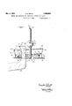
- Figure l is a plan viewof the apparatus;
- Figure 2 is a front elevation partly in vertical sectiomand Application filed August 2, 1928. Serial in. 296,980.
- Figure 3 is an enlarged sectional View taken on the'line 3-3 of Figure 1.
- FIG. 10 an appropriate base or table, adapted to be supported by any suitable standards (not shown) and provided with a substantially centrally positioned opening ll. lln X-ray tube 12, preferably of the hot cathode type, is mounted and insulatingly supported in any suitable manner so that its longitudinal axis extends substantially vertically and centrally through the opening ll in the base 10; the Kerry tube 12 is provided with a filament cathode 13 adapted to be energized from any suitable source oil filament heating energy.
- the X-ray tube 12 has an anode l t positioned refer-ably so that its active :tace extends su stantially transversely to the longitudinal axis of the X-ray tube 12'; accordingily, when the X-ray tube 12 is mount its axis extending vertically, as is clearly shown in Figure 2, the active face oi? the anode 14: extends substantially horizontally and the X-ray beam emanating therefrom will be directed in a general downward direction but throughout. a scope in- F30 eluding substantially to either side of the vertical axis as seen in Figure l.
- the anode 14 may be of the water cooled.
- cooling coils being indicated at 15 and the entry and exit tubes or conduits for the cooling git liquid being indicated-at 16 and 17.
- Any sultable source of high potential energy may be connected across the anode 14 and cathode 13 as by the conductors 16 and v 18, for
- Sup orted u on the base or table 10 is a guideway, the use member of which com prises a tubular member 20 cut away or slotted at its upper portion as indicated at 21 (see also Figure 3), this slot 21-e'xtending preferably'throughout theentire length of the tubular member 20.
- the tubular member 20 is curved about the X-ray tube 12, the curve thereof being given, as is clearly seen in Figure 1, the form of a spiral. Accord-' ingly, the tube 20 extends from apoint 22 tubular member 20 intermediate of the abovementioned points 22 and 23 will thus be seen to be of progressively varying distances from the vertical axis of the X-ray beam.
- the tubular member 20 is preferably also curved in the form of a helix, as is more clearly shown in Figure 2, and this helical curvature is preferably such that the point 23 is at a higher elevation than the point 22. .Aside, therefore, of the progressively closer approach of the tubular member 20 to the vertical axis of the X-ray beam as the path of travel along the member 20 from the point 22 to the point 23 is traversed, there is thus brought about a pro ressive decrease in the vertical distance etween the tubular member 20 and the anode 14 of the X-ray tube. This latter relation is clearly indicated in Figure 1.
- the tubular member 20 forms preferably the bottom member of an appropriate gu'rdeway; coacting with the tubular member 20 and adapted to form lateral guides is a plurality of members spaced laterally and vertically from the tubular member 20.
- two guide members 24 and 25 (see Figure 2) preferably made of a suitable insulating material and supported in vertically spaced relation from each other and from the tubular member 20 and in laterally spaced relation from the tubular member 20 by suitable brackets 26, and appropriate in number.
- the members 24 and 25 are given a spral curvature (see Figure 1) and preferably also a helical curvature commensurate with' the curvatures given the tubular member 20. and preferably the upper guide member 25 is of slightly greater radius than is the lower guide member 24, as is clearly shown in Figure 2.
- This degree of leaning of the packages 27 is preferably such that the major plane of the packages 27 approximates a relation that is substantially normal to the X-rays emanating from the anode 14.
- a flexible conveyor member 28 Resting within the tubular member 20 and held therein by reason of the fact that the slot cut into the member 20 is less than 180 in extent is a flexible conveyor member 28.
- This conveyor member 28 may be in the form of a flexible metal tube or may consist of any appropriate flexible material which may also be non-conducting, if desired.
- the flexible member 28 isexposed throughout the upper portion of the tubular member 20 so that the packages 27 rest directly upon the flexible member 28.
- the flexible member 28 is preferably endless and suitably mounted on the underside of the base or table 10 and adjacent the inner a tube 31 in a forward direction in order to receive therethrough and guide the flexible member 28 to'a pulley 32 suitably mounted at the forward portion of the apparatus.
- the flexible member 28 passes upwardly over the pulley 32 (as viewed in Figure 1) and then passes into the other end 20a of the tubular member 20; the latter, aswill be clearly seen from Figure 1, is extended substantially tangentially in a forward direction from the point 22 hereinbefore mentioned.
- Either or both pulleys 29 and 32 may be positively driven from any suitable source of power; preferably both these pulleys are driven as is diagrammaticallv indicated n F gure 1. and the direction of drive is preferably such that the flexible member 28 is withdrawn from the inner end of the tubular member 20 and enters the outer end 20a of the tubular member 20, the direction of drive being in dcated bv the arrow shown in Figure 1. Preferably there is juxtaposed with respect to the pulley 32 and spring pressed toward the latter. another pulley 33 in order that the endless flexible member 28 may be securely gripped by the pulley 32. Accordinglv.
- the packages 27 are placed upon the tangential portion 20a in the tubular member 20 either by hand or by any suitable mechanical means.
- the packages thus rest upon the flexible moving member 28 and lean against the lateral guides 24 and 25.
- the flexible conveyor mem ber 28 being in movement at an appropriate rate of speed, effects a movement of the succession of packages along the hereinbefore described path provided by the guideway.
- the leaning over of the packages insures their being exposed substantially normally to the X-rays emanating from the anode 14 while the path of movement to which the packages are subjected is such that they are progressively carried inwardly toward the vertical axis of the X-ray beam, due to the substantial spiral curvature of the guideway, and simultaneously, due to the helical curvature of the guideway, the vertical distance between the packages and the anode is progressively decreased.
- a chute 4O diagrammatically shown in Figure 2.
- the intensity of the X-ray beam is not uniform throughout its scope, and that at the same time the package is brought into such close proximity to the anode that such an intense dose of X-rays is directed through the article or material in the package that sterilization thereolt is positively assured.
- the path of travel to which the package or the succession of packages is Sub ected is such that a maximum number of packages may be simultaneously subjected to the available beam of X-rays emanating from the anode, whereby the rate at which the packages or articles are treated is greatly increased over the rate which has heretofore been possible to achieve.
- an X-ray tube mounted with its axis substantiall vertical and having an anode whose active ace extends substantially transversely to said axis, means forming a substantially spiral and helical guideway about the substantiallyvertical axis of said tube and adapted to guide a plurality of articles simultaneously into the beam of-X-rays emanating from said anode and to distribute said articles throughout varying focal distances from said anode, and means for predeterinining the rate of movement of the articles along said guideway.
- an X-ray tube mounted with its axis substantially vertical and having an anode whose active face extends substantially transversely to said axis, means forming a substantially spiral guideway about the substantially vertical axis of said tube and adapted to guide a plurality of articles simultaneously into the beam of X-rays emanating from said anode and to distribute said articles throughout varying focal distances from said anode, and means for predetermining the rate of movement of the articles along said guideway.
- apparatus of the character described in combination, an X-ray tube having the plane of its anode substantially horizontal so as to provide an X-ray beam emanating from said anode of substantially in scope about each side of the substantially vertical axis of said beam, and a traveling conveyor .for carrying articles into said X-ray beam and having a path of, travel that is substantially spiral about the substantially verticalaxis of the X-ray beam.
- an X-ray tube having the plane of its anode substantially horizontal so as to provide an X-ray beam emanating from said anode of substantially 90 in scope about each side of the substantially vertical axis of said beam, and a traveling conveyor for carrying articles into said X-ray beam and having a path of travel that is substantially helical about the substantially vertical axis of the X-ray beam.
- an X-ray tube having the plane of its anode substantially horizontal so as to rovide an X-ray beam emanating from sai anode of substantially 90 in scope about each side of the substantially vertical axis of said beam, and a traveling conveyor for carrying articles into said X-ray beam and havlng a path of travel that is substantially spiral and helical aboutthe substan tially vertical axis of the X-ray beam.
- an X-ray tube mounted to have the plane of its anode substantially horizontal so as to provide an X-ray beam directed downwardly and laterally, a guideway associated with said X-ray tube and curved about the vertical axis of the X-ray beam,
- said guideway including a curved tubular member having a slot extending substantially throughout its length, and movable flexible means in said tubular. member, exposed through said slot, and adapted to engage and move an article along said guideway.
- an X-ray tube mounted to have the plane of its anode substantially horizontal so as to provide an X-ray beam directed downwardly and laterally, a guideway for guiding an article into the X-ray beam, said guideway including a tubular member curved spirally about substantially the vertical axis of the X-ray beam, said tubular member having a slot therein substantially throughout its length, and movable flexible means in said tubular member and exposed through said slot for engaging .and moving an article along said guideway.
- an X-ray tube mounted to have the plane of its anode substantially horizontal so as to provide an X-ray beam directed downwardly and laterally, a guideway for guiding an article into the X-ray beam, said guideway including a tubular member curved helically about substantially the vertical axis of the X-ray beam, said tubular member having a slot therein substantially throughout its length, and movable flexible means in said tubular member and exposed through said slot for engaging and moving an article along said guideway.
- an X-ray tube mounted to have the plane of its anode substantially horizontal so as to provide an X-raybe'am directed downwardlyand laterally, a guideway for guiding an article into the X ray beam, said guidewa including a tubular member curved spirally and helically about substantially the vertical axis of the X-ray beam, said tubular member having a slot therein substantially throughout its length, and mov-' able flexible means in said tubular member and exposed through said slot for engaging and moving an article along said guideway.
- an X-ray tube mounted to have the plane of its anode substantially horizontal so as to provide an X-ray beam directed downwardly and laterally, a guideway for guiding an article into the X-ray beam, said guideway including a tubular member substantially curved about the'vertical axis of said beam, said tubular member having a slot therein substantially throughout its length, an endless flexible member in said tubular member and exposed through the slot therein for engaging and moving an article along said guideway, and means for effecting movement of said endless flexible member along said tubular member.
- an X-ray tube mounted to have the plane of its anode substantially horizontal so as to provide an X-ray beam directed downwardly and laterally, a guideway for guidinw an article into the X-ray beam, said, guideway including a tubular member substantially curved about the vertical axis of said beam, said tubular member. having a slot therein substantially throughout its length, an endless flexible member in said tubular member and exposed through the slot therein for engaging and moving an article along said guideway, and driving means for said endless flexible member. adapted to pull said flexible member lengthwise along said tubular member.
- an X-ray tube mounted to have the plane of its-anode substantial? ly horizontal so as to provide an X-ray beam directed downwardly and laterally, a guide-- way for guiding an article into the X-ray beam, said guideway including a tubular member substantially curved about the ver-- tical axis of said beam, said tubular member having a slot therein substantially throughout its lengtlnan endless flexible member in said tubular member and exposed through the slot therein for engaging and moving an article along said guideway, and driving means for said endless flexible member adapted to pull the latter out of one end of said tubular member and to push said flexible member into the other end of said tubular member.
- the herein described method of subjecting articles to X-rays which consists .in effecting a movement of articles into the beam of X-rays from an X-ray tube and in the same fixed path, said path extending jecting articles to X-rays which consists in moving articles in the same fixed path curved substantially spirally about the axis of the X-ray beam from an X-ray tube, thereby to progressively vary the distance of the articles from the anode of the X-ray tube as the articles are moved along said path.
Landscapes
- Physics & Mathematics (AREA)
- Health & Medical Sciences (AREA)
- Life Sciences & Earth Sciences (AREA)
- Chemical & Material Sciences (AREA)
- Analytical Chemistry (AREA)
- Biochemistry (AREA)
- General Health & Medical Sciences (AREA)
- General Physics & Mathematics (AREA)
- Immunology (AREA)
- Pathology (AREA)
- X-Ray Techniques (AREA)
Description
May 3, 1932. F. 5. 'SMITH v 1,356,034
IETHOD AND APPARATUS FOR SUBJECTING ARTICLES x-RAYS 7 Filed Aug. 2; 1928 7 2 Sheets-Sheet 1' Wow/1% ATTORNEY.
M y 3, 1932- F. 5. SMITH 1,856,084
HETHQD AND APPARATUS FOR SUBJECTING ARTICLES T0 X-RAYS Filed Aug. 2, 1928 2 Sheots-Sheet 2' INVENTOR WM/mm ATTORNEY till Patented May 3, 1932 UNITED STA rnANxLin s. sm'rn, or nnooxnrn, new YORK METHOD AND APYAKA'IUS FOB S' UBJEGTING ARTICLES To x-BLYS This invention. relates to an art and apparatus tor subjecting articles to X-rays in order to sterilize such articles by effecting a destruction of the eggs, larvae and pupae of insects or bugs or by destroying the in: sects or bugs themselves, by the action of the lit-rays lrom an appropriate X-ray'tube.
One of the objects of this invention is to provide a simple and thoroughly practical method for subjecting articles, such as packaged goods like tobacco, food products, and the like, to X-rays and which will be lnghly e'llicient in practice, capable ct being inexpensively and rapidly carried on, and well adapted tor treatment oi articles on a large scale. Another object is to provide an art of the above-mentioned nature whereby a highly ethcient use is made of the energy dissipated in the Il'lLray tube in the production cit Iii-rays. .linother object isto provide simole and thoroughly practical Yuray sterilizing apparatus of inexpensive and durable construction, highly etficient action, and capable of operating at high speed. Another object is to provide an apparatus of the abovenientioned nature in which waste cl K-ray gy is minimized and in which the articles i ted are, subjected to the X-rays in which will insure positive results. 1i itner objectis to provide an apparatus at the above nature well adapted to meet the conditions of hardpractical use. Uther objects will be in part obvious or in part pointed out hereinafter,
" The invention accordingly consists in the 'l eatures cit" conhtruction, combinations of elements, arrangements of parts and in the several steps and relation and order of each oil the same to one or more of the others as "will be illustratively described herein, and the scope ol the application o'li which will be indicated in the following claims.
in the accompanying drawings, in which a prelerred embodiment of the mechanical teatures of my invention are illustratively shown,
Figure l is a plan viewof the apparatus; Figure 2 is a front elevation partly in vertical sectiomand Application filed August 2, 1928. Serial in. 296,980.
drawings ed wit example.
Figure 3 is an enlarged sectional View taken on the'line 3-3 of Figure 1.
Similar reference characters refer to similar parts throughout the several views of the Referring now to the drawings and more particularly to Figures 1 and 2, there is shown at 10 an appropriate base or table, adapted to be supported by any suitable standards (not shown) and provided with a substantially centrally positioned opening ll. lln X-ray tube 12, preferably of the hot cathode type, is mounted and insulatingly supported in any suitable manner so that its longitudinal axis extends substantially vertically and centrally through the opening ll in the base 10; the Kerry tube 12 is provided with a filament cathode 13 adapted to be energized from any suitable source oil filament heating energy. The X-ray tube 12 has an anode l t positioned refer-ably so that its active :tace extends su stantially transversely to the longitudinal axis of the X-ray tube 12'; accordingily, when the X-ray tube 12 is mount its axis extending vertically, as is clearly shown in Figure 2, the active face oi? the anode 14: extends substantially horizontally and the X-ray beam emanating therefrom will be directed in a general downward direction but throughout. a scope in- F30 eluding substantially to either side of the vertical axis as seen in Figure l. The anode 14 may be of the water cooled. type, the cooling coils being indicated at 15 and the entry and exit tubes or conduits for the cooling git liquid being indicated-at 16 and 17. Any sultable source of high potential energy may be connected across the anode 14 and cathode 13 as by the conductors 16 and v 18, for
Sup orted u on the base or table 10 is a guideway, the use member of which com prises a tubular member 20 cut away or slotted at its upper portion as indicated at 21 (see also Figure 3), this slot 21-e'xtending preferably'throughout theentire length of the tubular member 20. The tubular member 20 is curved about the X-ray tube 12, the curve thereof being given, as is clearly seen in Figure 1, the form of a spiral. Accord-' ingly, the tube 20 extends from apoint 22 tubular member 20 intermediate of the abovementioned points 22 and 23 will thus be seen to be of progressively varying distances from the vertical axis of the X-ray beam.
In addition to the above-described spiral curvature of the tubular member 20, the latter is preferably also curved in the form of a helix, as is more clearly shown in Figure 2, and this helical curvature is preferably such that the point 23 is at a higher elevation than the point 22. .Aside, therefore, of the progressively closer approach of the tubular member 20 to the vertical axis of the X-ray beam as the path of travel along the member 20 from the point 22 to the point 23 is traversed, there is thus brought about a pro ressive decrease in the vertical distance etween the tubular member 20 and the anode 14 of the X-ray tube. This latter relation is clearly indicated in Figure 1.
As hereinabove noted, the tubular member 20 forms preferably the bottom member of an appropriate gu'rdeway; coacting with the tubular member 20 and adapted to form lateral guides is a plurality of members spaced laterally and vertically from the tubular member 20. Thus, there are provided two guide members 24 and 25 (see Figure 2) preferably made of a suitable insulating material and supported in vertically spaced relation from each other and from the tubular member 20 and in laterally spaced relation from the tubular member 20 by suitable brackets 26, and appropriate in number. The members 24 and 25 are given a spral curvature (see Figure 1) and preferably also a helical curvature commensurate with' the curvatures given the tubular member 20. and preferably the upper guide member 25 is of slightly greater radius than is the lower guide member 24, as is clearly shown in Figure 2. The lateral guide members 24 and 25,
together with the tubular member 20. thus form a substantially L-shaped guideway within which may be supported a succession of articles or packages, one of which is indicated at 27 in Figure 2. The relation of the lateral guides 24 and 25 with respect to the tubular member 20 will be seen to be such that the tubular member 20 may sustain the Weight of the package or packages 27,
the latter leaning against the guide members 24 and 25 to any appropriate degree. This degree of leaning of the packages 27 is preferably such that the major plane of the packages 27 approximates a relation that is substantially normal to the X-rays emanating from the anode 14.
Resting within the tubular member 20 and held therein by reason of the fact that the slot cut into the member 20 is less than 180 in extent is a flexible conveyor member 28. This conveyor member 28 may be in the form of a flexible metal tube or may consist of any appropriate flexible material which may also be non-conducting, if desired. By reason of the cut away or slotted portion of the tubular member 20, the flexible member 28 isexposed throughout the upper portion of the tubular member 20 so that the packages 27 rest directly upon the flexible member 28.
The flexible member 28 is preferably endless and suitably mounted on the underside of the base or table 10 and adjacent the inner a tube 31 in a forward direction in order to receive therethrough and guide the flexible member 28 to'a pulley 32 suitably mounted at the forward portion of the apparatus. The flexible member 28 passes upwardly over the pulley 32 (as viewed in Figure 1) and then passes into the other end 20a of the tubular member 20; the latter, aswill be clearly seen from Figure 1, is extended substantially tangentially in a forward direction from the point 22 hereinbefore mentioned.
Either or both pulleys 29 and 32 may be positively driven from any suitable source of power; preferably both these pulleys are driven as is diagrammaticallv indicated n F gure 1. and the direction of drive is preferably such that the flexible member 28 is withdrawn from the inner end of the tubular member 20 and enters the outer end 20a of the tubular member 20, the direction of drive being in dcated bv the arrow shown in Figure 1. Preferably there is juxtaposed with respect to the pulley 32 and spring pressed toward the latter. another pulley 33 in order that the endless flexible member 28 may be securely gripped by the pulley 32. Accordinglv. as the flexible member 28 leaves the pullev 32, it is in effect positively pushed into the end 20a of the tubular member 20, while the action of the driven pullev 29 at the inner end of the tubular member 20 sin effect to pull the flexible member 28 out of the inner end of the tubular member 20. Inthis manner. a positive drive of the flexible member 28 is insured and friction between the relatively moving parts minimized.
till
In the operation of the apparatus, the packages 27 are placed upon the tangential portion 20a in the tubular member 20 either by hand or by any suitable mechanical means. The packages thus rest upon the flexible moving member 28 and lean against the lateral guides 24 and 25. The flexible conveyor mem ber 28, being in movement at an appropriate rate of speed, effects a movement of the succession of packages along the hereinbefore described path provided by the guideway. The leaning over of the packages insures their being exposed substantially normally to the X-rays emanating from the anode 14 while the path of movement to which the packages are subjected is such that they are progressively carried inwardly toward the vertical axis of the X-ray beam, due to the substantial spiral curvature of the guideway, and simultaneously, due to the helical curvature of the guideway, the vertical distance between the packages and the anode is progressively decreased. As the package or packages reach the point 23, they drop through the opening 30 in the base 10 and may be guided or carried away from the apparatus by any suitable mechanism, such as a chute 4O diagrammatically shown in Figure 2.
As a single package is thus transported through the apparatus, it will be seen to be subjected to the varying intensities of the l t-ray beam, it being understood that the intensity of the X-ray beam is not uniform throughout its scope, and that at the same time the package is brought into such close proximity to the anode that such an intense dose of X-rays is directed through the article or material in the package that sterilization thereolt is positively assured. Moreover, the path of travel to which the package or the succession of packages is Sub ected is such that a maximum number of packages may be simultaneously subjected to the available beam of X-rays emanating from the anode, whereby the rate at which the packages or articles are treated is greatly increased over the rate which has heretofore been possible to achieve. In spite, however, of the high rate 0t treatment thus made ossible by the meth- 0d and apparatus provi ed by my invention, it will be seen that the articles are subjected to the K-rays tor a sufficiently great period or" time and throughout such intensities of the Ill-ray beam that positive results are assured.
it will thus be seen that there has been provided in this invention an art and apparatus in which the several ob ects as well as many thoroughly practical advantages are successtally achieved.
As many possible embodiments may be made ot the mechanical features of the above invention, and as the art herein described might be varied in various parts all without departing trom the scope of the invention, it is to be understood that all matter hereinabove set forth or shown in the accompanying drawings is to be interpreted as illustrative and not in a limiting sense.
I claim as my invention:
1. In apparatus of the character described, in combination, an X-ray tube mounted with its axis substantiall vertical and having an anode whose active ace extends substantially transversely to said axis, means forming a substantially spiral and helical guideway about the substantiallyvertical axis of said tube and adapted to guide a plurality of articles simultaneously into the beam of-X-rays emanating from said anode and to distribute said articles throughout varying focal distances from said anode, and means for predeterinining the rate of movement of the articles along said guideway.
2. In apparatus of the character described, in combination, an X-ray tube mounted with its axis substantially vertical and having an anode whose active face extends substantially transversely to said axis, means forming a substantially spiral guideway about the substantially vertical axis of said tube and adapted to guide a plurality of articles simultaneously into the beam of X-rays emanating from said anode and to distribute said articles throughout varying focal distances from said anode, and means for predetermining the rate of movement of the articles along said guideway.
3. 1n apparatus of the character described, in combination, an X-ray tube having the plane of its anode substantially horizontal so as to provide an X-ray beam emanating from said anode of substantially in scope about each side of the substantially vertical axis of said beam, and a traveling conveyor .for carrying articles into said X-ray beam and having a path of, travel that is substantially spiral about the substantially verticalaxis of the X-ray beam.
4:. In apparatus of the character described, in combination, an X-ray tube having the plane of its anode substantially horizontal so as to provide an X-ray beam emanating from said anode of substantially 90 in scope about each side of the substantially vertical axis of said beam, and a traveling conveyor for carrying articles into said X-ray beam and having a path of travel that is substantially helical about the substantially vertical axis of the X-ray beam.
5. In apparatus of the character described, in combination, an X-ray tube having the plane of its anode substantially horizontal so as to rovide an X-ray beam emanating from sai anode of substantially 90 in scope about each side of the substantially vertical axis of said beam, and a traveling conveyor for carrying articles into said X-ray beam and havlng a path of travel that is substantially spiral and helical aboutthe substan tially vertical axis of the X-ray beam.
7. In apparatus of the character described,
in combination, an X-ray tube mounted to have the plane of its anode substantially horizontal so as to provide an X-ray beam directed downwardly and laterally, a guideway associated with said X-ray tube and curved about the vertical axis of the X-ray beam,
, said guideway including a curved tubular member having a slot extending substantially throughout its length, and movable flexible means in said tubular. member, exposed through said slot, and adapted to engage and move an article along said guideway.
8. In apparatus of the character described, in combination, an X-ray tube mounted to have the plane of its anode substantially horizontal so as to provide an X-ray beam directed downwardly and laterally, a guideway for guiding an article into the X-ray beam, said guideway including a tubular member curved spirally about substantially the vertical axis of the X-ray beam, said tubular member having a slot therein substantially throughout its length, and movable flexible means in said tubular member and exposed through said slot for engaging .and moving an article along said guideway.
9. In apparatus of the character described,
vin combination, an X-ray tube mounted to have the plane of its anode substantially horizontal so as to provide an X-ray beam directed downwardly and laterally, a guideway for guiding an article into the X-ray beam, said guideway including a tubular member curved helically about substantially the vertical axis of the X-ray beam, said tubular member having a slot therein substantially throughout its length, and movable flexible means in said tubular member and exposed through said slot for engaging and moving an article along said guideway.
10. In apparatus of the character described, in combination, an X-ray tube mounted to have the plane of its anode substantially horizontal so as to provide an X-raybe'am directed downwardlyand laterally, a guideway for guiding an article into the X ray beam, said guidewa including a tubular member curved spirally and helically about substantially the vertical axis of the X-ray beam, said tubular member having a slot therein substantially throughout its length, and mov-' able flexible means in said tubular member and exposed through said slot for engaging and moving an article along said guideway.
11. In apparatus of the character de-- scribed, in combination, an X-ray tube mounted to have the plane of its anode substantially horizontal so as to provide an X-ray beam directed downwardly and laterally, a guideway for guiding an article into the X-ray beam, said guideway including a tubular member substantially curved about the'vertical axis of said beam, said tubular member having a slot therein substantially throughout its length, an endless flexible member in said tubular member and exposed through the slot therein for engaging and moving an article along said guideway, and means for effecting movement of said endless flexible member along said tubular member.
1 12. In apparatus of the character described, in combination, an X-ray tube mounted to have the plane of its anode substantially horizontal so as to provide an X-ray beam directed downwardly and laterally, a guideway for guidinw an article into the X-ray beam, said, guideway including a tubular member substantially curved about the vertical axis of said beam, said tubular member. having a slot therein substantially throughout its length, an endless flexible member in said tubular member and exposed through the slot therein for engaging and moving an article along said guideway, and driving means for said endless flexible member. adapted to pull said flexible member lengthwise along said tubular member.
13. In apparatus of the character described, in combination, an X-ray tube mounted to have the plane of its-anode substantial? ly horizontal so as to provide an X-ray beam directed downwardly and laterally, a guide-- way for guiding an article into the X-ray beam, said guideway including a tubular member substantially curved about the ver-- tical axis of said beam, said tubular member having a slot therein substantially throughout its lengtlnan endless flexible member in said tubular member and exposed through the slot therein for engaging and moving an article along said guideway, and driving means for said endless flexible member adapted to pull the latter out of one end of said tubular member and to push said flexible member into the other end of said tubular member.
14. The herein described method of subjecting articles to X-rays which consists .in effecting a movement of articles into the beam of X-rays from an X-ray tube and in the same fixed path, said path extending jecting articles to X-rays which consists in moving articles in the same fixed path curved substantially spirally about the axis of the X-ray beam from an X-ray tube, thereby to progressively vary the distance of the articles from the anode of the X-ray tube as the articles are moved along said path.
16. The herein described method of subjecting articles to X-rays which consists in moving the articles throughout the X-ray beam emanating from an X-ray tube in the same fixed path which is substantially spiral and helical about the axis of the X-ray beam.
17. The herein described method of subjecting a plurality of articles to X-rays which consists in passing a succession of articles through the K-ray beam emanating from an X-ray tube but in the same fixed path curved about the axis of the X-ray beam and adapted at successive increments of movement of each article to change the distance of the article from the anode of the X-ray tube,
in testimony whereof, I have signed my name to this specification this 10th day of July, 1928.
FRANKLIN S. SMITH.
Priority Applications (1)
| Application Number | Priority Date | Filing Date | Title |
|---|---|---|---|
| US296980A US1856084A (en) | 1928-08-02 | 1928-08-02 | Method and apparatus for subjecting articles to x-rays |
Applications Claiming Priority (1)
| Application Number | Priority Date | Filing Date | Title |
|---|---|---|---|
| US296980A US1856084A (en) | 1928-08-02 | 1928-08-02 | Method and apparatus for subjecting articles to x-rays |
Publications (1)
| Publication Number | Publication Date |
|---|---|
| US1856084A true US1856084A (en) | 1932-05-03 |
Family
ID=23144364
Family Applications (1)
| Application Number | Title | Priority Date | Filing Date |
|---|---|---|---|
| US296980A Expired - Lifetime US1856084A (en) | 1928-08-02 | 1928-08-02 | Method and apparatus for subjecting articles to x-rays |
Country Status (1)
| Country | Link |
|---|---|
| US (1) | US1856084A (en) |
Cited By (5)
| Publication number | Priority date | Publication date | Assignee | Title |
|---|---|---|---|---|
| US2687477A (en) * | 1949-08-03 | 1954-08-24 | Daimler Benz Ag | Device for X-ray testing |
| US4760264A (en) * | 1986-01-16 | 1988-07-26 | Barrett Lawrence G | Irradiator and method of using irradiator to irradiate |
| US4788701A (en) * | 1985-02-13 | 1988-11-29 | Barrett Lawrence G | Irradiators for bulk, palletized and/or packaged materials |
| US4864595A (en) * | 1986-09-19 | 1989-09-05 | Barrett Lawrence G | Transport integrated food irradiator, canisters used with food irradiator, and method of irradiating food |
| US4908221A (en) * | 1986-01-16 | 1990-03-13 | Barrett Lawrence G | Irradiator and method of using irradiator to irradiate |
-
1928
- 1928-08-02 US US296980A patent/US1856084A/en not_active Expired - Lifetime
Cited By (5)
| Publication number | Priority date | Publication date | Assignee | Title |
|---|---|---|---|---|
| US2687477A (en) * | 1949-08-03 | 1954-08-24 | Daimler Benz Ag | Device for X-ray testing |
| US4788701A (en) * | 1985-02-13 | 1988-11-29 | Barrett Lawrence G | Irradiators for bulk, palletized and/or packaged materials |
| US4760264A (en) * | 1986-01-16 | 1988-07-26 | Barrett Lawrence G | Irradiator and method of using irradiator to irradiate |
| US4908221A (en) * | 1986-01-16 | 1990-03-13 | Barrett Lawrence G | Irradiator and method of using irradiator to irradiate |
| US4864595A (en) * | 1986-09-19 | 1989-09-05 | Barrett Lawrence G | Transport integrated food irradiator, canisters used with food irradiator, and method of irradiating food |
Similar Documents
| Publication | Publication Date | Title |
|---|---|---|
| US1856084A (en) | Method and apparatus for subjecting articles to x-rays | |
| US3581458A (en) | Method of shrinking a sleeve- or cap-shaped wrapping of heat-shrinkable plastic sheet surrounding a transport unit and an apparatus for carrying out the method | |
| US2630958A (en) | Method and apparatus for sealing containers | |
| US3142759A (en) | Monorail package irradiation plant | |
| US1809078A (en) | Apparatus fob treating articles with x-rays | |
| US2325086A (en) | Heating apparatus | |
| US2347668A (en) | Apparatus for sealing cans and the like | |
| US1842313A (en) | Irradiating device | |
| US2154266A (en) | Method of and apparatus for vacuum sealing containers | |
| US3360646A (en) | Uniform gamma irradiation of bulk grain material | |
| US20140124681A1 (en) | Container closure sterilising unit | |
| US3216491A (en) | Plastic sheet conveying apparatus | |
| CH468726A (en) | Process for producing tubular textile containers and apparatus for carrying out the process | |
| US3616546A (en) | Apparatus for packaging groups of articles in a tubular sleeve | |
| US2165105A (en) | Apparatus for manufacturing filaments | |
| US3405800A (en) | Inspection machine for flares | |
| US2169833A (en) | Can-turning apparatus | |
| ATE2465T1 (en) | DEVICE FOR GUIDING AND CONVEYING REELABLE PRODUCTS THROUGH AN ELECTRON RADIATION FIELD. | |
| US1758994A (en) | Conveyer | |
| US1077270A (en) | Pasteurizing. | |
| JP2003014900A (en) | Electron beam irradiation device | |
| US2175617A (en) | Method and apparatus for classification of fruits and foodstuffs | |
| US4063719A (en) | Heat treatment apparatus | |
| RU2655806C1 (en) | Radiation processing unit for facilities (options) | |
| Ursu et al. | Plasma-target coupling in the case of TEA-CO2 laser produced breakdown in front of a solid target |