US9467248B2 - Radio transmission device and method - Google Patents
Radio transmission device and method Download PDFInfo
- Publication number
- US9467248B2 US9467248B2 US14/509,955 US201414509955A US9467248B2 US 9467248 B2 US9467248 B2 US 9467248B2 US 201414509955 A US201414509955 A US 201414509955A US 9467248 B2 US9467248 B2 US 9467248B2
- Authority
- US
- United States
- Prior art keywords
- data
- mcs
- control data
- offset value
- channel
- Prior art date
- Legal status (The legal status is an assumption and is not a legal conclusion. Google has not performed a legal analysis and makes no representation as to the accuracy of the status listed.)
- Active, expires
Links
- 230000005540 biological transmission Effects 0.000 title claims abstract description 46
- 238000000034 method Methods 0.000 title claims abstract description 16
- 238000004891 communication Methods 0.000 claims description 11
- 101000741965 Homo sapiens Inactive tyrosine-protein kinase PRAG1 Proteins 0.000 claims description 9
- 102100038659 Inactive tyrosine-protein kinase PRAG1 Human genes 0.000 claims description 9
- 230000003044 adaptive effect Effects 0.000 abstract description 9
- 230000015654 memory Effects 0.000 abstract description 4
- 238000010586 diagram Methods 0.000 description 6
- 101710116850 Molybdenum cofactor sulfurase 2 Proteins 0.000 description 5
- 230000000694 effects Effects 0.000 description 5
- 101710116852 Molybdenum cofactor sulfurase 1 Proteins 0.000 description 4
- 238000005516 engineering process Methods 0.000 description 4
- 230000002085 persistent effect Effects 0.000 description 4
- 230000010354 integration Effects 0.000 description 3
- 230000006870 function Effects 0.000 description 2
- 230000003595 spectral effect Effects 0.000 description 2
- 125000004122 cyclic group Chemical group 0.000 description 1
- 230000007423 decrease Effects 0.000 description 1
- 230000003247 decreasing effect Effects 0.000 description 1
- 230000006866 deterioration Effects 0.000 description 1
- 239000000284 extract Substances 0.000 description 1
- 238000013213 extrapolation Methods 0.000 description 1
- 230000007774 longterm Effects 0.000 description 1
- 238000004519 manufacturing process Methods 0.000 description 1
- 238000010295 mobile communication Methods 0.000 description 1
- 239000004065 semiconductor Substances 0.000 description 1
- 238000004088 simulation Methods 0.000 description 1
Images


Classifications
-
- H—ELECTRICITY
- H04—ELECTRIC COMMUNICATION TECHNIQUE
- H04L—TRANSMISSION OF DIGITAL INFORMATION, e.g. TELEGRAPHIC COMMUNICATION
- H04L1/00—Arrangements for detecting or preventing errors in the information received
- H04L1/0001—Systems modifying transmission characteristics according to link quality, e.g. power backoff
- H04L1/0002—Systems modifying transmission characteristics according to link quality, e.g. power backoff by adapting the transmission rate
- H04L1/0003—Systems modifying transmission characteristics according to link quality, e.g. power backoff by adapting the transmission rate by switching between different modulation schemes
- H04L1/0004—Systems modifying transmission characteristics according to link quality, e.g. power backoff by adapting the transmission rate by switching between different modulation schemes applied to control information
-
- H04W72/0413—
-
- H—ELECTRICITY
- H04—ELECTRIC COMMUNICATION TECHNIQUE
- H04L—TRANSMISSION OF DIGITAL INFORMATION, e.g. TELEGRAPHIC COMMUNICATION
- H04L1/00—Arrangements for detecting or preventing errors in the information received
- H04L1/0001—Systems modifying transmission characteristics according to link quality, e.g. power backoff
- H04L1/0002—Systems modifying transmission characteristics according to link quality, e.g. power backoff by adapting the transmission rate
- H04L1/0003—Systems modifying transmission characteristics according to link quality, e.g. power backoff by adapting the transmission rate by switching between different modulation schemes
- H04L1/0005—Systems modifying transmission characteristics according to link quality, e.g. power backoff by adapting the transmission rate by switching between different modulation schemes applied to payload information
-
- H—ELECTRICITY
- H04—ELECTRIC COMMUNICATION TECHNIQUE
- H04L—TRANSMISSION OF DIGITAL INFORMATION, e.g. TELEGRAPHIC COMMUNICATION
- H04L1/00—Arrangements for detecting or preventing errors in the information received
- H04L1/0001—Systems modifying transmission characteristics according to link quality, e.g. power backoff
- H04L1/0009—Systems modifying transmission characteristics according to link quality, e.g. power backoff by adapting the channel coding
- H04L1/001—Systems modifying transmission characteristics according to link quality, e.g. power backoff by adapting the channel coding applied to control information
-
- H—ELECTRICITY
- H04—ELECTRIC COMMUNICATION TECHNIQUE
- H04L—TRANSMISSION OF DIGITAL INFORMATION, e.g. TELEGRAPHIC COMMUNICATION
- H04L1/00—Arrangements for detecting or preventing errors in the information received
- H04L1/0001—Systems modifying transmission characteristics according to link quality, e.g. power backoff
- H04L1/0009—Systems modifying transmission characteristics according to link quality, e.g. power backoff by adapting the channel coding
- H04L1/0011—Systems modifying transmission characteristics according to link quality, e.g. power backoff by adapting the channel coding applied to payload information
-
- H—ELECTRICITY
- H04—ELECTRIC COMMUNICATION TECHNIQUE
- H04L—TRANSMISSION OF DIGITAL INFORMATION, e.g. TELEGRAPHIC COMMUNICATION
- H04L1/00—Arrangements for detecting or preventing errors in the information received
- H04L1/0001—Systems modifying transmission characteristics according to link quality, e.g. power backoff
- H04L1/0009—Systems modifying transmission characteristics according to link quality, e.g. power backoff by adapting the channel coding
- H04L1/0013—Rate matching, e.g. puncturing or repetition of code symbols
-
- H—ELECTRICITY
- H04—ELECTRIC COMMUNICATION TECHNIQUE
- H04L—TRANSMISSION OF DIGITAL INFORMATION, e.g. TELEGRAPHIC COMMUNICATION
- H04L1/00—Arrangements for detecting or preventing errors in the information received
- H04L1/0001—Systems modifying transmission characteristics according to link quality, e.g. power backoff
- H04L1/0015—Systems modifying transmission characteristics according to link quality, e.g. power backoff characterised by the adaptation strategy
- H04L1/0016—Systems modifying transmission characteristics according to link quality, e.g. power backoff characterised by the adaptation strategy involving special memory structures, e.g. look-up tables
-
- H—ELECTRICITY
- H04—ELECTRIC COMMUNICATION TECHNIQUE
- H04L—TRANSMISSION OF DIGITAL INFORMATION, e.g. TELEGRAPHIC COMMUNICATION
- H04L1/00—Arrangements for detecting or preventing errors in the information received
- H04L1/0001—Systems modifying transmission characteristics according to link quality, e.g. power backoff
- H04L1/0015—Systems modifying transmission characteristics according to link quality, e.g. power backoff characterised by the adaptation strategy
- H04L1/0019—Systems modifying transmission characteristics according to link quality, e.g. power backoff characterised by the adaptation strategy in which mode-switching is based on a statistical approach
- H04L1/0021—Systems modifying transmission characteristics according to link quality, e.g. power backoff characterised by the adaptation strategy in which mode-switching is based on a statistical approach in which the algorithm uses adaptive thresholds
-
- H—ELECTRICITY
- H04—ELECTRIC COMMUNICATION TECHNIQUE
- H04L—TRANSMISSION OF DIGITAL INFORMATION, e.g. TELEGRAPHIC COMMUNICATION
- H04L1/00—Arrangements for detecting or preventing errors in the information received
- H04L1/0001—Systems modifying transmission characteristics according to link quality, e.g. power backoff
- H04L1/0023—Systems modifying transmission characteristics according to link quality, e.g. power backoff characterised by the signalling
- H04L1/0026—Transmission of channel quality indication
-
- H—ELECTRICITY
- H04—ELECTRIC COMMUNICATION TECHNIQUE
- H04L—TRANSMISSION OF DIGITAL INFORMATION, e.g. TELEGRAPHIC COMMUNICATION
- H04L1/00—Arrangements for detecting or preventing errors in the information received
- H04L1/0001—Systems modifying transmission characteristics according to link quality, e.g. power backoff
- H04L1/0023—Systems modifying transmission characteristics according to link quality, e.g. power backoff characterised by the signalling
- H04L1/0028—Formatting
- H04L1/003—Adaptive formatting arrangements particular to signalling, e.g. variable amount of bits
-
- H—ELECTRICITY
- H04—ELECTRIC COMMUNICATION TECHNIQUE
- H04L—TRANSMISSION OF DIGITAL INFORMATION, e.g. TELEGRAPHIC COMMUNICATION
- H04L1/00—Arrangements for detecting or preventing errors in the information received
- H04L1/0001—Systems modifying transmission characteristics according to link quality, e.g. power backoff
- H04L1/0033—Systems modifying transmission characteristics according to link quality, e.g. power backoff arrangements specific to the transmitter
- H04L1/0035—Systems modifying transmission characteristics according to link quality, e.g. power backoff arrangements specific to the transmitter evaluation of received explicit signalling
-
- H—ELECTRICITY
- H04—ELECTRIC COMMUNICATION TECHNIQUE
- H04L—TRANSMISSION OF DIGITAL INFORMATION, e.g. TELEGRAPHIC COMMUNICATION
- H04L1/00—Arrangements for detecting or preventing errors in the information received
- H04L2001/0098—Unequal error protection
-
- H—ELECTRICITY
- H04—ELECTRIC COMMUNICATION TECHNIQUE
- H04L—TRANSMISSION OF DIGITAL INFORMATION, e.g. TELEGRAPHIC COMMUNICATION
- H04L5/00—Arrangements affording multiple use of the transmission path
- H04L5/003—Arrangements for allocating sub-channels of the transmission path
- H04L5/0053—Allocation of signaling, i.e. of overhead other than pilot signals
- H04L5/0055—Physical resource allocation for ACK/NACK
-
- H—ELECTRICITY
- H04—ELECTRIC COMMUNICATION TECHNIQUE
- H04L—TRANSMISSION OF DIGITAL INFORMATION, e.g. TELEGRAPHIC COMMUNICATION
- H04L5/00—Arrangements affording multiple use of the transmission path
- H04L5/003—Arrangements for allocating sub-channels of the transmission path
- H04L5/0053—Allocation of signaling, i.e. of overhead other than pilot signals
- H04L5/0057—Physical resource allocation for CQI
-
- H—ELECTRICITY
- H04—ELECTRIC COMMUNICATION TECHNIQUE
- H04W—WIRELESS COMMUNICATION NETWORKS
- H04W28/00—Network traffic management; Network resource management
- H04W28/16—Central resource management; Negotiation of resources or communication parameters, e.g. negotiating bandwidth or QoS [Quality of Service]
- H04W28/18—Negotiating wireless communication parameters
-
- H—ELECTRICITY
- H04—ELECTRIC COMMUNICATION TECHNIQUE
- H04W—WIRELESS COMMUNICATION NETWORKS
- H04W72/00—Local resource management
- H04W72/04—Wireless resource allocation
-
- H—ELECTRICITY
- H04—ELECTRIC COMMUNICATION TECHNIQUE
- H04W—WIRELESS COMMUNICATION NETWORKS
- H04W72/00—Local resource management
- H04W72/20—Control channels or signalling for resource management
- H04W72/21—Control channels or signalling for resource management in the uplink direction of a wireless link, i.e. towards the network
-
- H—ELECTRICITY
- H04—ELECTRIC COMMUNICATION TECHNIQUE
- H04W—WIRELESS COMMUNICATION NETWORKS
- H04W88/00—Devices specially adapted for wireless communication networks, e.g. terminals, base stations or access point devices
- H04W88/02—Terminal devices
-
- Y02B60/31—
-
- Y—GENERAL TAGGING OF NEW TECHNOLOGICAL DEVELOPMENTS; GENERAL TAGGING OF CROSS-SECTIONAL TECHNOLOGIES SPANNING OVER SEVERAL SECTIONS OF THE IPC; TECHNICAL SUBJECTS COVERED BY FORMER USPC CROSS-REFERENCE ART COLLECTIONS [XRACs] AND DIGESTS
- Y02—TECHNOLOGIES OR APPLICATIONS FOR MITIGATION OR ADAPTATION AGAINST CLIMATE CHANGE
- Y02D—CLIMATE CHANGE MITIGATION TECHNOLOGIES IN INFORMATION AND COMMUNICATION TECHNOLOGIES [ICT], I.E. INFORMATION AND COMMUNICATION TECHNOLOGIES AIMING AT THE REDUCTION OF THEIR OWN ENERGY USE
- Y02D30/00—Reducing energy consumption in communication networks
- Y02D30/50—Reducing energy consumption in communication networks in wire-line communication networks, e.g. low power modes or reduced link rate
Definitions
- the present disclosure relates to a radio transmitting apparatus and a radio transmission method that are used in communication systems employing an adaptive modulation.
- downlink CQI information and downlink ACK/NACK information are transmitted in a control channel.
- FIG. 1 shows an MCS table a terminal uses for adaptive modulation for a data channel and so on (hereinafter, “CQI table”) (see, for example, Non-Patent Document 1).
- CQI table a terminal uses for adaptive modulation for a data channel and so on
- FIG. 1 shows, based on a CQI value, that is, based on channel quality information including an SNR, various modulation schemes and coding rates are read from the table shown in FIG. 1 to determine an MCS for a data channel.
- Non-Patent Document 2 studies are underway to transmit an uplink data channel and an uplink control channel in the same frame, and, furthermore, to determine an MCS for the control channel at the same time as an MCS for the data channel, using a CQI determining the MCS for the data channel (see, for example, Non-Patent Document 2).
- FIG. 2 shows a concrete example of a CQI table in which associations between data channel SE and control channel SE are shown. Hybrid ARQ is not adopted to this control channel. Accordingly, control channel SE is set up robust with respect to CQIs that is, the SE is set up to be low such that required quality is satisfied even in a poor reception environment.
- An embodiment provides a radio transmitting apparatus and a radio transmission method that facilitates improvement of data channel throughput.
- the radio transmitting apparatus of an embodiment adopts the configuration including: a modulation and coding scheme selection section that switches associations between channel quality indicators and modulation and coding schemes according to a parameter of a radio communication terminal apparatus, to determine a modulation and coding scheme of a control channel based on the associations after the switching; and a coding and modulation section that encodes and modulates control data by the determined modulation and coding scheme.
- the radio transmission method of an embodiment includes: a switching step of switching associations between channel quality indicators and modulation and coding schemes according to a parameter of radio communication terminal apparatus; a modulation and coding scheme selection step of determining a modulation and coding scheme of a control channel based on the associations after the switching; and a coding and modulation step of encoding and modulating control data by the determined modulation and coding scheme.
- An embodiment provides an advantage of improving data channel throughput.
- FIG. 1 shows a CQI table a terminal uses for adaptive modulation of a data channel and so on;
- FIG. 2 shows a concrete example of a CQI table showing associations between data channel SE and control channel SE
- FIG. 3 illustrates how a data channel and a control channel are multiplexed and transmitted in the same frame
- FIG. 4 shows the relationships between the received SNRs and the SE when required BLER of a data channel is 10%
- FIG. 5 shows the relationships between the received SNRs and the SE when required BER of ACK/NACK channels is 0.01%
- FIG. 6 is a block diagram showing the configuration of a radio communication terminal apparatus according to Embodiment 1 of the present disclosure.
- FIG. 7 is a block diagram showing an internal configuration of the MCS selection section shown in FIG. 6 ;
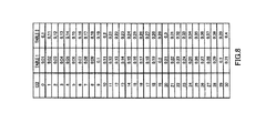
- FIG. 8 shows an example of a control channel CQI table
- FIG. 9 shows another example of a control channel CQI table
- FIG. 10 shows a block diagram showing the internal configuration of the MCS selection section according to Embodiment 2 of the present disclosure
- FIG. 11 shows an example of an offset lookup table
- FIG. 12 shows an example of a control channel CQI table
- FIG. 13 shows a CQI table according to Embodiment 3 of the present disclosure.
- FIG. 14 shows a CQI table according to Embodiment 4 of the present disclosure.
- FIG. 4 shows the relationships between the received SNRs and the SE (Spectral Efficiency) acquired from simulation results when required BLER of a data channel is 10%.
- FIG. 5 shows the relationships between the received SNRs and the SE when required BER of ACK/NACK of control channels is 0.01%.
- the difference in a received SNR between performance with AWGN and SE without frequency hopping is 5 dB in a data channel
- the difference is 9 dB in a control channel, and therefore the focus is placed upon severe deterioration of the control channel performance. That is, the focus is placed upon a significant difference between the data channel performance and the control channel performance in specific conditions.
- FIG. 6 is block diagram showing the configuration of a radio communication terminal apparatus according to Embodiment 1 of the present disclosure. Now, the configuration of the radio communication terminal apparatus will be explained with reference to FIG. 6 .
- Radio receiving section 102 converts a signal received via antenna 101 to a base band signal, and outputs the baseband signal to CP removing section 103 .
- CP removing section 103 removes the CP (Cyclic Prefix) from the baseband signal outputted from radio receiving section 102 , and outputs the resulting signal to FFT section 104 .
- FFT section 104 performs an FFT (Fast Fourier Transform) on the time-domain signal outputted from CP removing section 103 , and outputs the resulting frequency-domain signal to channel estimation section 105 and demodulation section 106 .
- FFT Fast Fourier Transform
- Channel estimation section 105 estimates a channel environment of the received signal using the pilot signal included in the signal outputted from FFT section 104 , and outputs the estimation result to demodulation section 106 .
- demodulation section 106 Based on the channel environment estimation result of the outputted from channel estimation section 105 , demodulation section 106 performs channel compensation for a signal acquired by removing control information such as the pilot signal from the received signal outputted from FFT section 104 , that is, performs channel compensation for data information. Further, demodulation section 106 demodulates the signal after the channel compensation based on the same MCS as the MCS used in the base station of the communicating party, and outputs the demodulated signal to decoding section 107 .
- Decoding section 107 performs error correction for the demodulated signal outputted from demodulation section 106 , and extracts information data sequences, CQI information and bandwidth information from the received signal. The CQI information and the bandwidth information are outputted to MCS selection section 108 .
- MCS selection section 108 having a CQI table (described later) reads from the CQI table an MCS pattern associated with the CQI information outputted from decoding section 107 , and determines the read MCS pattern as the MCS for a data channel (MCS 1). Further, based on the CQI information and the bandwidth information outputted from decoding section 107 , MCS selection section 108 determines an MCS pattern for the control channel (MCS 2) with reference to a plurality of CQI tables (described later). The determined MCS 1 is outputted to coding and modulation section 109 and MCS 2 is outputted to coding and modulation section 110 .
- MCS 2 control channel
- Coding and modulation section 109 encodes and modulates user data received as input (transmission data sequences) based on MCS 1 outputted from MCS selection section 108 , to generate data channel transmission data.
- the generated transmission data for the data channel is outputted to channel multiplexing section 111 .
- Coding and modulation section 110 encodes and modulates control data received as input based on MCS 2 outputted from MCS selection section 108 , to generate control channel transmission data.
- the generated transmission data for the control channel is outputted to channel multiplexing section 111 .
- Channel multiplexing section 111 performs time-division multiplexing of the transmission data for the data channel outputted from coding and modulation section 109 and the transmission data for the control channel outputted from coding and modulation section 110 .
- the multiplexed transmission data is outputted to DFT-s-OFDM section 112 .
- DFT-s-OFDM section 112 performs a discrete Fourier transform (DFT) on the transmission data outputted from channel multiplexing section 111 and performs time-frequency transform on the data of frequency components, to acquire a frequency-domain signal. Then, after the frequency-domain signal is mapped to transmission subcarriers, the mapped frequency-domain signal is subject to an IFFT (Inverse Fast Fourier Transform) processing, to be transformed to a time-domain signal. The acquired time-domain signal is outputted to CP addition section 113 .
- DFT discrete Fourier transform
- CP addition section 113 adds CPs to the frames in the transmission data sequences outputted from DFT-s-OFDM section 112 by duplicating data at the tail of each frame and by adding the duplicated data to the beginning of each frame, and outputs the transmission data with CPs to radio transmitting section 114 .
- Radio transmitting section 114 frequency-converts the baseband signal outputted from CP addition section 113 to a radio frequency band signal, and transmits the converted signal via antenna 101 .
- FIG. 7 is a block diagram showing an internal configuration of MCS selection section 108 shown in FIG. 6 .
- table selection MCS determination section 201 determines MCS 2 for the control channel with reference to the CQI table corresponding to the bandwidth among the control channel CQI tables shown in FIG. 8 .
- MCS determination section 202 determines MCS 1 for the data channel with reference to the data CQI table.
- FIG. 8 shows an example of a control channel CQI table.
- table 1 is the CQI table for a 500 kHz bandwidth or below
- table 2 is the CQI table for more than a 500 kHz bandwidth.
- SE in table 1 is set up lower than SE in table 2.
- the bandwidth is narrow as 500 kHz, that is, when frequency diversity effect is small, lower SE is selected.
- frequency diversity effect is significant
- higher SE is selected than the SE in table 1. Accordingly, when the frequency diversity effect is significant, few control signal resources make it possible to satisfy the required quality for the control channel compared in a case where diversity effect is small, so that it is possible to increase the amount of resources used for the data channel.
- Embodiment 1 when a data channel and a control channel are multiplexed and transmitted and adaptive modulation is applied to both channels, by providing one data channel CQI table and a plurality of control channel CQI tables, switching between a plurality of tables in accordance with a transmission bandwidth of a terminal, and determining the MCS for the control channel, it is possible to determine an MCS appropriate for the bandwidth and allocate radio resources used for the control channel adequately, thereby increasing radio resources used for the data channel. This makes it possible to improve data channel throughput.
- Embodiment 2 of the present disclosure The configuration of a radio communication terminal apparatus according to Embodiment 2 of the present disclosure is the same as shown in FIG. 6 of Embodiment 1, this embodiment will be explained with reference to FIG. 6 , and the overlapping explanation will be omitted.
- FIG. 10 is a block diagram showing the internal configuration of MCS selection section 108 according to Embodiment 2 of the present disclosure.
- CQI offset MCS determination section 301 calculates a control channel CQI using an offset lookup table shown in FIG. 11 , CQI information and equation 1.
- Control channel CQI CQI+ ⁇ offset[condition] (Equation 1)
- CQI offset MCS determination section 301 determines MCS 2 for the control channel with reference to the control channel CQI table shown in FIG. 12 .
- FIG. 11 shows an example of an offset lookup table.
- the offset is zero
- the data channel scheduling method is persistent scheduling
- the offset is two.
- offsets are provided by taking into account of CQI differences between two kinds of scheduling, that is, between normal scheduling (i.e. dynamic scheduling) and persistent scheduling.
- the offset is zero when the data channel is used with frequency hopping, and the offset is ⁇ 4 when the bandwidth is 1 RB (resource block) without frequency hopping.
- frequency diversity effect is small, for example, frequency hopping is not adopted in a frame and transmission is performed in a narrow band, the offsets are provided so as to select a lower MCS. This is because the relatively small number of bits is transmitted and coding gain is less likely to be acquired. By taking into account of the above reason, offsets are provided according to bandwidths.
- the offset is zero when a data channel transmission is the first, and the offset is ⁇ 2 upon retransmissions.
- Received quality is poorer than expected when a data channel is retransmitted. In such a case, received quality may deteriorate with regards to a control channel, and therefore an offset is provided so as to select a lower MCS.
- a terminal such as a data scheduling method, a bandwidth, frequency hopping in frames, and the number of data channel retransmissions, it is possible to set up a more adequate MCS. Accordingly, it is possible to satisfy required quality for a control channel using adequate control channel resources, so that the amount of resources used for a data channel can be increased.
- FIG. 12 is an example of a control channel CQI table.
- SE for 0 to 30 CQIs in a lookup table lower SE for ⁇ 1 to ⁇ 10 CQIs and higher SE for 31 to 37 are newly set.
- the lower SE part is mainly used when an offset is negative, and the higher SE part is mainly used when an offset is positive.
- Embodiment 2 when a data channel and a control channel are multiplexed and transmitted and adaptive modulation is applied to both channels, one data channel CQI table, one control channel CQI table in series formed in a larger size than that data channel CQI table and an offset lookup table formed with parameters of a terminal are provided to determine the MCS for the control channel by a CQI found by adding all the amounts of offsets read from a offset lookup table to a data channel CQI, so that it is possible to prevent memory from increasing and improve data channel throughput.
- FIG. 13 shows a CQI table according to Embodiment 3 of the present disclosure and by multiplying equation 1 by a scaling factor (N), a range set up in a lookup table can be bigger or smaller.
- a scaling factor is multiplied by a control channel CQI that is found by adding all the amounts of offsets, to calculate the new control channel CQI and to determine the MCS for the control channel, so that it is possible to prevent memory from increasing and improve data channel throughput even when there are control channels of different coding schemes.
- FIG. 14 shows a CQI table according to Embodiment 4 of the present disclosure.
- Embodiment 4 by multiplying by a scaling factor a control channel CQI found by adding all the amounts of offsets, changing the scaling factor according to the magnitude of the CQI, calculating a control channel CQI and determining the MCS for the control channel, even when there are control channels of different coding schemes, it is possible to prevent memory from increasing, and, furthermore, improve data channel throughput.
- “drop” may be included in a control channel CQI table not so as to transmit a control channel using the lowest SE (MCS).
- embodiments of the present disclosure can also be realized by software.
- Each function block employed in the description of each of the aforementioned embodiments may typically be implemented as an LSI constituted by an integrated circuit. These may be individual chips or partially or totally contained on a single chip. “LSI” is adopted here but this may also be referred to as “IC,” “system LSI,” “super LSI,” or “ultra LSI” depending on differing extents of integration.
- circuit integration is not limited to LSIs, and implementation using dedicated circuitry or general purpose processors is also possible.
- LSI manufacture utilization of a programmable FPGA (Field Programmable Gate Array) or a reconfigurable processor where connections and settings of circuit cells within an LSI can be reconfigured is also possible.
- FPGA Field Programmable Gate Array
- the radio transmitting apparatus and radio transmission method improves data channel throughput, and is applicable to, for example, mobile communication systems.
Abstract
A radio transmitting device and method enables reduction of an increase of CGI memories for the control channel and an improvement of the throughput of the data channel. When multiplex transmission through the control channel and the data channel is carried out and when adaptive modulation is applied to both channels, an MCS selecting section is provided with one CQI table for the data channel and CQI tables for the control channel, and a table selecting MCS determining section selects one of the tables depending on the transmission bandwidth of the terminal and determines the MCS of the control channel while looking up the selected CQI table.
Description
The present disclosure relates to a radio transmitting apparatus and a radio transmission method that are used in communication systems employing an adaptive modulation.
Presently, in 3GPP RAN LTE (Long Term Evolution) in uplink, single carrier transmission is gaining attention to achieve a low PAPR (Peak to Average Power Ratio). Further, studies are conducted for a scheme to perform “adaptive modulation (AMC: Adaptive Modulation and Coding)” for selecting a user-specific MCS (Modulation and Coding Scheme) pattern according to a CQI (Channel Quality Indicator) of users to achieve high throughput.
Further, to adopt adaptive modulation and hybrid ARQ to a downlink data channel, in uplink channel, downlink CQI information and downlink ACK/NACK information are transmitted in a control channel.
Further, studies are underway to transmit an uplink data channel and an uplink control channel in the same frame, and, furthermore, to determine an MCS for the control channel at the same time as an MCS for the data channel, using a CQI determining the MCS for the data channel (see, for example, Non-Patent Document 2).
Accordingly, similar to the MCS for a control channel, various modulation schemes and coding rates (hereinafter SE: Spectral Efficiency, and SE is defined as the number of bits per symbol×coding rate) are determined in accordance with CQIs. FIG. 2 shows a concrete example of a CQI table in which associations between data channel SE and control channel SE are shown. Hybrid ARQ is not adopted to this control channel. Accordingly, control channel SE is set up robust with respect to CQIs that is, the SE is set up to be low such that required quality is satisfied even in a poor reception environment.
- Non-Patent Document 1: R1-073344, Nokia, “Update to 64QAM CQI tables,” 3GPP TSG RAN WG1 Meeting #50, Athens, Greece, Aug. 20-24, 2007
- Non-Patent Document 2: 3GPP TS36.212 V8.0.0
However, with the above-described technique, in situations where the reception environment is not poor, SE read from the table fully satisfies required quality for a control channel, and therefore wasted radio resources are provided to use the control channel. As a result, there is a problem of decreasing data channel throughput.
This case will be explained as an example shown in FIG. 3 . As shown in FIG. 3 , when a data channel and a control channel are multiplexed and transmitted in the same frame, the size of resources that can be used is determined. When the reception environment is not poor, SE that fully satisfies the required quality for a control channel is set, and therefore control channel resources are wasted. However, these wasted resources cannot be used as data channel resources, and therefore data channel throughput decreases.
An embodiment provides a radio transmitting apparatus and a radio transmission method that facilitates improvement of data channel throughput.
The radio transmitting apparatus of an embodiment adopts the configuration including: a modulation and coding scheme selection section that switches associations between channel quality indicators and modulation and coding schemes according to a parameter of a radio communication terminal apparatus, to determine a modulation and coding scheme of a control channel based on the associations after the switching; and a coding and modulation section that encodes and modulates control data by the determined modulation and coding scheme.
The radio transmission method of an embodiment includes: a switching step of switching associations between channel quality indicators and modulation and coding schemes according to a parameter of radio communication terminal apparatus; a modulation and coding scheme selection step of determining a modulation and coding scheme of a control channel based on the associations after the switching; and a coding and modulation step of encoding and modulating control data by the determined modulation and coding scheme.
An embodiment provides an advantage of improving data channel throughput.
Now, embodiments of the present disclosure will be described in detail with reference to the accompanying drawings. FIG. 4 shows the relationships between the received SNRs and the SE (Spectral Efficiency) acquired from simulation results when required BLER of a data channel is 10%. Further, FIG. 5 shows the relationships between the received SNRs and the SE when required BER of ACK/NACK of control channels is 0.01%. According to the present embodiment, although the difference in a received SNR between performance with AWGN and SE without frequency hopping (a 180 kHz bandwidth) is 5 dB in a data channel, the difference is 9 dB in a control channel, and therefore the focus is placed upon severe deterioration of the control channel performance. That is, the focus is placed upon a significant difference between the data channel performance and the control channel performance in specific conditions.
Based on the channel environment estimation result of the outputted from channel estimation section 105, demodulation section 106 performs channel compensation for a signal acquired by removing control information such as the pilot signal from the received signal outputted from FFT section 104, that is, performs channel compensation for data information. Further, demodulation section 106 demodulates the signal after the channel compensation based on the same MCS as the MCS used in the base station of the communicating party, and outputs the demodulated signal to decoding section 107.
Decoding section 107 performs error correction for the demodulated signal outputted from demodulation section 106, and extracts information data sequences, CQI information and bandwidth information from the received signal. The CQI information and the bandwidth information are outputted to MCS selection section 108.
Coding and modulation section 109 encodes and modulates user data received as input (transmission data sequences) based on MCS 1 outputted from MCS selection section 108, to generate data channel transmission data. The generated transmission data for the data channel is outputted to channel multiplexing section 111.
Coding and modulation section 110 encodes and modulates control data received as input based on MCS 2 outputted from MCS selection section 108, to generate control channel transmission data. The generated transmission data for the control channel is outputted to channel multiplexing section 111.
DFT-s-OFDM section 112 performs a discrete Fourier transform (DFT) on the transmission data outputted from channel multiplexing section 111 and performs time-frequency transform on the data of frequency components, to acquire a frequency-domain signal. Then, after the frequency-domain signal is mapped to transmission subcarriers, the mapped frequency-domain signal is subject to an IFFT (Inverse Fast Fourier Transform) processing, to be transformed to a time-domain signal. The acquired time-domain signal is outputted to CP addition section 113.
Based on a CQI received as input, MCS determination section 202 determines MCS 1 for the data channel with reference to the data CQI table.
In this way, according to Embodiment 1, when a data channel and a control channel are multiplexed and transmitted and adaptive modulation is applied to both channels, by providing one data channel CQI table and a plurality of control channel CQI tables, switching between a plurality of tables in accordance with a transmission bandwidth of a terminal, and determining the MCS for the control channel, it is possible to determine an MCS appropriate for the bandwidth and allocate radio resources used for the control channel adequately, thereby increasing radio resources used for the data channel. This makes it possible to improve data channel throughput.
Although a case has been explained with the present embodiment as an example where a CQI table is selected based only on the transmission bandwidth, as shown in FIG. 9 , it is equally possible to select four CQI tables based on data channel scheduling methods in addition to a bandwidth. When persistent scheduling is used for a data channel, a low CQI is reported to make the MCS for the data channel robust. In this case, it is possible to increase the amount of resources used for the data channel by taking into account the difference in CQI between two kinds of scheduling, that is, normal scheduling (i.e. dynamic scheduling) and persistent scheduling, by configuring a plurality of control channel CQI tables and making the MCS and resources of use of the control channel adequate.
The configuration of a radio communication terminal apparatus according to Embodiment 2 of the present disclosure is the same as shown in FIG. 6 of Embodiment 1, this embodiment will be explained with reference to FIG. 6 , and the overlapping explanation will be omitted.
Control channel CQI=CQI+Σoffset[condition] (Equation 1)
Further, based on that control channel CQI, CQI offset MCS determination section 301 determines MCS 2 for the control channel with reference to the control channel CQI table shown in FIG. 12 .
Further, the offset is zero when the data channel is used with frequency hopping, and the offset is −4 when the bandwidth is 1 RB (resource block) without frequency hopping. When frequency diversity effect is small, for example, frequency hopping is not adopted in a frame and transmission is performed in a narrow band, the offsets are provided so as to select a lower MCS. This is because the relatively small number of bits is transmitted and coding gain is less likely to be acquired. By taking into account of the above reason, offsets are provided according to bandwidths.
Furthermore, the offset is zero when a data channel transmission is the first, and the offset is −2 upon retransmissions. Received quality is poorer than expected when a data channel is retransmitted. In such a case, received quality may deteriorate with regards to a control channel, and therefore an offset is provided so as to select a lower MCS.
As explained above, according to parameters of a terminal, such as a data scheduling method, a bandwidth, frequency hopping in frames, and the number of data channel retransmissions, it is possible to set up a more adequate MCS. Accordingly, it is possible to satisfy required quality for a control channel using adequate control channel resources, so that the amount of resources used for a data channel can be increased.
In this way, according to Embodiment 2, when a data channel and a control channel are multiplexed and transmitted and adaptive modulation is applied to both channels, one data channel CQI table, one control channel CQI table in series formed in a larger size than that data channel CQI table and an offset lookup table formed with parameters of a terminal are provided to determine the MCS for the control channel by a CQI found by adding all the amounts of offsets read from a offset lookup table to a data channel CQI, so that it is possible to prevent memory from increasing and improve data channel throughput.
Control channel CQI=floor(N×(CQI+Σoffset[condition])) (Equation 2)
where N is a decimal.
To apply a case where a coding scheme varies like between an uplink CQI channel and ACK/NACK channels used in LTE, by changing the value, N, a control channel is applicable to different coding schemes. That is, an uplink CQI channel is applicable by only changing offset and value N, and ACK/NACK channels are applicable by an offset (N=1) only, so that it is possible to refer to MCSs of two kinds of control channels from the same CQI table.
In this way, according to Embodiment 3, a scaling factor is multiplied by a control channel CQI that is found by adding all the amounts of offsets, to calculate the new control channel CQI and to determine the MCS for the control channel, so that it is possible to prevent memory from increasing and improve data channel throughput even when there are control channels of different coding schemes.
In this way, according to Embodiment 4, by multiplying by a scaling factor a control channel CQI found by adding all the amounts of offsets, changing the scaling factor according to the magnitude of the CQI, calculating a control channel CQI and determining the MCS for the control channel, even when there are control channels of different coding schemes, it is possible to prevent memory from increasing, and, furthermore, improve data channel throughput.
Although cases have been explained with Embodiments 3 and 4 where a primary linear process of multiplying N is adopted, a higher linear process may be adopted.
With the above embodiments, “drop” may be included in a control channel CQI table not so as to transmit a control channel using the lowest SE (MCS).
Further, with the above embodiments, when a calculated control channel CQI is outside the range of the control channel CQI table, it is possible to use the SE (MCSs) at both ends of the CQI table or use extrapolation.
Further, although cases have been described with the above embodiments as examples where embodiments of the present disclosure is configured by hardware, embodiments of the present disclosure can also be realized by software.
Each function block employed in the description of each of the aforementioned embodiments may typically be implemented as an LSI constituted by an integrated circuit. These may be individual chips or partially or totally contained on a single chip. “LSI” is adopted here but this may also be referred to as “IC,” “system LSI,” “super LSI,” or “ultra LSI” depending on differing extents of integration.
Further, the method of circuit integration is not limited to LSIs, and implementation using dedicated circuitry or general purpose processors is also possible. After LSI manufacture, utilization of a programmable FPGA (Field Programmable Gate Array) or a reconfigurable processor where connections and settings of circuit cells within an LSI can be reconfigured is also possible.
Further, if integrated circuit technology comes out to replace LSI's as a result of the advancement of semiconductor technology or a derivative other technology, it is naturally also possible to carry out function block integration using this technology. Application of biotechnology is also possible.
The radio transmitting apparatus and radio transmission method according to at least one embodiment improves data channel throughput, and is applicable to, for example, mobile communication systems.
Claims (29)
1. A radio transmission apparatus comprising:
a coding unit configured to code one form of control data using a coding scheme that is obtained based on multiplying a value related to a modulation and coding scheme (MCS) for a data channel and an offset value, the offset value being pre-stored for said one form of the control data in the radio transmission apparatus; and
a radio transmitting unit configured to transmit data in the data channel and said one form of the control data coded with the coding scheme.
2. The radio transmission apparatus according to claim 1 wherein said coding unit is configured to code a first form of control data using first control coding scheme that is obtained based on multiplying a value related to the MCS for the data channel and a first offset value for the first form of the control data, and to code a second form of control data using a second control coding scheme that is obtained based on multiplying a value related to the MCS for the data channel and a second offset value for the second form of the control data.
3. The radio transmission apparatus according to claim 2 wherein the first coding scheme used to code said first form of control data is different from the second coding scheme used to code said second form of control data.
4. The radio transmission apparatus according to claim 1 wherein said one form of the control data includes an ACK/NACK or a channel quality indicator (CQI).
5. The radio transmission apparatus according to claim 1 wherein said transmitting unit multiplexes and transmits the data and said one form of the coded control data.
6. The radio transmission apparatus according to claim 1 , further comprising a receiving unit configured to receive control information, wherein said coding unit determines the MCS for the data channel based on the received control information.
7. The radio transmission apparatus according to claim 6 wherein the control information includes a channel quality indicator (CQI).
8. The radio transmission apparatus according to claim 1 wherein the offset value is obtained by multiplying a base offset value with a scale value for said one form of the control data.
9. The radio transmission apparatus according to claim 1 wherein the offset value is associated with a parameter of the radio transmission apparatus.
10. The radio transmission apparatus according to claim 9 wherein the parameter is a transmission bandwidth parameter, a scheduling scheme parameter, a frequency hopping parameter, or a number of retransmissions parameter.
11. The radio transmission apparatus according to claim 1 wherein a single offset value is pre-stored for said one form of the control data and the single offset value is multiplied regardless of the value related to the MCS for the data channel.
12. The radio transmission apparatus according to claim 11 wherein a first offset value is pre-stored for the control data including an ACK/NACK and is multiplied regardless of the value related to the MCS for the data channel, and a second offset value is pre-stored for the control data including a channel quality indicator (CQI) and is multiplied regardless of the value related to in the MCS for the data channel.
13. The radio transmission apparatus according to claim 1 wherein the value related to the MCS for the data channel includes a value related to a coding rate.
14. The radio transmission apparatus according to claim 1 wherein a single offset value is pre-stored for said one form of the control data and the single offset value is multiplied regardless of the value related to the MCS for the data channel, and wherein the value related to the MCS for the data channel includes a value related to a coding rate.
15. A radio transmission method performed by a radio transmission apparatus, the method comprising:
coding one form of control data using a coding scheme that is obtained based on multiplying a value related to a modulation and coding scheme (MCS) for a radio data channel and an offset value, the offset value being pre-stored for said one form of the control data in the radio transmission apparatus; and
transmitting data in the radio data channel and said one form of the control data coded with a coding scheme.
16. An integrated circuit, comprising:
communication control circuitry, which, in operation, codes one form of control data using a coding scheme that is obtained based on multiplying a value related to a modulation and coding scheme (MCS) for a data channel and an offset value, the offset value being pre-stored for said one form of the control data in the integrated circuit; and
one or more output nodes, which, in operation, output data to the data channel and said one form of the control data coded with the coding scheme to a control channel.
17. The integrated circuit of claim 16 wherein the communication control circuitry, in operation, codes a first form of control data using a first control coding scheme that is obtained based on multiplying a value related to the MCS for the data channel and a first offset value for the first form of the control data, and codes a second form of control data using a second control coding scheme that is obtained based on multiplying a value related to the MCS for the data channel and a second offset value for the second form of the control data.
18. The integrated circuit of claim 17 wherein the first coding scheme used to code said first form of control data is different from the second coding scheme used to code said second form of control data.
19. The integrated circuit of claim 16 wherein said one form of the control data includes an ACK/NACK or a channel quality indicator (CQI).
20. The integrated circuit of claim 16 wherein the communication control circuitry, in operation, multiplexes and outputs the data and said one form of the coded control data.
21. The integrated circuit of claim 16 , further comprising:
one or more input nodes, which, in operation receive control information, wherein said communication control circuitry, in operation, determines the MCS for the data channel based on the received control information.
22. The integrated circuit of claim 21 wherein the control information includes a channel quality indicator (CQI).
23. The integrated circuit of claim 16 wherein the offset value is obtained by multiplying a base offset value with a scale value for said one form of the control data.
24. The integrated circuit of claim 16 wherein the offset value is associated with a parameter of the radio transmission apparatus.
25. The integrated circuit of claim 24 wherein the parameter is a transmission bandwidth parameter, a scheduling scheme parameter, a frequency hopping parameter, or a number of retransmissions parameter.
26. The integrated circuit of claim 16 wherein a single offset value is pre-stored for said one form of the control data and the single offset value is multiplied regardless of the value related to the MCS for the data channel.
27. The integrated circuit of claim 26 wherein a first offset value is pre-stored for the control data including an ACK/NACK and is multiplied regardless of the value related to the MCS for the data channel, and a second offset value is pre-stored for the control data including a channel quality indicator (CQI) and is multiplied regardless of the value related to the MCS for the data channel.
28. The integrated circuit of claim 16 wherein the value related to the MCS for the data channel includes a value related to a coding rate.
29. The integrated circuit of claim 16 wherein a single offset value is pre-stored for said one form of the control data and the single offset value is multiplied regardless of the value related to the MCS for the data channel, and wherein the value related to the MCS for the data channel includes a value related to a coding rate.
Priority Applications (5)
| Application Number | Priority Date | Filing Date | Title |
|---|---|---|---|
| US14/509,955 US9467248B2 (en) | 2008-01-04 | 2014-10-08 | Radio transmission device and method |
| US15/258,739 US9787427B2 (en) | 2008-01-04 | 2016-09-07 | Radio transmission device and method |
| US15/689,503 US10225042B2 (en) | 2008-01-04 | 2017-08-29 | Radio transmission device and method |
| US16/254,274 US10686550B2 (en) | 2008-01-04 | 2019-01-22 | Radio transmission device and method |
| US16/871,955 US11233598B2 (en) | 2008-01-04 | 2020-05-11 | Radio transmission device and method |
Applications Claiming Priority (7)
| Application Number | Priority Date | Filing Date | Title |
|---|---|---|---|
| JP2008000199 | 2008-01-04 | ||
| JP2008-000199 | 2008-01-04 | ||
| PCT/JP2008/004009 WO2009087743A1 (en) | 2008-01-04 | 2008-12-26 | Radio transmitting device and radio transmitting method |
| US81150910A | 2010-07-01 | 2010-07-01 | |
| US13/325,969 US8340212B2 (en) | 2008-01-04 | 2011-12-14 | Integrated circuit for radio transmission |
| US13/686,598 US8897389B2 (en) | 2008-01-04 | 2012-11-27 | Radio transmission device and method |
| US14/509,955 US9467248B2 (en) | 2008-01-04 | 2014-10-08 | Radio transmission device and method |
Related Parent Applications (1)
| Application Number | Title | Priority Date | Filing Date |
|---|---|---|---|
| US13/686,598 Continuation US8897389B2 (en) | 2008-01-04 | 2012-11-27 | Radio transmission device and method |
Related Child Applications (1)
| Application Number | Title | Priority Date | Filing Date |
|---|---|---|---|
| US15/258,739 Continuation US9787427B2 (en) | 2008-01-04 | 2016-09-07 | Radio transmission device and method |
Publications (2)
| Publication Number | Publication Date |
|---|---|
| US20150023307A1 US20150023307A1 (en) | 2015-01-22 |
| US9467248B2 true US9467248B2 (en) | 2016-10-11 |
Family
ID=40852868
Family Applications (8)
| Application Number | Title | Priority Date | Filing Date |
|---|---|---|---|
| US12/811,509 Active US8098759B2 (en) | 2008-01-04 | 2008-12-26 | Radio transmitting device and radio transmitting method |
| US13/325,969 Active US8340212B2 (en) | 2008-01-04 | 2011-12-14 | Integrated circuit for radio transmission |
| US13/686,598 Active 2029-01-19 US8897389B2 (en) | 2008-01-04 | 2012-11-27 | Radio transmission device and method |
| US14/509,955 Active 2029-06-26 US9467248B2 (en) | 2008-01-04 | 2014-10-08 | Radio transmission device and method |
| US15/258,739 Active US9787427B2 (en) | 2008-01-04 | 2016-09-07 | Radio transmission device and method |
| US15/689,503 Active US10225042B2 (en) | 2008-01-04 | 2017-08-29 | Radio transmission device and method |
| US16/254,274 Active US10686550B2 (en) | 2008-01-04 | 2019-01-22 | Radio transmission device and method |
| US16/871,955 Active 2029-03-04 US11233598B2 (en) | 2008-01-04 | 2020-05-11 | Radio transmission device and method |
Family Applications Before (3)
| Application Number | Title | Priority Date | Filing Date |
|---|---|---|---|
| US12/811,509 Active US8098759B2 (en) | 2008-01-04 | 2008-12-26 | Radio transmitting device and radio transmitting method |
| US13/325,969 Active US8340212B2 (en) | 2008-01-04 | 2011-12-14 | Integrated circuit for radio transmission |
| US13/686,598 Active 2029-01-19 US8897389B2 (en) | 2008-01-04 | 2012-11-27 | Radio transmission device and method |
Family Applications After (4)
| Application Number | Title | Priority Date | Filing Date |
|---|---|---|---|
| US15/258,739 Active US9787427B2 (en) | 2008-01-04 | 2016-09-07 | Radio transmission device and method |
| US15/689,503 Active US10225042B2 (en) | 2008-01-04 | 2017-08-29 | Radio transmission device and method |
| US16/254,274 Active US10686550B2 (en) | 2008-01-04 | 2019-01-22 | Radio transmission device and method |
| US16/871,955 Active 2029-03-04 US11233598B2 (en) | 2008-01-04 | 2020-05-11 | Radio transmission device and method |
Country Status (10)
| Country | Link |
|---|---|
| US (8) | US8098759B2 (en) |
| EP (4) | EP2472761B1 (en) |
| JP (2) | JP4598149B2 (en) |
| KR (1) | KR101531413B1 (en) |
| CN (3) | CN103560866B (en) |
| AU (1) | AU2008346019B2 (en) |
| BR (2) | BRPI0822232B1 (en) |
| ES (1) | ES2388121T3 (en) |
| RU (1) | RU2479133C2 (en) |
| WO (1) | WO2009087743A1 (en) |
Families Citing this family (39)
| Publication number | Priority date | Publication date | Assignee | Title |
|---|---|---|---|---|
| KR101531413B1 (en) * | 2008-01-04 | 2015-06-24 | 고도 가이샤 아이피 브릿지 1 | Radio transmitting device and radio transmitting method |
| EP2478722A4 (en) * | 2009-09-15 | 2013-12-25 | Blackberry Ltd | Adaptive modulation and coding scheme adjustment in wireless networks |
| US8792469B2 (en) * | 2009-10-02 | 2014-07-29 | Sharp Laboratories Of America, Inc. | Coding a control message with determined data code block repetition |
| US8842625B2 (en) * | 2009-10-14 | 2014-09-23 | Telefonaktiebolaget L M Ericsson (Publ) | Wireless scheduling considering overhead cost estimate |
| WO2011047496A1 (en) * | 2009-10-19 | 2011-04-28 | Telefonaktiebolaget L M Ericsson (Publ) | Method and arrangement in a wireless communication system |
| KR101656291B1 (en) * | 2010-05-03 | 2016-09-22 | 삼성전자주식회사 | Apparatus and method for improving transmission efficiency in wireless communication system |
| WO2012050329A2 (en) * | 2010-10-11 | 2012-04-19 | 엘지전자 주식회사 | Method and device for transmitting uplink control information when retransmitting uplink data in wireless access system |
| JP5798317B2 (en) * | 2010-11-26 | 2015-10-21 | 京セラ株式会社 | Radio base station and communication control method |
| JP5735783B2 (en) * | 2010-11-26 | 2015-06-17 | 京セラ株式会社 | Radio base station and communication control method |
| WO2012070660A1 (en) * | 2010-11-26 | 2012-05-31 | 京セラ株式会社 | Wireless base station and communication control method |
| JP2012239052A (en) * | 2011-05-12 | 2012-12-06 | Nec Corp | Wireless communication device and wireless communication method |
| CN102202415B (en) * | 2011-05-18 | 2019-01-22 | 中兴通讯股份有限公司 | A kind of transmission method and system of Physical Random Access Channel |
| ES2806074T3 (en) * | 2011-11-11 | 2021-02-16 | Itron Global Sarl | Multi-channel, multi-modulation and multi-frequency communication with a radio transceiver |
| US8995361B2 (en) | 2011-11-11 | 2015-03-31 | Itron, Inc. | Multi-channel, multi-modulation, multi-rate communication with a radio transceiver |
| CN107070597B (en) * | 2012-03-02 | 2021-05-11 | 华为技术有限公司 | Information transmission method and equipment |
| EP2639983A1 (en) * | 2012-03-16 | 2013-09-18 | Panasonic Corporation | MCS table adaptation for low power ABS |
| US8885617B2 (en) * | 2012-09-05 | 2014-11-11 | Qualcomm Incorporated | Methods and devices for employing a modulation and coding scheme for a data block |
| US9713189B2 (en) * | 2012-11-07 | 2017-07-18 | Telefonaktiebolaget Lm Ericsson (Publ) | Multiple outer loop link adaptation |
| US9407417B2 (en) | 2013-01-09 | 2016-08-02 | Qualcomm Incorporated | Identifying modulation and coding schemes and channel quality indicators |
| CN104052572B (en) * | 2013-03-11 | 2019-07-02 | 北京三星通信技术研究有限公司 | A kind of downlink transmission method and subscriber terminal equipment |
| US9344240B2 (en) | 2013-04-04 | 2016-05-17 | Samsung Electronics Co., Ltd. | 256QAM signal transmission/reception method and apparatus for use in mobile communication system |
| EP3041284B1 (en) | 2013-09-18 | 2019-03-13 | Huawei Technologies Co., Ltd. | Data transmission methods, base station and user equipment |
| CN103546206A (en) * | 2013-10-31 | 2014-01-29 | 宇龙计算机通信科技(深圳)有限公司 | Method for reducing link self-adaptation feedback information amount, wireless telecommunication equipment and wireless telecommunication system |
| CN104919738B (en) * | 2013-10-31 | 2018-10-09 | 华为技术有限公司 | Information notice reports and data receiver method, equipment |
| MX359492B (en) * | 2013-10-31 | 2018-09-07 | Huawei Tech Co Ltd | Method and device for information announcement and reporting and data reception. |
| US20150195819A1 (en) * | 2014-01-06 | 2015-07-09 | Intel IP Corporation | Systems and methods for modulation and coding scheme selection and configuration |
| JP6260360B2 (en) | 2014-03-07 | 2018-01-17 | 富士通株式会社 | Optical transmission device and optical transmission system |
| EP3269060B1 (en) | 2015-03-09 | 2019-05-08 | Telefonaktiebolaget LM Ericsson (publ) | Outer loop link adaptation with bundled feedback |
| WO2017117797A1 (en) * | 2016-01-08 | 2017-07-13 | Apple Inc. | Apparatus, systems and methods for adaptive downlink scheduling and link adaptation |
| US10425922B2 (en) * | 2016-02-20 | 2019-09-24 | Qualcomm Incorporated | Communication of uplink control information |
| US10397904B2 (en) | 2016-02-20 | 2019-08-27 | Qualcomm Incorporated | Communication of uplink control information |
| MX2019008680A (en) * | 2017-01-23 | 2019-09-18 | Guangdong Oppo Mobile Telecommunications Corp Ltd | Radio communication method, terminal device, and network device. |
| US10187895B1 (en) * | 2017-02-03 | 2019-01-22 | Sprint Spectrum L.P. | Dynamic scaling down of resource block allocation based on disproportionate allocation and based on use of high-order MCS |
| CN108631976B (en) | 2017-03-23 | 2021-07-16 | 华为技术有限公司 | Communication method and device |
| CN108964831B (en) * | 2017-05-18 | 2023-11-17 | 华为技术有限公司 | Signal transmission method and device |
| US10944501B2 (en) * | 2017-12-15 | 2021-03-09 | Mediatek Singapore Pte. Ltd. | Method and apparatus for determining modulation and coding scheme table in mobile communications |
| US10708112B2 (en) | 2018-01-12 | 2020-07-07 | At&T Intellectual Property I, L.P. | Dynamic indication of higher order modulation and coding scheme table |
| WO2020087351A1 (en) * | 2018-10-31 | 2020-05-07 | 华为技术有限公司 | Data transmission method and device, network apparatus, and storage medium |
| EP3883311A4 (en) * | 2018-11-28 | 2022-09-28 | Beijing Xiaomi Mobile Software Co., Ltd. | Downlink control signaling detection method and apparatus, and system |
Citations (25)
| Publication number | Priority date | Publication date | Assignee | Title |
|---|---|---|---|---|
| JP2003283471A (en) | 2002-03-22 | 2003-10-03 | Matsushita Electric Ind Co Ltd | Base station device and packet transmission method |
| US20050105483A1 (en) | 2002-10-08 | 2005-05-19 | Toshiyuki Uehara | Base station apparatus and communication terminal apparatus |
| US20060093024A1 (en) | 2004-11-04 | 2006-05-04 | Interdigital Technology Corporation | Wireless communication method and apparatus for adaptively biasing channel quality indicators to maintain a desired block error rate |
| WO2006059565A1 (en) | 2004-11-30 | 2006-06-08 | Matsushita Electric Industrial Co., Ltd. | Wireless communication apparatus and wireless communication method in multicarrier communication |
| WO2006082761A1 (en) | 2005-02-02 | 2006-08-10 | Matsushita Electric Industrial Co., Ltd. | Base station apparatus and resource assigning method |
| JP2006211017A (en) | 2005-01-25 | 2006-08-10 | Matsushita Electric Ind Co Ltd | Base station apparatus, communication terminal, and resource allocation method |
| WO2006098105A1 (en) | 2005-03-17 | 2006-09-21 | Sharp Kabushiki Kaisha | Adaptive modulation control system, and radio communication device |
| WO2006106613A1 (en) | 2005-03-31 | 2006-10-12 | Ntt Docomo, Inc. | Radio communication device, and radio communication method |
| KR20070000807A (en) | 2005-06-28 | 2007-01-03 | 에스케이 텔레콤주식회사 | Packet schedulling apparatus and method thereof |
| WO2007020996A1 (en) | 2005-08-19 | 2007-02-22 | Matsushita Electric Industrial Co., Ltd. | Wireless communication apparatus and wireless communication method |
| WO2007037412A1 (en) | 2005-09-30 | 2007-04-05 | Matsushita Electric Industrial Co., Ltd. | Radio transmission device, and radio transmission method |
| US20070082619A1 (en) | 2005-10-06 | 2007-04-12 | Interdigital Technology Corporation | Method and apparatus for controlling downlink transmission power for ofdma based evolved utra |
| JP2007150906A (en) | 2005-11-29 | 2007-06-14 | Kyocera Corp | Base station, wireless communication terminal, and wireless communication system |
| WO2007136002A1 (en) | 2006-05-19 | 2007-11-29 | Panasonic Corporation | Radio transmission device and radio transmission method |
| US20080153425A1 (en) | 2006-12-18 | 2008-06-26 | Samsung Electronics Co., Ltd. | Method and apparatus for transmitting/receiving data and control information through an uplink in a wireless communication system |
| WO2008078733A1 (en) | 2006-12-26 | 2008-07-03 | Panasonic Corporation | Radio communication base station device and control channel mcs control method |
| US20080233964A1 (en) | 2007-03-19 | 2008-09-25 | Freescale Semiconductor, Inc. | Uplink control channel allocation |
| US20080268862A1 (en) * | 2007-04-30 | 2008-10-30 | Mark Kent | Method and system for best-m cqi feedback together with pmi feedback |
| US20090059844A1 (en) | 2007-06-25 | 2009-03-05 | Lg Electronics Inc. | Method of transmitting data in multiple antenna system |
| US20090232101A1 (en) | 2008-02-04 | 2009-09-17 | Samsung Electronics Co., Ltd. | Control and data multiplexing in communication systems |
| US20100027450A1 (en) | 2006-11-01 | 2010-02-04 | Qualcomm Incorporated | Multiplexing of control and data with varying power offsets in a SC-FDMA system |
| US20100103899A1 (en) | 2004-08-07 | 2010-04-29 | Yong-Jun Kwak | Method and apparatus for signaling user equipment status information for uplink packet transmission in a soft handover region |
| US8098759B2 (en) | 2008-01-04 | 2012-01-17 | Panasonic Corporation | Radio transmitting device and radio transmitting method |
| US8812048B2 (en) * | 2007-03-07 | 2014-08-19 | Interdigital Technology Corporation | Combined open loop/closed loop method for controlling uplink power of a mobile station |
| US9036516B2 (en) * | 2007-03-21 | 2015-05-19 | Broadcom Corporation | Method and system for adaptive allocation of feedback resources for CQI and transmit pre-coding |
Family Cites Families (8)
| Publication number | Priority date | Publication date | Assignee | Title |
|---|---|---|---|---|
| US6307849B1 (en) * | 1997-09-08 | 2001-10-23 | Qualcomm Incorporated | Method and system for changing forward traffic channel power allocation during soft handoff |
| KR20060003764A (en) * | 2004-07-07 | 2006-01-11 | 삼성전자주식회사 | Method for synchronous automatic repeat request in a mobile communication system |
| US20060251180A1 (en) * | 2005-05-03 | 2006-11-09 | Motorola, Inc. | Method and system for selecting mcs in a communication network |
| EP1746776A3 (en) * | 2005-07-19 | 2011-06-15 | Samsung Electronics Co., Ltd. | System and method for scheduling uplink in a communication system |
| JP2008000199A (en) | 2006-06-20 | 2008-01-10 | Tdk Corp | Motion sensor |
| CA2658367C (en) | 2006-08-25 | 2015-04-28 | Qualcomm Incorporated | Cdma wireless communication systems |
| US7944927B2 (en) * | 2007-09-14 | 2011-05-17 | Intel Corporation | Efficient use of persistent scheduling with OFDMA wireless communications |
| US7970001B2 (en) | 2007-10-01 | 2011-06-28 | Panasonic Corporation | Receiver apparatus and communication method in a communication system wherein a plurality of system bandwidths are set |
-
2008
- 2008-12-26 KR KR1020107012645A patent/KR101531413B1/en active IP Right Grant
- 2008-12-26 EP EP12162148.6A patent/EP2472761B1/en active Active
- 2008-12-26 BR BRPI0822232A patent/BRPI0822232B1/en active IP Right Grant
- 2008-12-26 RU RU2010127248/07A patent/RU2479133C2/en active
- 2008-12-26 JP JP2009548817A patent/JP4598149B2/en active Active
- 2008-12-26 WO PCT/JP2008/004009 patent/WO2009087743A1/en active Application Filing
- 2008-12-26 AU AU2008346019A patent/AU2008346019B2/en active Active
- 2008-12-26 CN CN201310559751.2A patent/CN103560866B/en active Active
- 2008-12-26 EP EP20172875.5A patent/EP3709545A1/en not_active Withdrawn
- 2008-12-26 ES ES08870441T patent/ES2388121T3/en active Active
- 2008-12-26 EP EP08870441A patent/EP2228933B1/en active Active
- 2008-12-26 BR BR122019024638-6A patent/BR122019024638B1/en active IP Right Grant
- 2008-12-26 US US12/811,509 patent/US8098759B2/en active Active
- 2008-12-26 EP EP18169817.6A patent/EP3373491B1/en active Active
- 2008-12-26 CN CN201410764164.1A patent/CN104468046B/en active Active
- 2008-12-26 CN CN200880121567.7A patent/CN101904123B/en active Active
-
2010
- 2010-09-21 JP JP2010210863A patent/JP5283674B2/en active Active
-
2011
- 2011-12-14 US US13/325,969 patent/US8340212B2/en active Active
-
2012
- 2012-11-27 US US13/686,598 patent/US8897389B2/en active Active
-
2014
- 2014-10-08 US US14/509,955 patent/US9467248B2/en active Active
-
2016
- 2016-09-07 US US15/258,739 patent/US9787427B2/en active Active
-
2017
- 2017-08-29 US US15/689,503 patent/US10225042B2/en active Active
-
2019
- 2019-01-22 US US16/254,274 patent/US10686550B2/en active Active
-
2020
- 2020-05-11 US US16/871,955 patent/US11233598B2/en active Active
Patent Citations (36)
| Publication number | Priority date | Publication date | Assignee | Title |
|---|---|---|---|---|
| US20040196801A1 (en) | 2002-03-22 | 2004-10-07 | Katsuhiko Hiramatsu | Base station apparatus and packet transmission method |
| JP2003283471A (en) | 2002-03-22 | 2003-10-03 | Matsushita Electric Ind Co Ltd | Base station device and packet transmission method |
| US20050105483A1 (en) | 2002-10-08 | 2005-05-19 | Toshiyuki Uehara | Base station apparatus and communication terminal apparatus |
| US20100103899A1 (en) | 2004-08-07 | 2010-04-29 | Yong-Jun Kwak | Method and apparatus for signaling user equipment status information for uplink packet transmission in a soft handover region |
| US20060093024A1 (en) | 2004-11-04 | 2006-05-04 | Interdigital Technology Corporation | Wireless communication method and apparatus for adaptively biasing channel quality indicators to maintain a desired block error rate |
| WO2006052448A2 (en) | 2004-11-04 | 2006-05-18 | Interdigital Technology Corporation | Wireless communication method and apparatus for adaptively biasing channel quality indicators to maintain a desired block error rate |
| WO2006059565A1 (en) | 2004-11-30 | 2006-06-08 | Matsushita Electric Industrial Co., Ltd. | Wireless communication apparatus and wireless communication method in multicarrier communication |
| US20080132172A1 (en) | 2004-11-30 | 2008-06-05 | Matsushita Electric Industrial Co., Ltd. | Wireless Communication Apparatus and Wireless Communication Method in Multicarrier Communication |
| JP2006211017A (en) | 2005-01-25 | 2006-08-10 | Matsushita Electric Ind Co Ltd | Base station apparatus, communication terminal, and resource allocation method |
| WO2006082761A1 (en) | 2005-02-02 | 2006-08-10 | Matsushita Electric Industrial Co., Ltd. | Base station apparatus and resource assigning method |
| US20090010211A1 (en) | 2005-02-02 | 2009-01-08 | Matsushita Electric Industrial Co., Ltd. | Base station apparatus and resource assigning method |
| WO2006098105A1 (en) | 2005-03-17 | 2006-09-21 | Sharp Kabushiki Kaisha | Adaptive modulation control system, and radio communication device |
| US20080188184A1 (en) | 2005-03-17 | 2008-08-07 | Sharp Kabushiki Kaisha | Adaptive Modulation Control System and Wireless Communication Apparatus |
| US20090213955A1 (en) | 2005-03-31 | 2009-08-27 | Ntt Docomo, Inc. | Radio communication apparatus and a radio communication method |
| WO2006106613A1 (en) | 2005-03-31 | 2006-10-12 | Ntt Docomo, Inc. | Radio communication device, and radio communication method |
| KR20070000807A (en) | 2005-06-28 | 2007-01-03 | 에스케이 텔레콤주식회사 | Packet schedulling apparatus and method thereof |
| WO2007020996A1 (en) | 2005-08-19 | 2007-02-22 | Matsushita Electric Industrial Co., Ltd. | Wireless communication apparatus and wireless communication method |
| US20090109999A1 (en) | 2005-08-19 | 2009-04-30 | Kenichi Kuri | Wireless communication apparatus and wireless communication method |
| EP1914948A1 (en) | 2005-09-30 | 2008-04-23 | Matsushita Electric Industrial Co., Ltd. | Radio transmission device, and radio transmission method |
| WO2007037412A1 (en) | 2005-09-30 | 2007-04-05 | Matsushita Electric Industrial Co., Ltd. | Radio transmission device, and radio transmission method |
| US20070082619A1 (en) | 2005-10-06 | 2007-04-12 | Interdigital Technology Corporation | Method and apparatus for controlling downlink transmission power for ofdma based evolved utra |
| JP2007150906A (en) | 2005-11-29 | 2007-06-14 | Kyocera Corp | Base station, wireless communication terminal, and wireless communication system |
| US20090185638A1 (en) | 2006-05-19 | 2009-07-23 | Daichi Imamura | Radio transmission device and radio transmission method |
| WO2007136002A1 (en) | 2006-05-19 | 2007-11-29 | Panasonic Corporation | Radio transmission device and radio transmission method |
| US20100027450A1 (en) | 2006-11-01 | 2010-02-04 | Qualcomm Incorporated | Multiplexing of control and data with varying power offsets in a SC-FDMA system |
| US20080153425A1 (en) | 2006-12-18 | 2008-06-26 | Samsung Electronics Co., Ltd. | Method and apparatus for transmitting/receiving data and control information through an uplink in a wireless communication system |
| US20090290541A1 (en) | 2006-12-26 | 2009-11-26 | Panasonic Corporation | Radio communication base station device and control channel mcs control method |
| WO2008078733A1 (en) | 2006-12-26 | 2008-07-03 | Panasonic Corporation | Radio communication base station device and control channel mcs control method |
| US8812048B2 (en) * | 2007-03-07 | 2014-08-19 | Interdigital Technology Corporation | Combined open loop/closed loop method for controlling uplink power of a mobile station |
| US20080233964A1 (en) | 2007-03-19 | 2008-09-25 | Freescale Semiconductor, Inc. | Uplink control channel allocation |
| US9036516B2 (en) * | 2007-03-21 | 2015-05-19 | Broadcom Corporation | Method and system for adaptive allocation of feedback resources for CQI and transmit pre-coding |
| US20080268862A1 (en) * | 2007-04-30 | 2008-10-30 | Mark Kent | Method and system for best-m cqi feedback together with pmi feedback |
| US20090059844A1 (en) | 2007-06-25 | 2009-03-05 | Lg Electronics Inc. | Method of transmitting data in multiple antenna system |
| US8098759B2 (en) | 2008-01-04 | 2012-01-17 | Panasonic Corporation | Radio transmitting device and radio transmitting method |
| US8340212B2 (en) | 2008-01-04 | 2012-12-25 | Panasonic Corporation | Integrated circuit for radio transmission |
| US20090232101A1 (en) | 2008-02-04 | 2009-09-17 | Samsung Electronics Co., Ltd. | Control and data multiplexing in communication systems |
Non-Patent Citations (9)
| Title |
|---|
| "3rd Generation Partnership Project; Technical Specification Group Radio Access Network; Evolved Universal Terrestrial Radio Access (E-UTRA); Multiplexing and channel coding (Release 8)," Technical Specification, 3GPP TS 36.212 V8.0.0, Sep. 2007, 30 pages. |
| Ad hoc chairman, "Notes from uplink control signaling discussions," R1-073842, Agenda Item: 7.2.2, TSG-RAN WG1 #50,. Athens, Greece, Aug. 20-24, 2007, 1 page. |
| Change Request, "RM1 transparent for HS-SCCH-less operation," R1-073344, 3GPP TSG-RAN WG1 #50, Athens, Greece, Aug. 20-24, 2007, 3 pages. |
| Freescale Semiconductor, "Data Puncturing and Piggy-backed Control," R1-071727, Agenda Item: 7.11.1, 3GPP TSG-RAN1 #48bis, St. Julians, Malta, Mar. 26-30, 2007, 3 pages. |
| International Search Report, mailed Apr. 7, 2009, for International Application No. PCT/JP2008/004009, 4 pages. |
| Motorola, "Multiplexing of Uplink Control Signaling with Data," R1-070777, Agenda Item: 6.9.1, 3GPP TSG RAN1 #48, St. Louis, USA, Feb. 12-16, 2007, 3 pages. |
| Motorola, "UL L1/L2 Control Signals with Data: Multiplexing Detail," R1-073388, Agenda Item: 7.2.4, 3GPP TSG RAN1#50, Athens, Greece, Aug. 20-24, 2007, 3 pages. |
| Qualcomm Europe, "Rate matching details for control and data multiplexing," R1-073269, Agenda Item: 7.3, An5xter73GPP TSG-RAN WG1 #50, Athens, Greece, Aug. 20-24, 2007, 6 pages. |
| Search Report, dated Sep. 13, 2013, for corresponding Chinese Application No. 2008801215677, 3 pages. |
Also Published As
Similar Documents
| Publication | Publication Date | Title |
|---|---|---|
| US11233598B2 (en) | Radio transmission device and method | |
| US11356225B2 (en) | Method and apparatus for transmitting/receiving data and control information through an uplink in a wireless communication system | |
| US20210051603A1 (en) | Apparatus for determining a coding rate |
Legal Events
| Date | Code | Title | Description |
|---|---|---|---|
| STCF | Information on status: patent grant |
Free format text: PATENTED CASE |
|
| MAFP | Maintenance fee payment |
Free format text: PAYMENT OF MAINTENANCE FEE, 4TH YEAR, LARGE ENTITY (ORIGINAL EVENT CODE: M1551); ENTITY STATUS OF PATENT OWNER: LARGE ENTITY Year of fee payment: 4 |
|
| MAFP | Maintenance fee payment |
Free format text: PAYMENT OF MAINTENANCE FEE, 8TH YEAR, LARGE ENTITY (ORIGINAL EVENT CODE: M1552); ENTITY STATUS OF PATENT OWNER: LARGE ENTITY Year of fee payment: 8 |