US9463590B2 - Method for producing a plastic foil tube and a related plastic foil tube - Google Patents
Method for producing a plastic foil tube and a related plastic foil tube Download PDFInfo
- Publication number
- US9463590B2 US9463590B2 US12/632,899 US63289909A US9463590B2 US 9463590 B2 US9463590 B2 US 9463590B2 US 63289909 A US63289909 A US 63289909A US 9463590 B2 US9463590 B2 US 9463590B2
- Authority
- US
- United States
- Prior art keywords
- tube
- semi
- section
- plastic foil
- cross
- Prior art date
- Legal status (The legal status is an assumption and is not a legal conclusion. Google has not performed a legal analysis and makes no representation as to the accuracy of the status listed.)
- Expired - Fee Related, expires
Links
- 239000004033 plastic Substances 0.000 title claims abstract description 84
- 229920003023 plastic Polymers 0.000 title claims abstract description 84
- 239000011888 foil Substances 0.000 title claims abstract description 71
- 238000004519 manufacturing process Methods 0.000 title claims abstract description 42
- 238000000034 method Methods 0.000 claims abstract description 54
- 208000018999 crinkle Diseases 0.000 claims abstract description 19
- 238000010438 heat treatment Methods 0.000 claims abstract description 7
- 239000000463 material Substances 0.000 claims description 19
- 229920002647 polyamide Polymers 0.000 claims description 7
- 239000004952 Polyamide Substances 0.000 claims description 6
- 239000002184 metal Substances 0.000 claims description 4
- 238000001816 cooling Methods 0.000 claims description 3
- 238000000926 separation method Methods 0.000 claims description 3
- -1 polytetrafluoroethylene Polymers 0.000 claims 1
- 229920001343 polytetrafluoroethylene Polymers 0.000 claims 1
- 239000004810 polytetrafluoroethylene Substances 0.000 claims 1
- 239000000835 fiber Substances 0.000 abstract description 11
- 150000001875 compounds Chemical class 0.000 abstract description 4
- 239000002131 composite material Substances 0.000 description 7
- 238000001125 extrusion Methods 0.000 description 6
- 238000003825 pressing Methods 0.000 description 4
- 230000008901 benefit Effects 0.000 description 3
- 229920000642 polymer Polymers 0.000 description 3
- 230000008569 process Effects 0.000 description 3
- 238000002271 resection Methods 0.000 description 3
- 230000015572 biosynthetic process Effects 0.000 description 2
- 238000009434 installation Methods 0.000 description 2
- 239000007788 liquid Substances 0.000 description 2
- 239000000047 product Substances 0.000 description 2
- 230000002787 reinforcement Effects 0.000 description 2
- 239000011265 semifinished product Substances 0.000 description 2
- 238000001228 spectrum Methods 0.000 description 2
- 238000005054 agglomeration Methods 0.000 description 1
- 230000002776 aggregation Effects 0.000 description 1
- 238000013459 approach Methods 0.000 description 1
- 238000011437 continuous method Methods 0.000 description 1
- 238000013461 design Methods 0.000 description 1
- 238000011161 development Methods 0.000 description 1
- 238000005516 engineering process Methods 0.000 description 1
- 239000003822 epoxy resin Substances 0.000 description 1
- 239000012510 hollow fiber Substances 0.000 description 1
- 239000011159 matrix material Substances 0.000 description 1
- 239000000203 mixture Substances 0.000 description 1
- 238000012986 modification Methods 0.000 description 1
- 230000004048 modification Effects 0.000 description 1
- 229920000647 polyepoxide Polymers 0.000 description 1
- 229920005989 resin Polymers 0.000 description 1
- 239000011347 resin Substances 0.000 description 1
- 239000004753 textile Substances 0.000 description 1
- 238000004804 winding Methods 0.000 description 1
Images


Classifications
-
- B—PERFORMING OPERATIONS; TRANSPORTING
- B29—WORKING OF PLASTICS; WORKING OF SUBSTANCES IN A PLASTIC STATE IN GENERAL
- B29C—SHAPING OR JOINING OF PLASTICS; SHAPING OF MATERIAL IN A PLASTIC STATE, NOT OTHERWISE PROVIDED FOR; AFTER-TREATMENT OF THE SHAPED PRODUCTS, e.g. REPAIRING
- B29C49/00—Blow-moulding, i.e. blowing a preform or parison to a desired shape within a mould; Apparatus therefor
- B29C49/02—Combined blow-moulding and manufacture of the preform or the parison
- B29C49/04—Extrusion blow-moulding
-
- B—PERFORMING OPERATIONS; TRANSPORTING
- B29—WORKING OF PLASTICS; WORKING OF SUBSTANCES IN A PLASTIC STATE IN GENERAL
- B29C—SHAPING OR JOINING OF PLASTICS; SHAPING OF MATERIAL IN A PLASTIC STATE, NOT OTHERWISE PROVIDED FOR; AFTER-TREATMENT OF THE SHAPED PRODUCTS, e.g. REPAIRING
- B29C49/00—Blow-moulding, i.e. blowing a preform or parison to a desired shape within a mould; Apparatus therefor
-
- B—PERFORMING OPERATIONS; TRANSPORTING
- B29—WORKING OF PLASTICS; WORKING OF SUBSTANCES IN A PLASTIC STATE IN GENERAL
- B29C—SHAPING OR JOINING OF PLASTICS; SHAPING OF MATERIAL IN A PLASTIC STATE, NOT OTHERWISE PROVIDED FOR; AFTER-TREATMENT OF THE SHAPED PRODUCTS, e.g. REPAIRING
- B29C53/00—Shaping by bending, folding, twisting, straightening or flattening; Apparatus therefor
- B29C53/02—Bending or folding
- B29C53/08—Bending or folding of tubes or other profiled members
- B29C53/086—Bending or folding of tubes or other profiled members bending radially, i.e. deformig the cross-section of the tube
-
- B—PERFORMING OPERATIONS; TRANSPORTING
- B29—WORKING OF PLASTICS; WORKING OF SUBSTANCES IN A PLASTIC STATE IN GENERAL
- B29C—SHAPING OR JOINING OF PLASTICS; SHAPING OF MATERIAL IN A PLASTIC STATE, NOT OTHERWISE PROVIDED FOR; AFTER-TREATMENT OF THE SHAPED PRODUCTS, e.g. REPAIRING
- B29C67/00—Shaping techniques not covered by groups B29C39/00 - B29C65/00, B29C70/00 or B29C73/00
- B29C67/0014—Shaping techniques not covered by groups B29C39/00 - B29C65/00, B29C70/00 or B29C73/00 for shaping tubes or blown tubular films
- B29C67/0022—Shaping techniques not covered by groups B29C39/00 - B29C65/00, B29C70/00 or B29C73/00 for shaping tubes or blown tubular films using an internal mandrel
- B29C67/0025—Shaping techniques not covered by groups B29C39/00 - B29C65/00, B29C70/00 or B29C73/00 for shaping tubes or blown tubular films using an internal mandrel and pressure difference
-
- B29C2049/0089—
-
- B—PERFORMING OPERATIONS; TRANSPORTING
- B29—WORKING OF PLASTICS; WORKING OF SUBSTANCES IN A PLASTIC STATE IN GENERAL
- B29C—SHAPING OR JOINING OF PLASTICS; SHAPING OF MATERIAL IN A PLASTIC STATE, NOT OTHERWISE PROVIDED FOR; AFTER-TREATMENT OF THE SHAPED PRODUCTS, e.g. REPAIRING
- B29C2791/00—Shaping characteristics in general
- B29C2791/004—Shaping under special conditions
- B29C2791/006—Using vacuum
-
- B—PERFORMING OPERATIONS; TRANSPORTING
- B29—WORKING OF PLASTICS; WORKING OF SUBSTANCES IN A PLASTIC STATE IN GENERAL
- B29C—SHAPING OR JOINING OF PLASTICS; SHAPING OF MATERIAL IN A PLASTIC STATE, NOT OTHERWISE PROVIDED FOR; AFTER-TREATMENT OF THE SHAPED PRODUCTS, e.g. REPAIRING
- B29C2949/00—Indexing scheme relating to blow-moulding
- B29C2949/07—Preforms or parisons characterised by their configuration
- B29C2949/079—Auxiliary parts or inserts
- B29C2949/08—Preforms made of several individual parts, e.g. by welding or gluing parts together
-
- B—PERFORMING OPERATIONS; TRANSPORTING
- B29—WORKING OF PLASTICS; WORKING OF SUBSTANCES IN A PLASTIC STATE IN GENERAL
- B29C—SHAPING OR JOINING OF PLASTICS; SHAPING OF MATERIAL IN A PLASTIC STATE, NOT OTHERWISE PROVIDED FOR; AFTER-TREATMENT OF THE SHAPED PRODUCTS, e.g. REPAIRING
- B29C51/00—Shaping by thermoforming, i.e. shaping sheets or sheet like preforms after heating, e.g. shaping sheets in matched moulds or by deep-drawing; Apparatus therefor
- B29C51/04—Combined thermoforming and prestretching, e.g. biaxial stretching
-
- B—PERFORMING OPERATIONS; TRANSPORTING
- B29—WORKING OF PLASTICS; WORKING OF SUBSTANCES IN A PLASTIC STATE IN GENERAL
- B29C—SHAPING OR JOINING OF PLASTICS; SHAPING OF MATERIAL IN A PLASTIC STATE, NOT OTHERWISE PROVIDED FOR; AFTER-TREATMENT OF THE SHAPED PRODUCTS, e.g. REPAIRING
- B29C51/00—Shaping by thermoforming, i.e. shaping sheets or sheet like preforms after heating, e.g. shaping sheets in matched moulds or by deep-drawing; Apparatus therefor
- B29C51/10—Forming by pressure difference, e.g. vacuum
-
- B—PERFORMING OPERATIONS; TRANSPORTING
- B29—WORKING OF PLASTICS; WORKING OF SUBSTANCES IN A PLASTIC STATE IN GENERAL
- B29K—INDEXING SCHEME ASSOCIATED WITH SUBCLASSES B29B, B29C OR B29D, RELATING TO MOULDING MATERIALS OR TO MATERIALS FOR MOULDS, REINFORCEMENTS, FILLERS OR PREFORMED PARTS, e.g. INSERTS
- B29K2105/00—Condition, form or state of moulded material or of the material to be shaped
- B29K2105/25—Solid
- B29K2105/253—Preform
- B29K2105/258—Tubular
-
- B—PERFORMING OPERATIONS; TRANSPORTING
- B29—WORKING OF PLASTICS; WORKING OF SUBSTANCES IN A PLASTIC STATE IN GENERAL
- B29L—INDEXING SCHEME ASSOCIATED WITH SUBCLASS B29C, RELATING TO PARTICULAR ARTICLES
- B29L2023/00—Tubular articles
- B29L2023/003—Tubular articles having irregular or rough surfaces
-
- B—PERFORMING OPERATIONS; TRANSPORTING
- B29—WORKING OF PLASTICS; WORKING OF SUBSTANCES IN A PLASTIC STATE IN GENERAL
- B29L—INDEXING SCHEME ASSOCIATED WITH SUBCLASS B29C, RELATING TO PARTICULAR ARTICLES
- B29L2031/00—Other particular articles
- B29L2031/001—Profiled members, e.g. beams, sections
- B29L2031/003—Profiled members, e.g. beams, sections having a profiled transverse cross-section
-
- Y—GENERAL TAGGING OF NEW TECHNOLOGICAL DEVELOPMENTS; GENERAL TAGGING OF CROSS-SECTIONAL TECHNOLOGIES SPANNING OVER SEVERAL SECTIONS OF THE IPC; TECHNICAL SUBJECTS COVERED BY FORMER USPC CROSS-REFERENCE ART COLLECTIONS [XRACs] AND DIGESTS
- Y10—TECHNICAL SUBJECTS COVERED BY FORMER USPC
- Y10T—TECHNICAL SUBJECTS COVERED BY FORMER US CLASSIFICATION
- Y10T428/00—Stock material or miscellaneous articles
- Y10T428/13—Hollow or container type article [e.g., tube, vase, etc.]
- Y10T428/1352—Polymer or resin containing [i.e., natural or synthetic]
- Y10T428/1355—Elemental metal containing [e.g., substrate, foil, film, coating, etc.]
Definitions
- the present invention relates to a method for producing a plastic foil tube and to a plastic foil tube which is producible by means of such a method.
- a further method for the production of tubes is a profile extrusion of plastics through a die.
- this production technology the production of tubes with a different geometry than the round geometry is possible.
- this foils with a low wall thickness are only producible in a limited way. Certain plastic foils are not producible at all by means of this technique due to their molecular composition.
- the present invention has the advantage that the method according to the invention enables the production of plastic foil tubes with a cross-section that deviates from the circular cross-section at a high accuracy of the geometry, sharp formation of edges with low radii, defined wall thickness, dimensional accuracy at low production costs and large tube length.
- tubes with a cross-section geometry that is optimized to the particular purpose are producible if a production in the extrusion process is not possible due to a low wall thickness, material-related reasons and transportation reasons.
- plastic foil tube The application spectrum of such a plastic foil tube is manifold and enables a better exploitation of the available space than in prior art at ascertained applications and thereby saving weight due to reduced material application.
- the application of these plastic foil tubes is for example possible in the production of composite components in which the production of parts is possible by means of those tubes, which are not producible or only producible with limitations concerning the quality of the produced components by means of the circular cross-section tubes, available until now and the resin agglomerations resulting from this, local over and under pressing, material overexpansions and leakages resulting from this.
- intended cross-section has to be understood as a tube cross-section which is to be achieved.
- a first intended cross-section is formed by means of the core tool.
- a second intended cross-section might optionally be achieved by means of a further method step.
- the semi-finished tube is initially mounted on a core tool with recesses.
- the recesses are necessary to tighten or to adjust respectively, the semi-finished tube to the cross-section of the core tool, which means the core cross-section to the circumference of the core by means of a force which is for example created by charging with a pressure difference (vacuum) or by a forming tool, for example by specific slide rails.
- crinkles When charging the mounted semi-finished tube with the force, crinkles, so-called oversize crinkles, are produced in a longitudinal direction of the semi-finished tube. These are advantageous to enable an adjustment of possible variations in the cross-section due to productions tolerances or local reinforcements, for example during the production of fiber composite components (for example with the parison technique).
- the semi-finished tube which is pressed to the core cross-section in such a manner is then heated to a predetermined forming temperature, which corresponds to the material of the semi-finished tube and kept at this temperature for a predetermined period of time, for example temporary, to reduce the stresses which are generated in the material of the semi-finished tube by the forming and pressing. Therewith a first intended cross-section is reached.
- plastic foil tube is to be understood as the semi-finished tube which is formed into the intended cross-section.
- the plastic foil tube For stripping the formed plastic foil tube off the core tool after cooling down, the plastic foil tube might be charged with a medium, e.g. pressurized air.
- the charging may be temporary for separating from the core recess or for the whole duration of the removal process.
- a further facilitation of the stripping off as well as the mounting results from the fact that the material of the core tool has a low frictional resistance.
- the core tool comprises a material which is heat resistant at a predetermined forming temperature of the semi-finished tube, e.g. a plastic like PA or PTFE for example, a metal or a combination of these materials.
- a plastic foil tube might then be cut to a desired final dimension.
- the plastic foil tube with a cross-section that deviates from circular cross-section which is produced in this manner is also particularly characterized by its low wall thickness.
- the wall thicknesses are in the area of approximately 30 ⁇ m . . . 4 mm, in particular in the area of 0.2 . . . 0.3 mm.
- the circumference of the core cross-section of the core tool is larger than the circumference of the cross-section of the semi-finished tube.
- the size of the recesses in the core tool is thereby determinable in dependency on the frictional coefficients of the core and the tube material as well as on the circumference of the foil tube which is to be produced (e.g. of a plastic).
- the formed and stripped off plastic foil tube might be inserted into a mold tool which has a second intended cross-section in a negative mold and charged with pressure and heat for forming the second intended cross-section.
- a mold tool which has a second intended cross-section in a negative mold and charged with pressure and heat for forming the second intended cross-section.
- plastic foil tube is pulled through the negative mould with a predetermined velocity which is for this purpose formed as a die for a continuous forming to this second intended cross-section.
- Fiber semi-finished products are to be understood as textiles, lay-ups and fiber mats, rovings and semi-finished products that are made from these. These are provided with a matrix, e.g. an epoxy resin and are subsequently cured to a fiber composite component by means of an autoclave.
- a matrix e.g. an epoxy resin
- a separation layer might be additionally provided onto the plastic foil tube which avoids a tacking of the cured fiber composite component.
- a removing of the plastic foil tube is eased after at least curing the fiber composite component.
- foil tube means thin walled tubes. These tubes are for example made of polymers like for example polyamide (PA) or alternative plastics. These tubes might be single-layered or multi-layered as a combination of several layers of these materials or with an additional layer of a separation means.
- the wall thicknesses of these tubes are in the area of approximately 30 ⁇ m . . . 4 mm, in particular 0.2 . . . 0.3 mm.
- a plastic foil tube according to the invention is produced according to the afore-mentioned method.
- FIG. 1 shows a semi-finished tube with a circular cross-section and in a transport folding
- FIG. 2 shows an exemplary intended cross-section
- FIG. 3 shows forming steps of the semi-finished tube according to FIG. 1 into intended cross-sections according to an embodiment of a method according to the invention
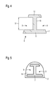
- FIG. 4 shows a core cross-section of an exemplary core tool
- FIG. 5 shows a cross-section of a semi-finished tube which is mounted on the core tool
- FIG. 6 shows a charging of a force for forming to the arrangement according to FIG. 5 by means of a vacuum
- FIG. 7 shows a charging of a force for forming to the arrangement according to FIG. 5 by means of a forming tool
- FIG. 8 shows a vanishing point projection of a frontal view of a further core tool
- FIG. 9 shows a cross-sectional view of a plastic foil tube with an intended cross-section produced according to the inventive method
- FIG. 10 shows a cross-sectional view of a plastic foil tube in a negative mold for forming to a further intended cross-section
- FIG. 11 shows a cross-sectional view of the plastic foil tube in a negative mold with the further intended cross-section.
- FIG. 1 shows a cross-section of a conventional thin walled tube as semi-finished tube 2 with a round cross-section 4 , respectively with a circular cross-section after the production by means of the blow extrusion method which might be folded plane 3 for transportation.
- This tube serves as semi-finished tube 2 for the production of a plastic foil tube 1 with an intended cross-section 6 which has a trapezoidal shape in the example shown in FIG. 2 .
- This intended cross-section 6 is denoted in the following as second intended cross-section 6 .
- FIG. 3 schematically shows forming steps of the semi-finished tube 1 of FIG. 1 into a first intended cross-section 5 and into the second intended cross-section 6 according to an embodiment of an inventive method.
- tubes that are denoted as semi-finished tubes 2 which were produced by means of the extrusion method or by means of the blow extrusion method (see FIG. 1 ) are formable into different geometries with appropriate intended cross-sections.
- the method might be divided into two forming steps.
- plastic foil tube 1 It is intended to produce a thin walled plastic foil tube 1 with the second intended cross-section 6 .
- the application of such a plastic foil tube 1 as a means for the production of fiber composite components requires such a tube with additional oversize crinkles for balancing possibly existing deviations in a cross-section of a fiber compound component due to production tolerances or local reinforcements.
- the semi-finished tube 2 is provided in a coiled form and mounted onto a core tool 7 , the cross-section 8 of which is shown in FIG. 4 , which is schematically depicted in FIG. 5 in a cross-sectional view.
- the core cross-section 8 is formed as a trapezoid alike the second intended cross-section 6 , but is provided with lateral recesses 9 which here are arranged symmetrically. It is easily imaginable that the core tool 7 is disposed perpendicular to the drawing plane and extends in this direction in a defined length. Also the recesses 9 run along this direction. By means of the recesses 9 a bar 10 is produced which is arranged in the middle, stands perpendicular with its lower end on a foot section 7 and is connected at its upper end orthogonally to a head section 12 . The recesses 9 have a recess height S. By means of the recesses 9 a circumference of the core cross-section 8 is enlarged.
- this circumference is longer, respectively larger than a circumference of the semi-finished tube cross-section.
- the ratio of the core cross-section 8 to the circumference of the semi-finished tube cross-section thereby has to be determined depending on the frictional coefficients of the core and the tube materials as well as on the circumference of the foil tube that has to be produced.
- the core tool might be made of plastic, e.g. of PA (polyamid), PTFE (polythtrafluouethelene), or metal or a combination of this or different materials.
- the tube might be composed of a polymer plastic material, for example.
- the core tool 7 is arranged inside an interior 14 of the semi-finished tube 2 .
- FIG. 6 shows the charging of a force F 1 for forming to the configuration according to FIG. 5 by means of a vacuum.
- the force F 1 is equal to the product of a pressure difference ⁇ p of an ambient pressure p 0 and in inner pressure p 1 in the interior 14 of the semi-finished tube and a product of the recess height S and a length of the recess 9 .
- the semi-finished tube 2 After pressing the semi-finished tube 2 on the core cross-section 8 the semi-finished tube 2 is heated to a predetermined forming temperature (here denoted as t 1 ) and temporarily maintained on this temperature for a predetermined time period.
- a predetermined forming temperature here denoted as t 1
- a force F 2 is chargeable by means of a forming tool 13 as schematically illustrated in FIG. 7 .
- the forming tool 13 consists in the shown example of two sliding rails which press the semi-finished tube 2 on both sides on the core cross-section 8 at a simultaneous heating and thereby produce a forming of the semi-finished tube 2 .
- FIG. 8 shows a vanishing point projection of the core tool 7 from which the longitudinal extension of the recesses 9 between the foot section 11 and the head section 12 becomes apparent.
- the semi-finished tube 2 After cooling down the semi-finished tube 2 which was formed in this way the semi-finished tube 2 is strippable off the core tool 7 in a further step. Thereby a supporting medium, e.g. pressurized air may be guided into the interior 14 , temporarily or for the duration of the whole demolding process.
- the formed semi-finished tube 2 formed in this way is now the plastic foil tube 1 with the first intended cross-section 5 which is shown in FIG. 9 cut to a predetermined end length in a three-dimensional cross-sectional view. Thereby sharp edges in the edge areas of foot section 11 and head section 12 are viewable.
- FIG. 10 shows a sectional view of a plastic foil tube 1 in a negative mold 21 of a forming tool 20 for forming into a further, namely the second intended cross-section 6 .
- the plastic foil tube 1 comprises foot crinkles 15 with a sharp edge.
- portions are viewable which protrude into the interior 14 and which have been produced by pressing into the recesses 9 of the core tool 7 .
- These portions comprise lower resection crinkles 16 and upper resection crinkles 18 as well as rounded inner resection crinkles 17 which are arranged on the portion that protrudes into the interior 14 .
- Sharp edged head crinkles 19 are arranged in the upper area of the plastic foil tube 1 .
- the negative mold 21 in the forming tool 20 comprises a cross-section corresponding to the second (in this example trapezoidal shape) intended cross-section 6 (see FIG. 2 ).
- the interior of the plastic foil tube 1 has the ambient pressure p 0 but is pressurized in the next step with a pressure p 1 which causes the portions that protrude into the interior 14 to attach to the walls of the negative mold 21 as is illustrated in FIG. 11 .
- the arrangement is heated to a predetermined forming temperature of the plastic foil tube 1 .
- the plastic foil tube 1 is plastically formed to the second intended cross-section 6 .
- This optionally second forming step in the negative mold serves inter alia for the removal of the crinkles 15 . . . 19 which have been produced in the first forming step on the core tool 7 .
- a direct forming of the flat packed semi-finished tube 2 ( FIGS. 1 and 3 ) to a geometry with sharp outer edges is not possible without the first forming step.
- the forming tool 20 for this second forming step is also imaginable for continuous method, by means of which the plastic foil tube 1 is pulled through the negative mold 21 , which thereby serves as a die with a predetermined velocity and is thereby formed to the second intended cross-section 6 .
- the invention is not limited to the specific method for producing a fiber compound component in aviation and aerospace as depicted in the figures.
- the geometry of the intended cross-sections is modifiable in various manners. It is possible to produce more than two intended cross-sections, for example in several forming steps.
- plastic foil tubes 1 with a respective intended cross-section 5 , 6 are used for the transport of liquid or gaseous media where only an ascertained installation space is available.
- the installation space is usable better.
- the invention relates to a method for producing a plastic foil tube 1 with an intended cross-section 5 , 6 that derives from a circular cross-section. It comprises the following method steps: mounting a semi-finished tube 2 on a core tool 7 ; charging the mounted semi-finished tube 2 with a predetermined force F 1 , F 2 to press the semi-finished tube 2 on a core cross-section 8 of the core tool 7 ; heating the semi-finished tube 2 to a predetermined forming temperature for a predetermined time period for the production of the plastic foil tube 1 with the intended cross-section 5 , 6 ; and stripping the plastic foil tube 1 which is formed in such a manner and cooled down off the core tool 7 .
Landscapes
- Engineering & Computer Science (AREA)
- Mechanical Engineering (AREA)
- Manufacturing & Machinery (AREA)
- Shaping Of Tube Ends By Bending Or Straightening (AREA)
- Moulding By Coating Moulds (AREA)
Abstract
Description
-
- good reproduction of curbs and edges with low radii.
- possibility to produce adapted tubes at face, thereby low transportation costs.
- the method according to the invention is suitable for a large spectrum of geometries, cross-sections, materials and wall thicknesses (about 30 μm . . . 4 mm, in particular in the area of 0.2 . . . 0.3 mm).
- the method according to the invention is partly automatable.
- the method according to the invention further gives a possibility for the production of cost effective and qualitatively high class fiber compound components, for example for aviation or aerospace.
- 1 plastic foil tube
- 2 semi-finished tube
- 3 transportation folding
- 4 circular cross-section
- 5 first intended cross-section
- 6 second intended cross-section
- 7 core tool
- 8 core cross-section
- 9 recess
- 10 bar
- 11 foot section
- 12 head section
- 13 forming tool
- 14 interior
- 15 foot crinkle
- 16 lower recess crinkle
- 17 inner recess crinkle
- 18 upper recess crinkle
- 19 head crinkle
- 20 forming tool
- 21 negative mold
- F1 . . . 2 force
- p0 . . . 1 pressure
- S recess height
- t1 temperature
Claims (28)
Priority Applications (1)
| Application Number | Priority Date | Filing Date | Title |
|---|---|---|---|
| US12/632,899 US9463590B2 (en) | 2008-12-11 | 2009-12-08 | Method for producing a plastic foil tube and a related plastic foil tube |
Applications Claiming Priority (2)
| Application Number | Priority Date | Filing Date | Title |
|---|---|---|---|
| US12162608P | 2008-12-11 | 2008-12-11 | |
| US12/632,899 US9463590B2 (en) | 2008-12-11 | 2009-12-08 | Method for producing a plastic foil tube and a related plastic foil tube |
Publications (2)
| Publication Number | Publication Date |
|---|---|
| US20100151169A1 US20100151169A1 (en) | 2010-06-17 |
| US9463590B2 true US9463590B2 (en) | 2016-10-11 |
Family
ID=42240887
Family Applications (1)
| Application Number | Title | Priority Date | Filing Date |
|---|---|---|---|
| US12/632,899 Expired - Fee Related US9463590B2 (en) | 2008-12-11 | 2009-12-08 | Method for producing a plastic foil tube and a related plastic foil tube |
Country Status (1)
| Country | Link |
|---|---|
| US (1) | US9463590B2 (en) |
Families Citing this family (3)
| Publication number | Priority date | Publication date | Assignee | Title |
|---|---|---|---|---|
| EP2871045A1 (en) | 2013-11-06 | 2015-05-13 | Airbus Operations GmbH | Arrangement and method for producing a composite material component |
| US10026843B2 (en) | 2015-11-30 | 2018-07-17 | Taiwan Semiconductor Manufacturing Co., Ltd. | Fin structure of semiconductor device, manufacturing method thereof, and manufacturing method of active region of semiconductor device |
| CN115535689B (en) * | 2022-10-18 | 2025-06-06 | 五行科技股份有限公司 | A reversing device and hose production line |
Citations (3)
| Publication number | Priority date | Publication date | Assignee | Title |
|---|---|---|---|---|
| US2837121A (en) | 1956-01-30 | 1958-06-03 | Fred T Roberts | Flexible hose and method and apparatus for making same |
| US6793871B1 (en) | 1998-09-16 | 2004-09-21 | Richter Guenter | Method and device for producing a large-volume container |
| US20050005987A1 (en) * | 2003-07-12 | 2005-01-13 | Hayes Frank F. | Method and apparatus for forming flared tube ends |
-
2009
- 2009-12-08 US US12/632,899 patent/US9463590B2/en not_active Expired - Fee Related
Patent Citations (3)
| Publication number | Priority date | Publication date | Assignee | Title |
|---|---|---|---|---|
| US2837121A (en) | 1956-01-30 | 1958-06-03 | Fred T Roberts | Flexible hose and method and apparatus for making same |
| US6793871B1 (en) | 1998-09-16 | 2004-09-21 | Richter Guenter | Method and device for producing a large-volume container |
| US20050005987A1 (en) * | 2003-07-12 | 2005-01-13 | Hayes Frank F. | Method and apparatus for forming flared tube ends |
Non-Patent Citations (2)
| Title |
|---|
| German Office Action, Sep. 18, 2013. |
| Yuan et al. "Control and use of wrinkles in tube hydroforming" J. of Mat. Proc. Tech. ,2007. * |
Also Published As
| Publication number | Publication date |
|---|---|
| US20100151169A1 (en) | 2010-06-17 |
Similar Documents
| Publication | Publication Date | Title |
|---|---|---|
| EP2539134B1 (en) | Continuous molding of thermoplastic laminates | |
| US8889050B2 (en) | Method for producing a fibre composite component for air and space technology | |
| JP5812782B2 (en) | Method and apparatus for manufacturing a highly curved stiffener with less wrinkling | |
| US10207466B2 (en) | Apparatus for forming thick thermoplastic composite structures | |
| KR102202254B1 (en) | Staggered bevel for continuous compression molding tooling dies | |
| US20200016796A1 (en) | Methods of making hybrid laminate and molded composite structures | |
| CN104690980B (en) | Thermoplastic composite support structure with integral fittings and method of manufacture | |
| KR20150053222A (en) | Laminated composite radius filler with geometric shaped filler element and method of forming the same | |
| US9463590B2 (en) | Method for producing a plastic foil tube and a related plastic foil tube | |
| US10293552B2 (en) | Heat shrinkable film tube and method for manufacturing hollow composite parts | |
| US20100151162A1 (en) | Method for producing an integral, reinforced fibre composite component as well as a hollow fibre composite component | |
| US11498293B2 (en) | Method and apparatus for forming a composite fuselage structure | |
| US11745441B2 (en) | Fiber-composite bicycle frame article formed on molded mandrel | |
| US9056428B2 (en) | Manufacturing method for hollow components made of fiber composite materials in tubular design, tubular film and manufacturing method for a tubular film | |
| EP3838542B1 (en) | METHOD AND DEVICE FOR FORMING A COMPOSITE TORSO STRUCTURE | |
| JP5968445B2 (en) | Compression molding of composite pseudo-isotropic flakes | |
| KR20220095194A (en) | Thermoplastic composite braided preform for elongated structural profile and method for manufacturing same | |
| WO1994003322A1 (en) | Molded laminate and method of producing the same | |
| Debnath et al. | Primary Manufacturing of Thermoplastic Polymer Matrix Composites | |
| JPH11170381A (en) | Manufacture of flanged tubular molded body of resin |
Legal Events
| Date | Code | Title | Description |
|---|---|---|---|
| AS | Assignment |
Owner name: AIRBUS OPERATIONS GMBH,GERMANY Free format text: ASSIGNMENT OF ASSIGNORS INTEREST;ASSIGNORS:DORAWA, TOBIAS;JACOB, TORBEN;REEL/FRAME:023924/0544 Effective date: 20091214 Owner name: AIRBUS OPERATIONS GMBH, GERMANY Free format text: ASSIGNMENT OF ASSIGNORS INTEREST;ASSIGNORS:DORAWA, TOBIAS;JACOB, TORBEN;REEL/FRAME:023924/0544 Effective date: 20091214 |
|
| STCF | Information on status: patent grant |
Free format text: PATENTED CASE |
|
| FEPP | Fee payment procedure |
Free format text: PAYOR NUMBER ASSIGNED (ORIGINAL EVENT CODE: ASPN); ENTITY STATUS OF PATENT OWNER: LARGE ENTITY |
|
| FEPP | Fee payment procedure |
Free format text: MAINTENANCE FEE REMINDER MAILED (ORIGINAL EVENT CODE: REM.); ENTITY STATUS OF PATENT OWNER: LARGE ENTITY |
|
| LAPS | Lapse for failure to pay maintenance fees |
Free format text: PATENT EXPIRED FOR FAILURE TO PAY MAINTENANCE FEES (ORIGINAL EVENT CODE: EXP.); ENTITY STATUS OF PATENT OWNER: LARGE ENTITY |
|
| STCH | Information on status: patent discontinuation |
Free format text: PATENT EXPIRED DUE TO NONPAYMENT OF MAINTENANCE FEES UNDER 37 CFR 1.362 |
|
| FP | Lapsed due to failure to pay maintenance fee |
Effective date: 20201011 |