US9461802B2 - Apparatus and method for transmitting HARQ ACK/NACK - Google Patents
Apparatus and method for transmitting HARQ ACK/NACK Download PDFInfo
- Publication number
- US9461802B2 US9461802B2 US14/552,402 US201414552402A US9461802B2 US 9461802 B2 US9461802 B2 US 9461802B2 US 201414552402 A US201414552402 A US 201414552402A US 9461802 B2 US9461802 B2 US 9461802B2
- Authority
- US
- United States
- Prior art keywords
- ack
- nack
- harq
- serving cell
- harq ack
- Prior art date
- Legal status (The legal status is an assumption and is not a legal conclusion. Google has not performed a legal analysis and makes no representation as to the accuracy of the status listed.)
- Active, expires
Links
- 238000000034 method Methods 0.000 title claims abstract description 66
- 101000741965 Homo sapiens Inactive tyrosine-protein kinase PRAG1 Proteins 0.000 title claims abstract description 35
- 102100038659 Inactive tyrosine-protein kinase PRAG1 Human genes 0.000 title claims abstract description 35
- 230000005540 biological transmission Effects 0.000 claims abstract description 121
- 230000004044 response Effects 0.000 claims abstract description 8
- 230000002776 aggregation Effects 0.000 claims description 24
- 238000004220 aggregation Methods 0.000 claims description 24
- 230000002085 persistent effect Effects 0.000 claims 2
- 238000010586 diagram Methods 0.000 description 19
- 238000004891 communication Methods 0.000 description 18
- 239000000969 carrier Substances 0.000 description 15
- 230000008569 process Effects 0.000 description 7
- 238000001514 detection method Methods 0.000 description 5
- 230000009977 dual effect Effects 0.000 description 5
- 238000013468 resource allocation Methods 0.000 description 5
- 230000004048 modification Effects 0.000 description 4
- 238000012986 modification Methods 0.000 description 4
- 230000008859 change Effects 0.000 description 3
- 125000004122 cyclic group Chemical group 0.000 description 3
- 230000000694 effects Effects 0.000 description 3
- 238000013507 mapping Methods 0.000 description 3
- 230000011664 signaling Effects 0.000 description 3
- 238000012937 correction Methods 0.000 description 2
- 238000013461 design Methods 0.000 description 2
- 238000007726 management method Methods 0.000 description 2
- 102100036409 Activated CDC42 kinase 1 Human genes 0.000 description 1
- 230000006978 adaptation Effects 0.000 description 1
- 230000008901 benefit Effects 0.000 description 1
- 230000001186 cumulative effect Effects 0.000 description 1
- 238000005516 engineering process Methods 0.000 description 1
- 239000011159 matrix material Substances 0.000 description 1
- 238000001228 spectrum Methods 0.000 description 1
- 230000001360 synchronised effect Effects 0.000 description 1
Images


Classifications
-
- H—ELECTRICITY
- H04—ELECTRIC COMMUNICATION TECHNIQUE
- H04L—TRANSMISSION OF DIGITAL INFORMATION, e.g. TELEGRAPHIC COMMUNICATION
- H04L5/00—Arrangements affording multiple use of the transmission path
- H04L5/003—Arrangements for allocating sub-channels of the transmission path
- H04L5/0053—Allocation of signaling, i.e. of overhead other than pilot signals
- H04L5/0055—Physical resource allocation for ACK/NACK
-
- H—ELECTRICITY
- H04—ELECTRIC COMMUNICATION TECHNIQUE
- H04J—MULTIPLEX COMMUNICATION
- H04J4/00—Combined time-division and frequency-division multiplex systems
-
- H—ELECTRICITY
- H04—ELECTRIC COMMUNICATION TECHNIQUE
- H04L—TRANSMISSION OF DIGITAL INFORMATION, e.g. TELEGRAPHIC COMMUNICATION
- H04L1/00—Arrangements for detecting or preventing errors in the information received
- H04L1/12—Arrangements for detecting or preventing errors in the information received by using return channel
- H04L1/16—Arrangements for detecting or preventing errors in the information received by using return channel in which the return channel carries supervisory signals, e.g. repetition request signals
- H04L1/18—Automatic repetition systems, e.g. Van Duuren systems
- H04L1/1812—Hybrid protocols; Hybrid automatic repeat request [HARQ]
-
- H—ELECTRICITY
- H04—ELECTRIC COMMUNICATION TECHNIQUE
- H04L—TRANSMISSION OF DIGITAL INFORMATION, e.g. TELEGRAPHIC COMMUNICATION
- H04L1/00—Arrangements for detecting or preventing errors in the information received
- H04L1/12—Arrangements for detecting or preventing errors in the information received by using return channel
- H04L1/16—Arrangements for detecting or preventing errors in the information received by using return channel in which the return channel carries supervisory signals, e.g. repetition request signals
- H04L1/18—Automatic repetition systems, e.g. Van Duuren systems
- H04L1/1829—Arrangements specially adapted for the receiver end
- H04L1/1854—Scheduling and prioritising arrangements
-
- H—ELECTRICITY
- H04—ELECTRIC COMMUNICATION TECHNIQUE
- H04L—TRANSMISSION OF DIGITAL INFORMATION, e.g. TELEGRAPHIC COMMUNICATION
- H04L5/00—Arrangements affording multiple use of the transmission path
- H04L5/0001—Arrangements for dividing the transmission path
- H04L5/0003—Two-dimensional division
- H04L5/0005—Time-frequency
- H04L5/0007—Time-frequency the frequencies being orthogonal, e.g. OFDM(A), DMT
- H04L5/001—Time-frequency the frequencies being orthogonal, e.g. OFDM(A), DMT the frequencies being arranged in component carriers
-
- H—ELECTRICITY
- H04—ELECTRIC COMMUNICATION TECHNIQUE
- H04L—TRANSMISSION OF DIGITAL INFORMATION, e.g. TELEGRAPHIC COMMUNICATION
- H04L5/00—Arrangements affording multiple use of the transmission path
- H04L5/0091—Signaling for the administration of the divided path
- H04L5/0096—Indication of changes in allocation
- H04L5/0098—Signalling of the activation or deactivation of component carriers, subcarriers or frequency bands
-
- H—ELECTRICITY
- H04—ELECTRIC COMMUNICATION TECHNIQUE
- H04L—TRANSMISSION OF DIGITAL INFORMATION, e.g. TELEGRAPHIC COMMUNICATION
- H04L5/00—Arrangements affording multiple use of the transmission path
- H04L5/14—Two-way operation using the same type of signal, i.e. duplex
-
- H—ELECTRICITY
- H04—ELECTRIC COMMUNICATION TECHNIQUE
- H04W—WIRELESS COMMUNICATION NETWORKS
- H04W72/00—Local resource management
- H04W72/20—Control channels or signalling for resource management
- H04W72/23—Control channels or signalling for resource management in the downlink direction of a wireless link, i.e. towards a terminal
-
- H—ELECTRICITY
- H04—ELECTRIC COMMUNICATION TECHNIQUE
- H04W—WIRELESS COMMUNICATION NETWORKS
- H04W88/00—Devices specially adapted for wireless communication networks, e.g. terminals, base stations or access point devices
- H04W88/02—Terminal devices
Definitions
- the present disclosure relates to wireless communication, and more particularly, to a method and apparatus for transmitting an HARQ ACK/NACK.
- ARQ Automatic repeat request
- HARQ hybrid automatic repeat request
- FEC Forward Error Correction
- a receiver that utilizes HARQ generally attempts an error correction for a received data signal and determines whether a retransmission needs to be performed by using an error detection code.
- error detection code Cyclic Redundancy Check (CRC) scheme may be used. If data signal error is not detected from the detection process of CRC scheme, the receiver determines that a decoding process for the data signal is successful.
- CRC Cyclic Redundancy Check
- the receiver transmits an Acknowledgement (ACK) signal to a transmitter. If data signal error is detected from the detection process of CRC scheme, the receiver determines that a decoding process for the data signal is not successful. In this case, the receiver transmits a Not-Acknowledgement (NACK) signal to a transmitter. If the transmitter receives the NACK signal, the transmitter may retransmit the data signal.
- ACK Acknowledgement
- NACK Not-Acknowledgement
- a wireless communication system may support Frequency Division Duplex (FDD) scheme and Time Division Duplex (TDD) scheme.
- FDD Frequency Division Duplex
- TDD Time Division Duplex
- an uplink transmission and a downlink transmission may be simultaneously performed in a cell because a carrier frequency for an uplink (UL) transmission is different from a carrier frequency for a downlink (DL) transmission exists.
- UL uplink
- DL downlink
- TDD Time Division Duplex
- a base station and a user equipment perform switching operations between a transmission mode and a reception mode because the same carrier is used for both an uplink transmission and a downlink transmission.
- a Special Subframe may be added to provide a guard time for switching between the transmission mode and the reception mode.
- the Special Subframe may include Downlink Pilot Time Slot (DwPTS), Guard Period (GP), and Uplink Pilot Time Slot (UpPTS).
- DwPTS Downlink Pilot Time Slot
- GP Guard Period
- UpPTS Uplink Pilot Time Slot
- resource amounts for the uplink transmission and resource amounts for the downlink transmission may be asymmetrically assigned through various uplink (UL)-downlink (DL) configurations.
- each of scattered bands has been configured to satisfy basic requirements to operate an independent system and a carrier aggregation (CA) scheme, which aggregates various frequency bands into one system, has been adopted.
- CA carrier aggregation
- each frequency band or carrier capable of an independent operation may be defined as a component carrier (CC).
- CC component carrier
- ACK/NACK signals corresponding to a plurality of component carriers (CCs) need to be transmitted.
- TDD-FDD CA Time Division Duplex
- FDD-FDD CA Frequency Division Duplex
- CA Carrier Aggregation
- the TDD-FDD CA is referred to as a TDD-FDD joint operation.
- a first serving cell is configured as TDD
- a second serving cell is configured as FDD
- a large number of DL subframes of the second serving cell may exist in association with a single UL subframe of the first serving cell. Therefore, there is desire for a method of effectively transmitting a HARQ ACK/NACK, for the TDD-FDD CA.
- a control channel of the first serving cell that is, a Physical Uplink Control Channel (PUCCH)
- PUCCH Physical Uplink Control Channel
- Exemplary embodiments of the present invention provide a method and apparatus for transmitting a HARQ ACK/NACK, and a method and apparatus for receiving a HARQ ACK/NACK.
- Exemplary embodiments of the present invention provide a method and apparatus for bundling a HARQ ACK/NACK associated with a new associated subframe with a HARQ ACK/NACK associated with a legacy associated subframe.
- An exemplary embodiment of the present invention provides a method of communicating control information between a base station and a user equipment (UE), the method including: establishing a Radio Resource Control (RRC) connection with the base station through a first serving cell, the first serving cell supporting a Time Division Duplex (TDD) mode; receiving an RRC message from the base station through the first serving cell, the RRC message including carrier aggregation (CA) configuration information, the CA configuration information including information of a second serving cell supporting a Frequency Division Duplex (FDD) mode, and the first serving cell and the second serving cell being aggregated by a TDD-FDD CA scheme; recognizing a 2-bit downlink (DL) downlink assignment index (DAI) field configured in a DL downlink control information (DCI) format, the DL DCI format indicating a Physical Downlink Shared Channel (PDSCH) transmission on the second serving cell, and the 2-bit DL DAI field indicating that ten downlink subframes for the second serving cell are associated with one uplink subframe; receiving, at
- An exemplary embodiment of the present invention provides a method of communicating control information between a base station and a user equipment (UE), the method including: establishing a Radio Resource Control (RRC) connection with the UE through a first serving cell, the first serving cell supporting a Time Division Duplex (TDD) mode; transmitting an RRC message to the UE through the first serving cell, the RRC message including carrier aggregation (CA) configuration information, the CA configuration information including information of a second serving cell supporting a Frequency Division Duplex (FDD) mode, and the first serving cell and the second serving cell being aggregated by a TDD-FDD CA scheme; configuring a 2-bit downlink (DL) downlink assignment index (DAI) field in a DL downlink control information (DCI) format, the DL DCI format indicating a Physical Downlink Shared Channel (PDSCH) transmission on the second serving cell, and the 2-bit DL DAI field indicating that ten downlink subframes for the second serving cell are associated with one uplink subframe; transmitting,
- a base station and a terminal may implement an effective HARQ ACK/NACK transmitting method.
- FIG. 1 illustrates a wireless communication system according to an exemplary embodiment of the present invention.
- FIG. 2 illustrates an example of a protocol structure for supporting a multi-carrier system according to an exemplary embodiment of the present invention.
- FIG. 3 illustrates an example of a radio frame structure according to an exemplary embodiment of the present invention.
- FIG. 4 illustrates a case of an inter-band CA of serving cells having different TDD UL-DL configurations.
- FIG. 5 illustrates an example of a deployment scenario according to an exemplary embodiment of the present invention.
- FIG. 6 illustrates an example of an FDD-TDD CA scheme according to an exemplary embodiment of the present invention.
- FIG. 7 illustrates examples of capabilities of a terminal for a TDD-FDD CA according to an exemplary embodiment of the present invention.
- FIG. 8 illustrates an example of a DL HARQ timing when a terminal for which a TDD-FDD CA is configured operates based on self-scheduling.
- FIG. 9 illustrates an example of a DL HARQ timing when a terminal for which a TDD-FDD CA is configured operates based on cross-carrier scheduling.
- FIGS. 10 and 11 are diagrams illustrating a new DL HARQ timing according to an exemplary embodiment of the present invention.
- FIG. 12 is a diagram illustrating a legacy HARQ ACK/NACK that is bundled with a new HARQ ACK/NACK according to an exemplary embodiment of the present invention.
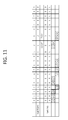
- FIG. 13 is a diagram illustrating a method of bundling HARQ ACK/NACKs based on a Downlink Assignment Index (DAI) according to an exemplary embodiment of the present invention.
- DAI Downlink Assignment Index
- FIG. 14 is a diagram illustrating HARQ ACK/NACK bundling according to an exemplary embodiment of the present invention.
- FIG. 15 is a diagram illustrating HARQ ACK/NACK bundling according to another exemplary embodiment of the present invention.
- FIG. 16 is a diagram illustrating HARQ ACK/NACK bundling according to another exemplary embodiment of the present invention.
- FIG. 17 is a diagram illustrating a case in which an identical DAI value is applied to subframes that are bundled according to an exemplary embodiment of the present invention.
- FIG. 18 is a flowchart illustrating a HARQ ACK/NACK transmission method according to an exemplary embodiment of the present invention.
- FIG. 19 illustrates an example of mapping a PUCCH to physical RBs.
- FIG. 20 is a block diagram illustrating a terminal and a base station according to an exemplary embodiment of the present invention.
- first, second, A, B, (a), (b), and the like may be used herein to describe elements in the description herein. The terms are used to distinguish one element from another element. Thus, the terms do not limit the element, an arrangement order, a sequence or the like. It will be understood that when an element is referred to as being “on”, “connected to” or “coupled to” another element, it can be directly on, connected or coupled to the other element or intervening elements may be present.
- an operation performed in a wireless communication network may be performed in a process of controlling a network and transmitting data by a system that controls a wireless network (e.g., a base station) or may be performed in a user equipment connected to the wireless communication network.
- a system that controls a wireless network e.g., a base station
- a user equipment connected to the wireless communication network.
- FIG. 1 is a diagram illustrating a wireless communication system according to an exemplary embodiment of the present invention.
- a wireless communication system 10 is widely deployed in order to provide diverse telecommunication services, such as voice and packet data.
- a wireless communication system includes at least one base station 11 (BS).
- Each BS 11 provides telecommunication service to certain cells 15 a , 15 b , and 15 c .
- a cell may again be divided into multiple sectors.
- User equipment 12 may be located at a certain location or mobile, and may also be referred to as different terms, including UE (user equipment), MT (mobile terminal), UT (user terminal), SS (subscriber station), wireless device, PDA (personal digital assistant), wireless modem, and handheld device.
- a base station 11 may also be referred to as eNB (evolved-NodeB), BTS (Base Transceiver System), Access Point, femto base station, Home nodeB, and relay.
- a cell inclusively refers to various coverage areas, such as mega cell, macro cell, micro cell, pico cell, and femto cell.
- the term downlink refers to communication from a base station 11 to a UE 12
- the term uplink refers to communication from a UE 12 to a base station 11
- a transmitter may be part of a base station 11
- a receiver may be part of a UE 12
- a transmitter may be part of a UE 12 and a receiver may be part of a base station 11 .
- Uplink transmission and downlink transmission can use either TDD (Time Division Duplex), which uses different time locations for transmissions, or FDD (Frequency Division Duplex), which uses different frequencies for transmissions.
- TDD Time Division Duplex
- FDD Frequency Division Duplex
- CA Carrier Aggregation
- CC Component Carrier
- Each component carrier is defined by bandwidth and center frequency.
- CA is introduced to support increasing throughput, to prevent cost increase due to the introduction of the wideband radio frequency and to ensure the compatibility with the existing system. For example, if five component carriers are allocated as granularity that has a carrier unit with 20 MHz bandwidth, it can support 100 MHz bandwidth at maximum.
- CA may be divided as contiguous carrier aggregation, which is made among continuous CCs, and non-contiguous carrier aggregation, which is made among non-continuous CCs.
- the number of carriers aggregated between uplink and downlink may be configured differently. It is referred to as symmetric aggregation when there are equal number of downlink CCs and uplink CCs, and it is referred to as asymmetric aggregation when the number of downlink CCs and the number of uplink CCs are not equal.
- the size of component carriers may be different. For example, if five component carriers are used to form 70 MHz band, 5 MHz component carrier (carrier #0)+20 MHz component carrier (carrier #1)+20 MHz component carrier (carrier #2)+20 MHz component carrier (carrier #3)+5 MHz component carrier (carrier #4) may be aggregated together.
- a multiple carrier system includes the system that supports carrier aggregation.
- Contiguous CA and/or non-contiguous CA may be used in the multiple carrier system; in addition, both symmetric aggregation and asymmetric aggregation may be used in the multiple carrier system as well.
- a serving cell may be defined as a component frequency band based on multiple CC system which may be aggregated by CA.
- a serving cell may include a primary serving cell (PCell) and a secondary serving cell (SCell).
- a PCell means a serving cell which provides security input and Non-Access Stratum (NAS) mobility information on Radio Resource Control (RRC) establishment or re-establishment state.
- NAS Non-Access Stratum
- At least one cell may be used together with a PCell to form an aggregation of serving cells, the cell used with a PCell is referred to as an SCell.
- An aggregation of serving cells which configured for a user equipment may include one PCell, or one PCell together with at least one SCell.
- Downlink component carrier corresponding to a PCell refers to Downlink (DL) Primary Component Carrier (PCC), and uplink component carrier corresponding to a PCell refers to Uplink (UL) PCC.
- downlink component carrier corresponding to an SCell refers to a DL Secondary Component Carrier (SCC)
- an uplink component carrier corresponding to an SCell refers to a UL SCC. Only DL CC or UL CC may correspond to a serving cell, or a DL CC and an UL CC together may correspond to a serving cell.
- FIG. 2 is a diagram illustrating an example of a protocol structure for supporting a multi-carrier system according to an exemplary embodiment of the present invention.
- common Medium Access Control (MAC) entity 210 manages physical layer 220 which uses a plurality of carriers.
- the MAC management message transmitting through a certain carrier, may be applied to other carriers. That is, the MAC management message is a message which controls other carriers including the certain carrier mentioned above.
- a physical layer 220 may be operated by the Time Division Duplex (TDD) and/or the Frequency Division Duplex (FDD).
- TDD Time Division Duplex
- FDD Frequency Division Duplex
- a Physical Downlink Control Channel informs to a UE with regard to resource allocation of a Paging Channel (PCH) and a Downlink Shared Channel (DL-SCH), and a Hybrid Automatic Repeat Request (HARQ) information related to a DL-SCH.
- the PDCCH may carry uplink grant which informs a resource allocation of uplink transmission to a UE.
- the DL-SCHO is mapping to a Physical Downlink Shared Channel (PDSCH).
- a Physical Control Format Indicator Channel (PCFICH), which transmits every sub-frame, informs the number of OFDM symbols used on the PDCCHs to a user equipment.
- a Physical Hybrid ARQ Indicator Cannel (PHICH), as a DL channel, carries the HARQ ACK/NACK signals as a response to uplink transmission.
- Physical Uplink Control Channel (PUCCH) may carry UL controlling information such as ACK (Acknowledgement)/NACK (Non-acknowledgement) or Channel Status Information (CSI) which includes Channel Quality Indicator (CQI), Precoding Matrix Index (PMI), Precoding Type Indicator (PTI) or Rank Indication (RI).
- the Physical Uplink Shared Channel (PUSCH) carries the Uplink Shared Channel (UL-SCH).
- the Physical Random Access Channel (PRACH) carries random access preamble.
- a plurality of the PDCCH may be transmitted in the controlled region, and a user equipment can monitor a plurality of the PDCCH.
- the PDCCH is transmitted on either one Control Channel Element (CCE) or an aggregation of several consecutive CCEs.
- CCE is a logical allocation unit used to provide PDCCH with a code rate based on the state of radio channel.
- the CCE corresponds to a plurality of Resource Element Groups.
- the format of the PDCCH and the number of available bits for the PDCCH are determined according to the relationship between the number of CCEs and a code rate provided by the CCEs.
- DCI Downlink Control Information
- DCI formats such as format 0 used for the PUSCH scheduling in uplink cell, format 1 used for one PDSCH codeword scheduling in one cell, format 1A used for compact scheduling of one PDSCH codeword, format 2 used for the PDSCH scheduling in closed-loop spartial multiplexing mode, format 2B used for the PDSCH scheduling in open-loop spartial multiplexing mode, format 2B used in the transmission mode 8, format 2C used in the transmission mode 9, format 2D used in the transmission mode 10, format 3 and 3A used for the uplink transmission of TPC commands for the PUCCH and the PUSCH, and format 4 used for the PUSCH scheduling in the uplink multi-antenna port transmission cell.
- DCI formats such as format 0 used for the PUSCH scheduling in uplink cell, format 1 used for one PDSCH codeword scheduling in one cell, format 1A used for compact scheduling of one PDSCH codeword, format 2 used for the PDSCH scheduling in closed-loop spartial multiplexing mode, format 2B used for the PDSCH scheduling in
- Each field of DCI is sequentially mapped to n number of information bits a 0 or a n-1 .
- the DCI is mapped to a total length of 44 bits of information bits, each field of DCI is mapped sequentially to a 0 or a 43 .
- DCI formats 0, 1A, 3, 3A may have the same payload size.
- DCI format 0, 4 may be referred to as the Uplink grant (UL grant).
- Cross-carrier scheduling is a scheduling method capable of performing resource allocation of a PDSCH transmitted by using a different carrier through a PDCCH transmitted through a specific CC and/or resource allocation of a PUSCH transmitted by using another CC other than a CC basically linked to the specific CC. That is, the PDCCH and the PDSCH may be transmitted through different DL CCs, and the PUSCH may be transmitted through a UL CC other than a UL CC linked to a DL CC on which a PDCCH including a UL grant is transmitted.
- a user equipment During cross-carrier scheduling, a user equipment only receives scheduling information (such as UL grant) through a serving cell (or CC).
- scheduling cell or CC
- scheduling cell or CC
- scheduled cell or CC
- Scheduling cell may refer to ordering cell
- scheduled cell may refer to following serving cell. For example, a scheduled cell may be scheduled by a scheduling cell. Scheduling information for the scheduled cell may be received through the scheduling cell.
- a carrier indicator is necessary to report which DL CC/UL CC was used to transmit the PDCCH/EPDCCH which indicates the PDSCH/PUSCH transmission.
- a field including the carrier indicator is hereinafter called a carrier indication field (CIF).
- configuration of CIF may mean that configuration of cross-carrier scheduling.
- the aforementioned cross-carrier scheduling may be classified into the DL cross-carrier scheduling and UL cross-carrier scheduling.
- the DL cross-carrier scheduling implies a case where the CC for transmitting the PDCCH/EPDCCH including resource allocation information for the PDSCH transmission and other information is different from a CC for transmitting the PDSCH.
- the UL cross-carrier scheduling implies a case where a CC for transmitting the PDCCH/EPDCCH including a UL grant for the PUSCH transmission is different from the DL CC linked to the UL CC for transmitting the PUSCH.
- FIG. 3 is a diagram illustrating an example of a radio frame structure according to an exemplary embodiment of the present invention.
- the diagram illustrates a FDD radio frame structure and a TDD radio frame structure.
- one radio frame includes 10 subframes, and one subframe includes 2 consecutive slots.
- both carrier used for UL transmission and carrier used for DL transmission exist, and UL transmission and DL transmission may be performed simultaneously in one cell.
- UL transmission and DL transmission can always distinguished in time. Because a same carrier is used for both UL transmission and DL transmission, a base station and user equipment repeatedly switches between the transmission mode and the reception mode.
- special subframe may be placed to provide a guard time which is for switching mode between the transmission and the reception.
- Special subframe includes a downlink pilot time slot (DwPTS), a guard period (GP), and an uplink pilot time slot (UpPTS).
- DwPTS is used in the UE for initial cell search, synchronization, or channel estimation.
- the UpPTS is used in the BS for channel estimation and uplink transmission synchronization of the UE.
- the GP is needed to avoid interference between an uplink and a downlink, and during the GP, no UL transmission and DL transmission occurs.
- Table 2 shows an example of UL/DL configuration of radio frame.
- UL/DL configuration defines reserved subframe for UL transmission or reserved subframe for DL transmission. That is, UL/DL configuration informs the rules how the uplink and the downlink are allocated (or reserved) in every subframe of one radio frame.
- each UL-DL configuration has a different number and position of DL subframe and UL subframe in one radio frame. Through diverse UL-DL configuration, the amount of resource allocated to UL/DL transmission may be given asymmetrically. To avoid severe interference between UL and DL among cells, neighboring cells generally have same UL-DL configuration.
- the point changing from DL to UL or the point changing from UL to DL is referred to as the switching point.
- the switch-point periodicity which is either 5 ms or 10 ms, means a repeating period of the same changing aspect between the UL subframe and DL subframe. For example, referring to the UL/DL configuration 0, subframe from 0 to 4 changes D ⁇ S ⁇ U ⁇ U ⁇ U, subframe from 5 to 9 changes, as same as before, D ⁇ S ⁇ U ⁇ U ⁇ U. Since one subframe is 1 ms, the switch-point periodicity is 5 ms. That is, the switch-point periodicity is shorter than the length of one radio frame (10 ms), the changing aspect in the radio frame is repeated for one time.
- the UL-DL configuration in above Table 2 may be transmitted from a base station to a user equipment through system information.
- the base station may inform a UL/DL allocation status change in a radio frame to a UE by transmitting the index of the UL/DL configuration whenever the UL/DL configuration changes.
- the UL/DL configuration may be control information which is transmitted to every UE in the cell through broadcast channel.
- a base station transmits a DL grant, which is PDSCH scheduling information, to a terminal through a PDCCH or an EPDCCH, and transmits a PDSCH. Then, the terminal transmits a HARQ Acknowledgement/Non-acknowledgement (ACK/NACK) with respect to a DL-SCH Transport Block (TB) received through the PDSCH, trough a PUCCH at a predetermined timing.
- HARQ HARQ Acknowledgement/Non-acknowledgement
- TB DL-SCH Transport Block
- HARQ refers to an operation that receives a HARQ ACK/NACK with respect to a DL transmission from the terminal, and executes a DL retransmission or a new transmission.
- HARQ refers to an operation that transmits a HARQ ACK/NACK with respect to a DL transmission to the base station, and receives a DL retransmission or a new transmission.
- the terminal when a terminal detects a PDSCH transmission for the corresponding terminal from a subframe n ⁇ 4, the terminal transmits a HARQ response in a subframe n.
- the terminal transmits a HARQ response in a subframe n.
- DL HARQ ACK/NACK timings may be listed as shown in Table 3.
- n denotes a subframe number
- n ⁇ k denotes an index of a subframe that is k subframes before from an n th subframe, and indicates a DL subframe (that is, a DL HARQ timing) associated with a current subframe.
- the associated DL subframe indicates a subframe that delivers a PDSCH which is the basis of the determination on a HARQ ACK/NACK signal.
- M denotes the number of elements of a set K defined in table 3, and indicates the number of DL subframes associated with the n th subframe, or a bundling window size.
- DL subframes (or DL HARQ timings) associated with the subframe 2 of the corresponding serving cell are a subframe 5 (2-k 0 ) and a subframe 6 (2-k 1 ) of a previous radio frame.
- FIG. 4 illustrates a case of an inter-band CA of serving cells having different TDD UL-DL configurations.
- component carriers that configure a CA with a terminal are CC1 and CC2, the CC1 may be configured as UL-DL configuration #1 and CC2 may be configured as UL-DL configuration #2, for the purpose of traffic adaptation (semi-static) and avoidance of interference between heterogeneous networks.
- traffic adaptation for example, to avoid an interference issue with other TDD systems (for example, TDS-CDMA, WiMAX, and the like) that co-exist in an identical band, different UL-DL configurations may be required in an inter-band CA.
- a UL-DL configuration of the PCell is a DL reference UL-DL configuration.
- the DL reference UL-DL configuration indicates a UL-DL configuration used as a reference for a DL HARQ timing of a serving cell.
- a DL reference UL-DL configuration for the SCell is as shown in the following Table 4.
- the DL reference UL-DL configuration for the SCell may be indicated.
- the DL reference UL-DL configuration for the SCell applies a DL HARQ timing based on the DL reference UL-DL configuration for Set 1. In this instance, it is irrespective of a scheduling method.
- self-scheduling is set for a terminal
- the pair of the PCell UL-DL configuration and the SCell UL-DL configuration belongs to Set 2 or Set 3
- a DL reference UL-DL configuration of Set 2 or Set 3 is used.
- self-scheduling is set for the terminal, it indicates that the terminal is not set to monitor a PDCCH/EPDCCH of another serving cell for scheduling of a corresponding serving cell.
- cross-carrier scheduling is set for a terminal
- the pair of the PCell UL-DL configuration and the SCell UL-DL configuration belongs to Set 4 or Set 5
- a DL reference UL-DL configuration of Set 4 or Set 5 is used.
- cross-carrier scheduling is set for the terminal, it indicates that the terminal is set to monitor a PDCCH/EPDCCH of another serving cell for scheduling of a corresponding serving cell.
- the DL reference UL-DL configuration of Set 1 is applied when a corresponding pair is satisfied, irrespective of whether a Carrier Indicator Field (CIF) indicating a carrier associated with scheduling is configured.
- CIF Carrier Indicator Field
- Set 2 and Set 3 are applied to only a terminal for which a CIF is not configured
- Set 4 and Set 5 are applied to only a terminal for which a CIF is configured.
- An ACK/NACK signal with respect to a PDCCH/EPDCCH that indicates a PDSCH or SPS release corresponding to each of a plurality of serving cells of a CA may be transmitted at the above described HARQ timing.
- FIG. 5 illustrates an example of a deployment scenario according to an embodiment of the present invention.
- a plurality of macro cells and a plurality of small cells may be disposed, having an identical frequency or adjacent frequencies.
- a deployment scenario in which a plurality of outdoor small cells use a frequency band identical to a frequency band of macro cells (b) A deployment scenario in which a plurality of small cells use an identical frequency band, macro cells use a frequency band adjacent to the frequency band of the small cells, all of the macro cells have an identical UL-DL configuration, and the small cells may adjust a UL-DL configuration
- FIG. 6 is a diagram illustrating an example of an FDD-TDD CA method application according to an exemplary embodiment of the present invention.
- wireless communication service can only be received through the TDD band
- wireless communication service can only be received through the FDD band
- wireless communication service may be received through the FDD and the TDD bands, and also the CA based wireless communication service is provided through the TDD band carrier and the FDD band carrier.
- the FDD base station and the TDD base station is co-located (for example, CA scenarios 1 through 3), or the FDD base station and the TDD based station is not co-located, but connected through the ideal backhaul (for example, CA scenario 4).
- the FDD base station and the TDD base station is not co-located, and connected through non-ideal backhaul (for example, small cell scenario 2a, 2b, and macro-macro scenario).
- non-ideal backhaul for example, small cell scenario 2a, 2b, and macro-macro scenario.
- the TDD base station and the FDD base station is connected through the ideal backhaul and the TDD cell and the FDD cell is operated as synchronized.
- a UE supporting the FDD-TDD CA may access to the legacy FDD single mode carrier and the legacy TDD single mode carrier.
- the legacy FDD UEs and the UEs supporting the TDD-FDD CA may camp on and be connected to the FDD carrier which is the part of the aforementioned FDD/TDD network.
- the legacy TDD UEs and the UEs supporting the TDD-FDD CA may camp on and be connected to the TDD carrier which is the part of the aforementioned FDD/TDD joint operation network.
- a network architecture enhancement in order to facilitate the FDD-TDD CA for example, with regard to the non-ideal backhaul, may be considered.
- keeping the minimal network architecture changes should be considered since it is still essential in operator's perspective.
- FIG. 7 is examples of UE capabilities for the TDD-FDD CA according to an exemplary embodiment of the present invention.
- (a) indicates that a UE is supporting the CA between the TDD carrier and the FDD carrier; (b) indicates that a UE is supporting the CA between the TDD carrier and the FDD DL carrier; and (c) indicates that a UE is supporting the CA between the TDD carrier with a DL subframe and the FDD carrier.
- a UE may support different types of the TDD-FDD CA, and further, it may perform simultaneous reception (that is, DL aggregation) from the FDD and TDD carriers. Secondly, a UE may perform simultaneous transmission (that is, UL aggregation) from the FDD and TDD carriers, and thirdly, a UE may perform simultaneous transmission and reception (that is, full duplex) from the FDD and TDD carriers.
- a maximum number of aggregated Component Carriers may be, for example, 5.
- an aggregation of different UL-DL configurations for TDD carriers of different bands may be supported.
- the FDD-TDD CA-capable terminal may support the TDD-FDD DL CA and may not support the TDD-FDD UL CA.
- the FDD-TDD CA-capable terminal may support at least the TDD-FDD DL CA, but may or may not support the TDD-FDD UL CA.
- a UE may configure a dual connectivity through two or more base stations among base stations that may include at least one serving cell.
- a dual connectivity is an operation that the UE utilizes wireless resources provided by at least two different network points (for example, a macro base station or a small base station) in RRC CONNECTED mode.
- those abovementioned two different network points may be connected by a non-ideal backhaul.
- one of those abovementioned two different network points may refer to a macro base station (or a master base station or an anchor base station), remaining network points may refer to small base stations (or secondary base stations or assisting base stations, or slave base stations).
- a UE may support a TDD-FDD joint operation when the CA and/or dual connectivity is configured to the UE.
- aspects of the present invention will be explained based on a case where a UE configured to the CA, but aspects of the present invention may be applied to a case of a UE configured to the dual connectivity.
- the TDD-FDD CA may include an environment in which a PCell operates as TDD and an SCell operates as FDD.
- the environment is irrespective of a scheduling scheme, but has a high probability of being provided when self-scheduling is used.
- a DL HARQ timing to be applied to an SCell based on a relationship with a PCell which is a PUCCH transmission serving cell will be described.
- FIG. 8 illustrates an example of a DL HARQ timing when a terminal for which a TDD-FDD CA is configured operates based on self-scheduling.
- FIG. 8 corresponds to a case in which a PCell is configured as TDD UL-DL configuration 1, and an SCell is configured as FDD.
- an existing FDD DL HARQ timing may be applied to an SCell.
- the PCell which is a PUCCH transmission serving cell is configured as TDD and thus, this may result in failure of transmission of a PDSCH in many DL subframes by taking into account of a location of a UL subframe of the PCell. This may deteriorate a peak data rate that a single terminal may support.
- FIG. 9 illustrates an example of a DL HARQ timing when a terminal for which a TDD-FDD CA is configured operates based on cross-carrier scheduling.
- FIG. 9 corresponds to a case in which a PCell is configured as TDD UL-DL configuration 1, and an SCell is configured as FDD.
- the PCell which is a PUCCH transmission serving cell is configured as TDD and thus, this may result in failure of transmission of a PDSCH in many DL subframes due to a lack of a DL scheduling indicating method in addition to the drawback of the PCell for the PUCCH transmission.
- a terminal may receive a PDSCH and a PDCCH/EPDCCH that indicates the PDSCH on a subframe 3 of the SCell, and may transmit a HARQ ACK/NACK with respect to the reception to a base station on a subframe 7 of the PCell.
- a subframe 3 of the PCell having TDD UL-DL configuration 1 is a DL subframe and thus, a PDCCH/EPDCCH indicating the PDSCH is not transmitted and thus, the terminal may not transmit a HARQ ACK/NACK on the subframe 7 of the PCell.
- a drawback of a DL HARQ timing for a PDSCH transmitted on an SCell exists in all scheduling schemes in the TDD-FDD CA environment.
- a new DL HARQ timing for an SCell needs to be designed. Designing a new DL HARQ timing includes adding a new DL HARQ timing for the TDD or employing a new DL HARQ timing for the TDD-FDD CA.
- the present invention provides an improved method and apparatus for transmitting a HARQ ACK/NACK, which may be applicable to the TDD-FDD CA.
- the present invention provides an improved method and apparatus for receiving a HARQ ACK/NACK, which may be applicable to the TDD-FDD CA.
- At least one of the following conditions may be used to define a new DL HARQ timing.
- a new DL HARQ timing may be defined or designed to allow PDSCH transmission in all DL subframes of an SCell (FDD). This may optimize performance of the overall system and a peak data rate of a terminal.
- FDD SCell
- a terminal that supports TDD(PCell)-FDD(SCell) CA may use PUCCH format 1b with channel selection That is, a channel selection-based transmission method that uses PUCCH format 1b format may be configured for a terminal, for transmission of HARQ-ACK information on a PUCCH during a CA.
- HARQ ACKs/NACKs may be bundled between a legacy associated subframe and a new associated subframe, based on a ratio of 1:1 or N:1.
- a DL assignment index (DAI) for the bundled DL subframes may be fixed to be identical.
- DAI DL assignment index
- the number of bits used for the DAI is maintained, and the number of HARQ-ACK(j) may be maintained constantly to use the channel selection-based transmission method.
- HARQ ACK/NACK bundling may include time bundling, spatial bundling, or a combination of time bundling and spatial bundling.
- HARQ ACK/NACK bundling may not be executed between a legacy associated subframe and a new associated subframe. That is, HARQ ACK/NACK transmission identical to the existing method may be executed.
- a HARQ ACK/NACK may be transmitted through PUCCH format 1b based on channel selection or may be transmitted through a PUSCH based on whether PUSCH transmission exists.
- the HARQ ACK/NACK transmission may be executed on a PCell or an SCell. However, it is basically understood that the HARQ ACK/NACK transmission is executed on the PCell.
- FIGS. 10 and 11 are diagrams illustrating a new DL HARQ timing according to an embodiment of the present invention.
- FIG. 10 corresponds to a case in which UL/DL configuration 2 is applied to a PCell
- FIG. 11 corresponds to a case in which UL/DL configuration 4 is applied to a PCell.
- the PCell operates based on TDD, and the UL-DL configuration 2 is applied to the PCell.
- FDD is applied to an SCell.
- Subframes associated with the subframe #2 are DL subframes #4, #5, #6, #7, and #8 of a previous frame
- subframes associated with the subframe #7 are a DL subframe #9 of the previous frame and DL subframes #0, #1, #2, and #3 of a current frame. Therefore, all of the subframes of the SCell are secured as DL HARQ timings.
- the DL subframes #2 and #7 correspond to new associated subframes.
- the PCell operates based on TDD, and the UL-DL configuration 4 is applied to the PCell.
- FDD is applied to an SCell.
- UL subframes #2 and #3 of the PCell are associated with five DL subframes, respectively. That is, in a case in which a bundling window size M (or the number of k in the set K) defined for the legacy associated subframes is 4, an event of M>4 may be incurred after a new associated subframe is added.
- Subframes associated with the subframe #2 are DL subframes #0, #1, #2, #4, and #5 of a previous frame
- subframes associated with the subframe #3 are DL subframes #3, #6, #7, #8, and #9 of the previous frame. Therefore, all of the subframes of the SCell are secured as DL HARQ timings.
- the DL subframes #2 and #3 correspond to new associated subframes.
- HARQ for PDSCH transmission may not be supported in a few DL subframes of the SCell. Therefore, as illustrated in FIGS. 10 and 11 , a new associated subframe is for a DL subframe that is not supportable through the existing TDD UL-DL configuration, and thereby, HARQ for PDSCH transmission may be supported in all of the DL subframes of the SCell.
- new associated subframes may be added to the set K associated with a single UL subframe. This may indicate that an additional HARQ ACK/NACK for the new associated subframe needs to be transmitted.
- the bundling window size M needs to be increased or a DAI with an increased number of bits (for example, 3 bits for a DAI) may be used, so as to add a HARQ ACK/NACK.
- an overhead may be incurred in a PDCCH from a perspective of a DL and an overhead in resources for an additional HARQ ACK/NACK may be caused from a perspective of a UL. Therefore, there is a desire for a method of transmitting an additional HARQ ACK/NACK for a new associated subframe, without a change in the existing communication protocol.
- the present embodiment provides a method of bundling a HARQ ACK/NACK with respect to a new associated subframe (hereinafter new HARQ ACK/NACK) and a HARQ ACK/NACK with respect to a legacy associated subframe (hereinafter legacy HARQ ACK/NACK).
- new HARQ ACK/NACK a new associated subframe
- legacy HARQ ACK/NACK a legacy associated subframe
- a bundling method needs to be defined.
- a method of setting a DAI value for a new associated subframe may need to be defined. The definition should be made to provide minimum effect on the existing standards.
- FIG. 12 is a diagram illustrating a legacy HARQ ACK/NACK that may be bundled with a new HARQ ACK/NACK according to an embodiment of the present invention. This is a case in which PUCCH format 1b with channel selection is configured for a terminal, for transmission of a HARQ ACK/NACK.
- legacy associated subframes are subframes n ⁇ 8, n ⁇ 7, n ⁇ 6, and n ⁇ 4, and a new associated subframe is a subframe n ⁇ 5.
- a radio of bundling between a legacy associated subframe and a new associated subframe is 1:1. That is, a single new HARQ ACK/NACK and a single legacy HARQ ACK/NACK are bundled.
- a ratio of bundling between a legacy associated subframe and a new associated subframe may be N:1 or 1:N.
- a legacy HARQ ACK/NACK to be bundled with the new HARQ ACK/NACK may be selected.
- a HARQ ACK/NACK of the subframe n ⁇ 5 new HARQ ACK/NACK
- a HARQ ACK/NACK of the subframe n ⁇ 6 legacy HARQ ACK/NACK
- the new HARQ ACK/NACK is bundled with a HARQ ACK/NACK of an immediately previous legacy associated subframe.
- the HARQ ACK/NACK of the subframe n ⁇ 5 (new HARQ ACK/NACK) and a HARQ ACK/NACK of the subframe n ⁇ 4 (legacy HARQ ACK/NACK) may be bundled. That is, the new HARQ ACK/NACK is bundled with a HARQ ACK/NACK of an immediately subsequent legacy associated subframe.
- the HARQ ACK/NACK of the subframe n ⁇ 5 (new HARQ ACK/NACK) and a HARQ ACK/NACK of the subframe n ⁇ 7 may be bundled. That is, the new HARQ ACK/NACK is bundled with a HARQ ACK/NACK of a legacy associated subframe, which is two legacy associated subframes before from the new associated subframe.
- the HARQ ACK/NACK of the subframe n ⁇ 5 (new HARQ ACK/NACK) and a HARQ ACK/NACK of the subframe n ⁇ 8 may be bundled. That is, the new HARQ ACK/NACK is bundled with a HARQ ACK/NACK of a legacy associated subframe, which is three legacy associated subframes before from the new associated subframe.
- a terminal executes bundling of a HARQ ACK/NACK of one of the legacy DL subframes in the subframe set K associated with an identical UL subframe and a new HARQ ACK/NACK, so as to generate a HARQ ACK/NACK of 1 bit.
- a HARQ ACK/NACK bundling method will be described.
- the HARQ ACK/NACK bundling is executed between subframes having fixed indices, based on four options.
- the HARQ ACK/NACK bundling may be defined based on a DAI value, as shown in FIG. 13 .
- FIG. 14 is a diagram illustrating HARQ ACK/NACK bundling according to an embodiment of the present invention.
- HARQ ACK/NACK bundling may be executed as follows.
- a terminal executes time bundling first with respect to each codeword over two subframes, and executes spatial bundling. For example, the terminal executes bundling of a HARQ ACK/NACK with respect to a codeword 0 (CW0) of a legacy DL subframe and a HARQ ACK/NACK with respect to a codeword 0 (CW0) of a new DL subframe, so as to obtain a first time bundled HARQ ACK/NACK, executes bundling of a HARQ ACK/NACK with respect to a codeword 1 (CW1) of a legacy DL subframe and a HARQ ACK/NACK with respect to a codeword 1 (CW1) of a new DL subframe, so as to obtain a second time bundled HARQ ACK/NACK, and executes bundling of the first time bundled HARQ ACK/N
- a terminal executes only the spatial bundling. For example, when PDSCH transmission is executed only in the new associated subframe, the terminal executes bundling of a HARQ ACK/NACK with respect to a codeword 0 (CW0) and a HARQ ACK/NACK with respect to a codeword 1 (CW1) of the new DL subframe, so as to generate a HARQ-ACK(j), which is a final bundled HARQ ACK/NACK.
- HARQ ACK/NACK bundling may be executed as follows.
- a terminal executes only time bundling with respect to each codeword over two subframes. For example, when it is assumed that only a codeword 0 is transmitted, the terminal executes bundling of a HARQ ACK/NACK with respect to a codeword 0 (CW0) of the legacy DL subframe and a HARQ ACK/NACK with respect to a codeword 0 (CW0) of the new DL subframe, so as to generate a HARQ-ACK(j), which is a final bundled HARQ ACK/NACK.
- FIG. 15 is a diagram illustrating HARQ ACK/NACK bundling according to another embodiment of the present invention.
- HARQ ACK/NACK bundling may be executed as follows.
- a terminal executes spatial bundling first with respect to each codeword over two subframes, and executes time bundling. For example, the terminal executes bundling of a HARQ ACK/NACK with respect to a codeword 0 (CW0) of the legacy DL subframe and a HARQ ACK/NACK with respect to a codeword 1 (CW1) of the legacy DL subframe, so as to obtain a first spatial bundled HARQ ACK/NACK, executes bundling of a HARQ ACK/NACK of a codeword 0 (CW0) of the new DL subframe and a HARQ ACK/NACK of a codeword 1 (CW1) of the new DL subframe, so as to obtain a second spatial bundled HARQ ACK/NACK, and executes bundling of the first spatial bundled HARQ ACK/NACK and the second spatial bundled bundled HARQ ACK.
- a terminal executes only the spatial bundling. For example, when PDSCH transmission is executed only in the new associated subframe, the terminal executes bundling of a HARQ ACK/NACK with respect to a codeword 0 (CW0) and a HARQ ACK/NACK with respect to a codeword 1 (CW1) of the new DL subframe, so as to generate a HARQ-ACK(j), which is a final bundled HARQ ACK/NACK.
- FIG. 16 is a diagram illustrating HARQ ACK/NACK bundling according to another embodiment of the present invention.
- HARQ ACK/NACK bundling may be executed as follows.
- a terminal executes only time bundling with respect to each codeword over two subframes. For example, when it is assumed that only a codeword 0 is transmitted, the terminal executes bundling of a HARQ ACK/NACK with respect to a codeword 0 (CW0) of the legacy DL subframe and a HARQ ACK/NACK with respect to a codeword 0 (CW0) of the new DL subframe, so as to generate a HARQ-ACK(j), which is a final bundled HARQ ACK/NACK.
- the present specification discloses a method of optionally using PUCCH format 3 in addition to the bundling method of FIGS. 14 through 16 , for transmission of a new HARQ ACK/NACK.
- PUCCH format 1b with channel selection is used when a bundling window size M is less than or equal to 4, and PUCCH format 3 may be used when M is greater than 4. That is, under the condition of M>4, PUCCH format 1b with channel selection may not be configured for the TDD(PCell)-FDD(SCell) CA terminal, or may be automatically changed into PUCCH format 3 although it is configured for the TDD(PCell)-FDD(SCell) CA terminal.
- the transmission method using PUCCH format 1b with channel selection may need to be changed.
- the present embodiment provides a method of using a channel selection table without changing the value of M although a new associated subframe is added.
- a DAI value of a new associated subframe is identical to a DAI value of at least one legacy associated subframe, as shown in FIG. 17 .
- a terminal and a base station should recognize that the identical DAI value is used for two or more associated subframes.
- the DAI value may be accumulatively increased according to the number of PDCCHs and/or EPDCCHs that indicate PDSCH transmission.
- a DAI for the new associated subframe may not be accumulatively increased, and uses a DAI value of one of the legacy associated subframes.
- a DAI value of a new associated subframe is different from a DAI value of a legacy associated subframe.
- a DAI value has a value accumulated according to the number of PDCCHs and/or EPDCCHs indicating PDSCH transmission, and there is no exception for a DAI of the new associated subframe. This is to remove an effect on a method of transmitting a HARQ ACK/NACK using a DAI value on a PUSCH. That is, for UL-DL configurations 1 through 6, a DAI value in a DCI format may be updated for each subframe (from subframe to subframe).
- a terminal may support a case in which all of the ten subframes of an SCell are associated with a single UL subframe (that is, a new DL HARQ timing) and thus, a DAI value should indicate a maximum of ten subframes having a PDSCH.
- the DAI value may be defined as shown in Table 5.
- a DAI has 2 bits, and is formed of an MSB and an LSB.
- the number of subframes having a PDSCH and the number of subframes having a PDCCH/EPDCCH indicating DL SPS release may be 2, 6, or up to 10. That is, the DAI value may cover PDSCH allocation of ten subframes.
- FIG. 18 is a flowchart illustrating a HARQ ACK/NACK transmission method according to an embodiment of the present invention.
- a base station transmits data over a PCell or an SCell configured for a terminal, in operation S 1800 .
- the terminal receives the data transmitted over the PCell or the SCell.
- the PCell may operate based on a TDD mode
- the SCell may operate based on an FDD mode.
- the data may be referred to as a TB or a codeword, and a plurality of TBs (or codewords) may be transmitted over a single subframe (please see FIGS. 14 and 15 ).
- the data may be mapped to a PDSCH for transmission. Together with the data, a PDCCH or an EPDCCH indicating the data may be transmitted.
- a DCI including a DAI value may be mapped to the PDCCH.
- a DAI value associated with a new associated subframe as disclosed in the present specification, may or may not be identical to a DAI value of at least one legacy associated subframe.
- the data may be transmitted over a plurality of subframes.
- the plurality of subframes may include a plurality of legacy associated subframes and at least one new associated subframe.
- the base station transmits a first TB in a first subframe of the SCell, transmits a second TB in a second subframe of the SCell, and transmits a third TB in a third subframe of the SCell.
- the plurality of subframes may not need to be consecutive subframes.
- the terminal generates a HARQ-ACK(j) with respect to the received data in operation S 1805 .
- the HARQ-ACK(j) may be separately generated for each of the PCell and the SCell, and for each DAI.
- Each HARQ-ACK(j) may be indexed based on a DAI value.
- the terminal In a case in which the UL-DL configuration of the PCell corresponds to UL-DL configuration 1, 2, 3, 4, 5, or 6, and 0 ⁇ j ⁇ M ⁇ 1, when a PDCCH and/or EPDCCH of an associated subframe and PDSCH transmission exist in the PCell, and a DAI value in the PDCCH and/or EPDCCH is j+1, the terminal generates a HARQ-ACK(j) indicating ACK, NACK, or DTX with respect to data in each associated subframe.
- the terminal sets the HARQ-ACK(0) as ACK, NACK, or DTX with respect to corresponding data, and for the rest, the terminal sets HARQ-ACK(j) as DTX.
- a method of generating a HARQ-ACK (j) in the SCell will be described.
- the terminal when a PDCCH and/or EPDCCH of an associated subframe and PDSCH transmission exist in the SCell, and a DAI value in the PDCCH and/or EPDCCH is j+1, the terminal generates a HARQ-ACK(j) indicating ACK, NACK, or DTX with respect to data in each associated subframe.
- the terminal generates HARQ-ACK(0), HARQ-ACK(1), . . . which are indexed by a DAI value, with respect to data received through associated subframes of the PCell, and generates HARQ-ACK(0), HARQ-ACK(1), . . . which are indexed by a DAI value, with respect to data received through associated subframes of the SCell.
- a combination of four HARQ-ACK(j)s may exist in the PCell, and a combination of four HARQ-ACK(j)s may exist in the SCell.
- a combination of eight HARQ-ACK(j)s may be transmitted through a single UL subframe.
- the “HARQ ACK/NACK” may refer to a combinations of a plurality of HARQ-ACK(j)s.
- the terminal transmits the HARQ ACK/NACK to the base station in a predetermined UL subframe, in operation S 1810 .
- the HARQ ACK/NACK may be transmitted through PUCCH format 1b with channel selection, or may be transmitted on a PUSCH.
- the terminal may transmit the HARQ ACK/NACK to the base station using a PUCCH resource index n (1) ⁇ YXXH, ⁇ and a modulation symbol, corresponding to the HARQ-ACK(j).
- a channel selection table to which the HARQ-ACK(j) and PUCCH resource index/modulation symbol are mapped, may be used.
- An example of the channel selection table may be as shown in Table 6.
- a combination of four HARQ-ACK(j)s exists in the PCell, and a combination of four HARQ-ACK(j)s exists in the SCell.
- a combination of eight HARQ-ACK(j)s is mapped to an actual physical resource for transmission, a combination of HARQ-ACK(j)s may be indicated by a constellation of a PUCCH resource index, which is an actual physical resource, and a modulation symbol.
- a combination of the HARQ-ACK(j)s may be mapped to n (1) ⁇ YXXH,1 and modulation symbol constellation (1,1).
- the resource index n (1) ⁇ YXXH, ⁇ which is a resource for PUCCH format 1/1a/1b transmission, may be used for determining a Cyclic Shift (CS) amount ⁇ (n ⁇ ,1) of a base sequence and an orthogonal sequence index n OX (n ⁇ ), in addition to a location of the physical resource through which a HARQ ACK/NACK signal is transmitted.
- Control information transmitted on a PUCCH may use a cyclically shifted sequence, and the cyclic shift sequence is obtained by cyclically shifting a base sequence by a predetermined CS amount.
- the resource index n (1) ⁇ YXXH, ⁇ may be obtained as shown in Table 7.
- the resource index n (1) ⁇ YXXH, ⁇ is a parameter that determines a physical RB index n ⁇ PB , a CS amount ⁇ (n ⁇ ,1) of a base sequence, an orthogonal sequence index n OX (n ⁇ ), and the like.
- PUCCH,i (M primary -m- Signaling through higher 1)N c + mN c + 1 + layer or control channel n CCE,M + N (1) PUCCH Upper layer n (1) PUCCH n (1) PUCCH Signaling value
- i is a parameter that is determined dependently, based on a DAI value, and may have 0, 1, 2, and 3.
- a HARQ ACK/NACK signal with respect to a PDSCH transmitted in a n th subframe may be calculated based on a function of a first Control Channel Element (CCE) index n XXE,M of a PDCCH transmitted in a n ⁇ k th subframe and N (1) ⁇ YXXH obtained through a higher layer signaling or a separate control channel.
- CCE Control Channel Element
- a Reference Signal is contained in three SC-FDMA symbols of seven SC-FDMAs, and a HARQ ACK/NACK signal is contained in the remaining four SC-FDMA symbols.
- the RS may be included in the three contiguous SC-FDMA symbols in the middle of a slot.
- FIG. 19 illustrates an example of mapping a PUCCH to physical RBs.
- a physical RB index n ⁇ PB is determined based on a resource index n (1) ⁇ YXXH, ⁇ , and a PUCCH corresponding to each m may execute frequency hopping based on a slot unit.
- a PUCCH format that transmits a HARQ ACK/NACK signal may include PUCCH format 1a/1b that use channel selection and PUCCH format 3.
- the PUCCH format 1a/1b with channel selection may transmit a HARQ ACK/NACK signal of 2 to 4 bits.
- PUCCH format 3 may transmit a HARQ ACK/NACK signal of up to 20 bits for TDD, and a HARQ ACK/NACK signal of up to 10 bits for FDD.
- the terminal may transmit a HARQ ACK/NACK to a base station through a PUSCH, using an RM code input bit corresponding to a HARQ-ACK(j).
- PUCCH format 1/1a/1b with channel selection or PUCCH format 3 may need to be configured for the terminal, and PUSCH transmission needs to be scheduled on a corresponding UL subframe.
- FIG. 20 is a block diagram illustrating a terminal and a base station according to an embodiment of the present invention.
- a terminal 2000 includes a receiving unit 2005 , a terminal processor 2010 , and a transmitting unit 2015 .
- the receiving unit 2005 receives data transmitted from a base station 2050 over a PCell or an SCell.
- the data is referred to as a TB or a codeword.
- the data is received through a PDSCH.
- a PDCCH or an EPDCCH indicating the data may be transmitted.
- a DCI including a DAI may be mapped to the PDCCH.
- a DAI value associated with a new associated subframe, as disclosed in the present specification, may or may not be identical to a DAI value of at least one legacy associated subframe.
- the PCell may operate based on a TDD mode
- the SCell may operate based on an FDD mode.
- the receiving unit 2005 may receive the data over a plurality of subframes.
- the plurality of subframes may include a plurality of legacy associated subframes and at least one new associated subframe.
- the receiving unit 2005 receives a first TB in a first subframe of the SCell, receives a second TB in a second subframe of the SCell, and receives a third TB in a third subframe of the SCell.
- the plurality of subframes may not need to be consecutive subframes.
- the terminal processor 2010 generates a HARQ-ACK(j) with respect to the received data.
- the terminal processor 2010 may execute a MAC layer procedure associated with HARQ.
- the terminal processor 2010 may separately generate a HARQ-ACK(j) for each of the PCell and the SCell, and for each DAI.
- the terminal processor 2010 In a case in which the UL-DL configuration of the PCell corresponds to UL-DL configuration 1, 2, 3, 4, 5, or 6, and 0 ⁇ j ⁇ M ⁇ 1, when a PDCCH and/or EPDCCH of an associated subframe and PDSCH transmission exist in the PCell, and a DAI value in the PDCCH and/or EPDCCH is j+1, the terminal processor 2010 generates a HARQ-ACK(j) indicating ACK, NACK, or DTX with respect to data in each associated subframe.
- the terminal processor 2010 In a case of 0 ⁇ j ⁇ M ⁇ 1, when a PDCCH and/or EPDCCH of an associated subframe and PDSCH transmission exist in the SCell, and a DAI value in the PDCCH and/or EPDCCH is j+1, the terminal processor 2010 generates a HARQ-ACK(j) indicating ACK, NACK, or DTX with respect to data in each associated subframe.
- the terminal processor 2010 generates HARQ-ACK(0), HARQ-ACK(1), . . . which are indexed by a DAI value, with respect to data received through associated subframes of the PCell, and generates HARQ-ACK(0), HARQ-ACK(1), . . . which are indexed by a DAI value, with respect to data received through associated subframes of the SCell.
- a combination of four HARQ-ACK(j)s may exist in the PCell, and a combination of four HARQ-ACK(j)s may be generated in the SCell.
- the transmitting unit 2015 transmits a HARQ ACK/NACK generated by the terminal processor 2010 to the base station 2050 using a predetermined UL subframe and predetermined resource.
- the transmitting unit 2015 may transmit the HARQ ACK/NACK through PUCCH format 1b with channel selection, or on a PUSCH.
- the channel selection table of Table 6 may be used.
- the transmitting unit 2055 transmits data to the terminal 2000 over a PCell or an SCell.
- the data is referred to as a TB or a codeword.
- the data is received through a PDSCH. Together with the data, a PDCCH or an EPDCCH indicating the data may be received.
- a DCI including a DAI may be mapped to the PDCCH, and the DCI may be generated by the base station processor 2065 .
- a DAI value associated with a new associated subframe as disclosed in the present specification, may or may not be identical to a DAI value of at least one legacy associated subframe.
- the base station processor 2065 calculates a DAI value having a value accumulated according to the number of PDCCHs and/or EPDCCHs indicating PDSCH transmission. In this instance, there is no exception for a DAI of a new associated subframe. For UL-DL configurations 1 through 6, the base station processor 2065 updates a DAI value in a DCI format for each subframe (from subframe to subframe).
- the terminal 2000 may support a case in which all of the ten subframes of the SCell are associated with a single UL subframe (that is, a new DL HARQ timing), the base station processor 2065 may configure a DAI value to indicate a cumulative number of transmitted PDSCHs, that is, up to ten subframes having a PDSCH.
- the receiving unit 2060 receives a HARQ ACK/NACK that is transmitted through a predetermined UL subframe and resource.
- the receiving unit 2060 may receive the HARQ ACK/NACK through PUCCH format 1b with channel selection, or on a PUSCH.
- PUCCH format 1/1a/1b with channel selection or PUCCH format 3 may need to be configured for the terminal, and PUSCH transmission needs to be scheduled on a corresponding UL subframe.
- the channel selection table of Table 6 may be used.
Landscapes
- Engineering & Computer Science (AREA)
- Signal Processing (AREA)
- Computer Networks & Wireless Communication (AREA)
- Mobile Radio Communication Systems (AREA)
Priority Applications (1)
| Application Number | Priority Date | Filing Date | Title |
|---|---|---|---|
| US15/225,714 US9571255B2 (en) | 2013-11-25 | 2016-08-01 | Apparatus and method for transmitting HARQ ACK/NACK |
Applications Claiming Priority (2)
| Application Number | Priority Date | Filing Date | Title |
|---|---|---|---|
| KR10-2013-0144161 | 2013-11-25 | ||
| KR1020130144161A KR20150060118A (ko) | 2013-11-25 | 2013-11-25 | Harq ack/nack의 전송방법 및 장치 |
Related Child Applications (1)
| Application Number | Title | Priority Date | Filing Date |
|---|---|---|---|
| US15/225,714 Continuation US9571255B2 (en) | 2013-11-25 | 2016-08-01 | Apparatus and method for transmitting HARQ ACK/NACK |
Publications (2)
| Publication Number | Publication Date |
|---|---|
| US20150146588A1 US20150146588A1 (en) | 2015-05-28 |
| US9461802B2 true US9461802B2 (en) | 2016-10-04 |
Family
ID=53179820
Family Applications (2)
| Application Number | Title | Priority Date | Filing Date |
|---|---|---|---|
| US14/552,402 Active 2035-04-03 US9461802B2 (en) | 2013-11-25 | 2014-11-24 | Apparatus and method for transmitting HARQ ACK/NACK |
| US15/225,714 Active US9571255B2 (en) | 2013-11-25 | 2016-08-01 | Apparatus and method for transmitting HARQ ACK/NACK |
Family Applications After (1)
| Application Number | Title | Priority Date | Filing Date |
|---|---|---|---|
| US15/225,714 Active US9571255B2 (en) | 2013-11-25 | 2016-08-01 | Apparatus and method for transmitting HARQ ACK/NACK |
Country Status (4)
| Country | Link |
|---|---|
| US (2) | US9461802B2 (ko) |
| KR (1) | KR20150060118A (ko) |
| CN (1) | CN106063177B (ko) |
| WO (1) | WO2015076627A1 (ko) |
Cited By (3)
| Publication number | Priority date | Publication date | Assignee | Title |
|---|---|---|---|---|
| US20160277155A1 (en) * | 2015-03-17 | 2016-09-22 | Nokia Technologies Oy | Efficient resource allocation for acknowledgement/non-acknowledgement physical uplink shared channel and periodic channel state information physical uplink shared channel |
| US20190297637A1 (en) * | 2018-03-26 | 2019-09-26 | Asustek Computer Inc. | Method and apparatus for downlink data buffering considering cross carrier scheduling in a wireless communication system |
| US20220394686A1 (en) * | 2016-08-11 | 2022-12-08 | Samsung Electronics Co., Ltd. | Method and apparatus of data transmission in next generation cellular networks |
Families Citing this family (64)
| Publication number | Priority date | Publication date | Assignee | Title |
|---|---|---|---|---|
| US9838194B2 (en) * | 2011-12-16 | 2017-12-05 | Goldpeak Innovations Inc | User equipment, PDSCH A/N transmitting method thereof, transmission/reception point, and PDSCH A/N receiving method thereof |
| CN104982084B (zh) | 2013-02-06 | 2019-04-19 | Lg 电子株式会社 | 收发信号的方法和用于其的装置 |
| KR102118750B1 (ko) | 2013-10-04 | 2020-06-03 | 이노스카이 주식회사 | 상향링크 스케줄링 및 harq 타이밍 제어 방법 및 장치 |
| WO2015065000A1 (en) * | 2013-10-29 | 2015-05-07 | Itl, Inc. | Method and apparatus of transmitting control information considering tdd-fdd ca |
| KR20150050891A (ko) | 2013-11-01 | 2015-05-11 | 주식회사 아이티엘 | 하향링크 harq 타이밍 제어 방법 및 장치 |
| US9706532B2 (en) * | 2014-02-21 | 2017-07-11 | Blackberry Limited | TDD and FDD joint carrier aggregation enhancements in LTE-advanced |
| WO2016010390A1 (ko) | 2014-07-18 | 2016-01-21 | 삼성전자 주식회사 | 무선 통신 시스템에서 단말 간 통신을 위한 동기화 방법 및 장치 |
| KR102489759B1 (ko) | 2014-09-26 | 2023-01-18 | 삼성전자 주식회사 | 무선 통신 시스템에서 방송 자원 혼잡 제어 방법 및 장치 |
| KR102323001B1 (ko) * | 2014-10-31 | 2021-11-08 | 삼성전자 주식회사 | 셀 내의 주파수 집적 시스템에서 제어 채널 전송 방법 및 장치 |
| KR20170107426A (ko) | 2015-01-20 | 2017-09-25 | 엘지전자 주식회사 | 상향링크 제어 정보를 전송하기 위한 방법 및 이를 위한 장치 |
| US9686064B2 (en) | 2015-01-21 | 2017-06-20 | Intel IP Corporation | Devices and methods for HARQ-ACK feedback scheme on PUSCH in wireless communication systems |
| US10327236B2 (en) | 2015-03-09 | 2019-06-18 | Comcast Cable Communications, Llc | Secondary cell in a wireless device and wireless network |
| US9820264B2 (en) | 2015-03-09 | 2017-11-14 | Ofinno Technologies, Llc | Data and multicast signals in a wireless device and wireless network |
| US9820298B2 (en) | 2015-03-09 | 2017-11-14 | Ofinno Technologies, Llc | Scheduling request in a wireless device and wireless network |
| US10700845B2 (en) | 2015-03-09 | 2020-06-30 | Comcast Cable Communications, Llc | Secondary cell deactivation in a wireless device and a base station |
| US10182406B2 (en) | 2015-03-09 | 2019-01-15 | Comcast Cable Communications, Llc | Power headroom report for a wireless device and a base station |
| US10075970B2 (en) | 2015-03-15 | 2018-09-11 | Qualcomm Incorporated | Mission critical data support in self-contained time division duplex (TDD) subframe structure |
| US9936519B2 (en) | 2015-03-15 | 2018-04-03 | Qualcomm Incorporated | Self-contained time division duplex (TDD) subframe structure for wireless communications |
| US10342012B2 (en) | 2015-03-15 | 2019-07-02 | Qualcomm Incorporated | Self-contained time division duplex (TDD) subframe structure |
| US11641255B2 (en) | 2015-04-05 | 2023-05-02 | Comcast Cable Communications, Llc | Uplink control information transmission in a wireless network |
| US9877334B2 (en) | 2015-04-05 | 2018-01-23 | Ofinno Technologies, Llc | Cell configuration in a wireless device and wireless network |
| US9814058B2 (en) | 2015-05-15 | 2017-11-07 | Qualcomm Incorporated | Scaled symbols for a self-contained time division duplex (TDD) subframe structure |
| US10200177B2 (en) | 2015-06-12 | 2019-02-05 | Comcast Cable Communications, Llc | Scheduling request on a secondary cell of a wireless device |
| US9894681B2 (en) | 2015-06-12 | 2018-02-13 | Ofinno Technologies, Llc | Uplink scheduling in a wireless device and wireless network |
| US9948487B2 (en) | 2015-06-15 | 2018-04-17 | Ofinno Technologies, Llc | Uplink resource allocation in a wireless network |
| KR102108474B1 (ko) * | 2015-07-01 | 2020-05-08 | 엘지전자 주식회사 | 무선 통신 시스템에서 신호의 전송 방법 및 장치 |
| US9992790B2 (en) * | 2015-07-20 | 2018-06-05 | Qualcomm Incorporated | Time division duplex (TDD) subframe structure supporting single and multiple interlace modes |
| GB2540628A (en) * | 2015-07-24 | 2017-01-25 | Fujitsu Ltd | Control messages in wireless communication |
| CN112134658B (zh) * | 2015-08-11 | 2021-08-03 | 华为技术有限公司 | 一种传输反馈信息的方法、用户设备和接入设备 |
| US10841935B2 (en) * | 2015-08-31 | 2020-11-17 | Ntt Docomo, Inc. | User terminal, radio base station and radio communication method |
| US10356631B1 (en) * | 2015-09-03 | 2019-07-16 | Sprint Spectrum L.P. | Method and apparatus for invoking beamforming responsive to carrier transition |
| US10200164B2 (en) | 2015-09-22 | 2019-02-05 | Comcast Cable Communications, Llc | Carrier activation in a multi-carrier wireless network |
| US10172124B2 (en) | 2015-09-22 | 2019-01-01 | Comcast Cable Communications, Llc | Carrier selection in a multi-carrier wireless network |
| JP6894841B2 (ja) * | 2015-09-24 | 2021-06-30 | 株式会社Nttドコモ | 端末、無線基地局及び無線通信方法 |
| CN106559896B (zh) * | 2015-09-30 | 2022-01-18 | 中兴通讯股份有限公司 | 多用户协作通信的下行控制信息传输方法、基站和用户设备 |
| US10499382B2 (en) | 2015-10-17 | 2019-12-03 | Comcast Cable Communications, Llc | Control channel configuration in partial and full subframes |
| US11076387B2 (en) * | 2015-11-03 | 2021-07-27 | Samsung Electronics Co., Ltd. | Method and device for transmitting or receiving control information in wireless communication system |
| JP6653384B2 (ja) | 2015-11-04 | 2020-02-26 | インターデイジタル パテント ホールディングス インコーポレイテッド | 狭帯域lte動作のための方法および手順 |
| US10548121B2 (en) | 2016-02-03 | 2020-01-28 | Comcast Cable Communications, Llc | Downlink and uplink channel transmission and monitoring in a wireless network |
| US10880921B2 (en) | 2016-02-04 | 2020-12-29 | Comcast Cable Communications, Llc | Detection threshold for a wireless network |
| CN108604945A (zh) * | 2016-02-09 | 2018-09-28 | 瑞典爱立信有限公司 | 有效harq反馈的鲁棒性增强 |
| US10200992B2 (en) | 2016-05-06 | 2019-02-05 | Comcast Cable Communications, Llc | Uplink signal starting position in a wireless device and wireless network |
| WO2018047885A1 (ja) * | 2016-09-09 | 2018-03-15 | 株式会社Nttドコモ | ユーザ端末及び無線通信方法 |
| GB2554649A (en) * | 2016-09-30 | 2018-04-11 | Tcl Communication Ltd | Systems and methods for frequency division duplex communication |
| CN107888343A (zh) * | 2016-09-30 | 2018-04-06 | 中兴通讯股份有限公司 | 一种上行控制信息发送方法、装置及终端 |
| US11147062B2 (en) | 2016-10-14 | 2021-10-12 | Comcast Cable Communications, Llc | Dual connectivity power control for wireless network and wireless device |
| US20180124831A1 (en) | 2016-10-29 | 2018-05-03 | Ofinno Technologies, Llc | Dual connectivity scheduling request for wireless network and wireless device |
| US10848977B2 (en) | 2016-11-02 | 2020-11-24 | Comcast Cable Communications, Llc | Dual connectivity with licensed assisted access |
| EP3923498B1 (en) | 2017-03-24 | 2023-11-08 | LG Electronics Inc. | Method and nb wireless device for determining whether or not to transmit sr |
| US11736259B2 (en) | 2017-05-03 | 2023-08-22 | Interdigital Patent Holdings, Inc. | Methods, systems, and apparatus for transmitting uplink control information |
| CN108811150B (zh) * | 2017-05-05 | 2023-04-07 | 中兴通讯股份有限公司 | 一种信息传输方法及装置 |
| EP3614597B1 (en) * | 2017-05-05 | 2021-08-25 | Huawei Technologies Co., Ltd. | Data feedback method and related device |
| CN110999153B (zh) * | 2017-08-11 | 2022-07-26 | 华为技术有限公司 | 数据传输方法和装置 |
| WO2019028833A1 (zh) * | 2017-08-11 | 2019-02-14 | 华为技术有限公司 | 数据传输方法和装置 |
| JP7297682B2 (ja) * | 2017-08-18 | 2023-06-26 | パナソニック インテレクチュアル プロパティ コーポレーション オブ アメリカ | 端末及び通信方法 |
| CN117651335A (zh) | 2017-09-30 | 2024-03-05 | 华为技术有限公司 | 信息传输方法和装置 |
| CN109787734B (zh) * | 2017-11-15 | 2022-01-25 | 中国移动通信有限公司研究院 | Ack/nack的资源配置及发送方法、基站、终端 |
| WO2020032758A1 (ko) * | 2018-08-10 | 2020-02-13 | 엘지전자 주식회사 | 무선 통신 시스템에서 신호를 송수신하는 방법 및 장치 |
| CN112335308A (zh) * | 2018-09-28 | 2021-02-05 | 英特尔公司 | 用于新无线电中的重复传输的时域资源分配 |
| CN113966587B (zh) * | 2019-05-02 | 2023-07-25 | 韦勒斯标准与技术协会公司 | 无线通信系统中的下行数据接收和harq-ack传输的方法、装置和系统 |
| CN111082914B (zh) * | 2019-12-30 | 2020-12-01 | 华中科技大学 | 一种ofdma跨载波同频全双工配对方法、终端及存储介质 |
| US11343729B1 (en) | 2020-05-27 | 2022-05-24 | Sprint Spectrum L.P. | Dynamic air-interface reconfiguration based on predicted movement toward location where dual-connectivity tends to be lost |
| US11870589B2 (en) * | 2020-06-09 | 2024-01-09 | Qualcomm Incorporated | Method and apparatus with multi-configuration HARQ message |
| CN115118389A (zh) * | 2021-03-17 | 2022-09-27 | 上海推络通信科技合伙企业(有限合伙) | 一种用于无线通信的节点中的方法和装置 |
Citations (11)
| Publication number | Priority date | Publication date | Assignee | Title |
|---|---|---|---|---|
| US20110280164A1 (en) | 2010-05-14 | 2011-11-17 | Qualcomm Incorporated | Dai designs for fdd carrier aggregation |
| US20120034927A1 (en) | 2010-08-09 | 2012-02-09 | Samsung Electronics Co., Ltd. | Transmissionof harq control information from a user equipment for downlink carrier aggregation |
| WO2012124980A2 (ko) | 2011-03-14 | 2012-09-20 | 엘지전자 주식회사 | 무선 통신 시스템에서 ack/nack 전송 방법 및 장치 |
| US20120257552A1 (en) | 2011-04-11 | 2012-10-11 | Qualcomm Incorporated | Transmission of control information for fdd-tdd carrier aggregation |
| WO2013043025A2 (ko) | 2011-09-23 | 2013-03-28 | 엘지전자 주식회사 | 제어 정보를 전송하는 방법 및 이를 위한 장치 |
| US20130294242A1 (en) * | 2012-05-04 | 2013-11-07 | Samsung Electronics Co. Ltd. | Method and apparatus for transmitting pusch in traffic adaptation system |
| US20130301586A1 (en) * | 2011-01-17 | 2013-11-14 | Huawei Technologies Co., Ltd. | Method and apparatus for encoding and processing acknowledgement information |
| US20140003303A1 (en) * | 2011-03-15 | 2014-01-02 | Lg Electronics Inc. | Method for transmitting/receiving signal and device therefor |
| US20140195066A1 (en) * | 2013-01-09 | 2014-07-10 | Google Inc. | Thermal adjustment using distributed sensors |
| US8885526B2 (en) * | 2012-03-16 | 2014-11-11 | Intel Corporation | HARQ/ACK codebook size determination |
| US20150023229A1 (en) * | 2013-07-19 | 2015-01-22 | Sharp Laboratories Of America, Inc. | Systems and methods for carrier aggregation |
Family Cites Families (3)
| Publication number | Priority date | Publication date | Assignee | Title |
|---|---|---|---|---|
| US8239723B2 (en) * | 2009-01-05 | 2012-08-07 | Intel Corporation | HARQ timing control in wireless communication systems |
| US8478258B2 (en) * | 2010-03-05 | 2013-07-02 | Intel Corporation | Techniques to reduce false detection of control channel messages in a wireless network |
| CN103621001B (zh) | 2010-11-02 | 2017-04-26 | Lg电子株式会社 | 在无线通信系统中发射/接收上行链路控制信息的方法和装置 |
-
2013
- 2013-11-25 KR KR1020130144161A patent/KR20150060118A/ko not_active Application Discontinuation
-
2014
- 2014-11-21 WO PCT/KR2014/011292 patent/WO2015076627A1/ko active Application Filing
- 2014-11-21 CN CN201480064489.7A patent/CN106063177B/zh active Active
- 2014-11-24 US US14/552,402 patent/US9461802B2/en active Active
-
2016
- 2016-08-01 US US15/225,714 patent/US9571255B2/en active Active
Patent Citations (11)
| Publication number | Priority date | Publication date | Assignee | Title |
|---|---|---|---|---|
| US20110280164A1 (en) | 2010-05-14 | 2011-11-17 | Qualcomm Incorporated | Dai designs for fdd carrier aggregation |
| US20120034927A1 (en) | 2010-08-09 | 2012-02-09 | Samsung Electronics Co., Ltd. | Transmissionof harq control information from a user equipment for downlink carrier aggregation |
| US20130301586A1 (en) * | 2011-01-17 | 2013-11-14 | Huawei Technologies Co., Ltd. | Method and apparatus for encoding and processing acknowledgement information |
| WO2012124980A2 (ko) | 2011-03-14 | 2012-09-20 | 엘지전자 주식회사 | 무선 통신 시스템에서 ack/nack 전송 방법 및 장치 |
| US20140003303A1 (en) * | 2011-03-15 | 2014-01-02 | Lg Electronics Inc. | Method for transmitting/receiving signal and device therefor |
| US20120257552A1 (en) | 2011-04-11 | 2012-10-11 | Qualcomm Incorporated | Transmission of control information for fdd-tdd carrier aggregation |
| WO2013043025A2 (ko) | 2011-09-23 | 2013-03-28 | 엘지전자 주식회사 | 제어 정보를 전송하는 방법 및 이를 위한 장치 |
| US8885526B2 (en) * | 2012-03-16 | 2014-11-11 | Intel Corporation | HARQ/ACK codebook size determination |
| US20130294242A1 (en) * | 2012-05-04 | 2013-11-07 | Samsung Electronics Co. Ltd. | Method and apparatus for transmitting pusch in traffic adaptation system |
| US20140195066A1 (en) * | 2013-01-09 | 2014-07-10 | Google Inc. | Thermal adjustment using distributed sensors |
| US20150023229A1 (en) * | 2013-07-19 | 2015-01-22 | Sharp Laboratories Of America, Inc. | Systems and methods for carrier aggregation |
Non-Patent Citations (4)
| Title |
|---|
| "3rd Generation Partnership Project; Technical Specification Group Radio Access Network; Evolved Universal Terrestrial Radio Access (E-UTRA); Multiplexing and channel coding (Release 11)"; 3GPP TS 36.212 V11.3.0, Jun. 2013, pp. 1-84, 3GPP Organizational Partners. |
| 3rd Generation Partnership Project; Technical Specification Group Radio Access Network; Evolved Universal Terrestrial Radio Access (E-UTRA); Physical layer procedures (Release 11); 3GPP TS 36.213 V11.4.0, Sep. 2013, pp. 1-182, 3GPP Organizational Partners. |
| International Search Report for International Patent Application No. PCT/KR2014/011292, dated Feb. 24, 2015. |
| Written Opinion for International Patent Application No. PCT/KR2014/011292, dated Feb. 24, 2015. |
Cited By (6)
| Publication number | Priority date | Publication date | Assignee | Title |
|---|---|---|---|---|
| US20160277155A1 (en) * | 2015-03-17 | 2016-09-22 | Nokia Technologies Oy | Efficient resource allocation for acknowledgement/non-acknowledgement physical uplink shared channel and periodic channel state information physical uplink shared channel |
| US20220394686A1 (en) * | 2016-08-11 | 2022-12-08 | Samsung Electronics Co., Ltd. | Method and apparatus of data transmission in next generation cellular networks |
| US20190297637A1 (en) * | 2018-03-26 | 2019-09-26 | Asustek Computer Inc. | Method and apparatus for downlink data buffering considering cross carrier scheduling in a wireless communication system |
| TWI702860B (zh) * | 2018-03-26 | 2020-08-21 | 華碩電腦股份有限公司 | 無線通訊系統中考慮跨載波排程緩存下行鏈路數據的方法和設備 |
| US10856316B2 (en) * | 2018-03-26 | 2020-12-01 | Asustek Computer Inc. | Method and apparatus for downlink data buffering considering cross carrier scheduling in a wireless communication system |
| US11523417B2 (en) * | 2018-03-26 | 2022-12-06 | Asustek Computer Inc. | Method and apparatus for downlink data buffering considering cross carrier scheduling in a wireless communication system |
Also Published As
| Publication number | Publication date |
|---|---|
| US9571255B2 (en) | 2017-02-14 |
| US20150146588A1 (en) | 2015-05-28 |
| CN106063177B (zh) | 2019-11-05 |
| KR20150060118A (ko) | 2015-06-03 |
| CN106063177A (zh) | 2016-10-26 |
| WO2015076627A1 (ko) | 2015-05-28 |
| US20160344528A1 (en) | 2016-11-24 |
Similar Documents
| Publication | Publication Date | Title |
|---|---|---|
| US10355845B2 (en) | Method and apparatus for transmitting HARQ ACK/NACK | |
| US9571255B2 (en) | Apparatus and method for transmitting HARQ ACK/NACK | |
| US10609709B2 (en) | Method and apparatus of uplink scheduling and HARQ timing | |
| US11038627B2 (en) | Method and apparatus for controlling soft buffer for TDD-FDD carrier aggregation | |
| US10080220B2 (en) | Method and apparatus of controlling downlink HARQ timing | |
| US20150124670A1 (en) | Method and apparatus for simultaneous transmission of downlink harq-ack and sr | |
| US10615926B2 (en) | Method and apparatus of controlling for uplink scheduling and harq timing | |
| US10205576B2 (en) | Acknowledgement transmission method and apparatus in wireless communication system | |
| KR102173193B1 (ko) | Harq ack/nack 전송방법 및 장치 | |
| KR20150090601A (ko) | Harq ack/nack 전송 방법 및 장치 | |
| KR102251123B1 (ko) | 상향링크 스케줄링 및 harq 타이밍 제어 방법 및 장치 | |
| KR102314101B1 (ko) | 상향링크 스케줄링 및 harq 타이밍 제어 방법 및 장치 | |
| KR20150060114A (ko) | 하향링크 harq 타이밍 제어 방법 및 장치 |
Legal Events
| Date | Code | Title | Description |
|---|---|---|---|
| AS | Assignment |
Owner name: INNOVATIVE TECHNOLOGY LAB CO., LTD., KOREA, REPUBL Free format text: ASSIGNMENT OF ASSIGNORS INTEREST;ASSIGNOR:PARK, DONG HYUN;REEL/FRAME:034470/0916 Effective date: 20141120 |
|
| STCF | Information on status: patent grant |
Free format text: PATENTED CASE |
|
| AS | Assignment |
Owner name: IP CUBE PARTNERS CO. LTD., KOREA, REPUBLIC OF Free format text: ASSIGNMENT OF ASSIGNORS INTEREST;ASSIGNOR:INNOVATIVE TECHNOLOGY LAB CO., LTD.;REEL/FRAME:040776/0380 Effective date: 20161226 |
|
| FEPP | Fee payment procedure |
Free format text: ENTITY STATUS SET TO UNDISCOUNTED (ORIGINAL EVENT CODE: BIG.) |
|
| MAFP | Maintenance fee payment |
Free format text: PAYMENT OF MAINTENANCE FEE, 4TH YEAR, LARGE ENTITY (ORIGINAL EVENT CODE: M1551); ENTITY STATUS OF PATENT OWNER: LARGE ENTITY Year of fee payment: 4 |
|
| MAFP | Maintenance fee payment |
Free format text: PAYMENT OF MAINTENANCE FEE, 8TH YEAR, LARGE ENTITY (ORIGINAL EVENT CODE: M1552); ENTITY STATUS OF PATENT OWNER: LARGE ENTITY Year of fee payment: 8 |