US9458659B2 - Universal adaptor and methods for installing fenestration products - Google Patents
Universal adaptor and methods for installing fenestration products Download PDFInfo
- Publication number
- US9458659B2 US9458659B2 US14/293,161 US201414293161A US9458659B2 US 9458659 B2 US9458659 B2 US 9458659B2 US 201414293161 A US201414293161 A US 201414293161A US 9458659 B2 US9458659 B2 US 9458659B2
- Authority
- US
- United States
- Prior art keywords
- main wall
- structure opening
- adaptor piece
- wall
- adaptor
- Prior art date
- Legal status (The legal status is an assumption and is not a legal conclusion. Google has not performed a legal analysis and makes no representation as to the accuracy of the status listed.)
- Expired - Fee Related
Links
- 238000000034 method Methods 0.000 title description 34
- 238000009434 installation Methods 0.000 claims description 17
- 150000001875 compounds Chemical class 0.000 claims description 11
- 238000010276 construction Methods 0.000 description 7
- 239000000565 sealant Substances 0.000 description 6
- 101000605432 Homo sapiens Phospholipid phosphatase 1 Proteins 0.000 description 4
- 101000605434 Homo sapiens Phospholipid phosphatase 2 Proteins 0.000 description 4
- 101000622427 Homo sapiens Vang-like protein 1 Proteins 0.000 description 4
- 101000622430 Homo sapiens Vang-like protein 2 Proteins 0.000 description 4
- 102100038121 Phospholipid phosphatase 1 Human genes 0.000 description 4
- 102100038120 Phospholipid phosphatase 2 Human genes 0.000 description 4
- 125000000391 vinyl group Chemical group [H]C([*])=C([H])[H] 0.000 description 3
- 229920002554 vinyl polymer Polymers 0.000 description 3
- 239000004606 Fillers/Extenders Substances 0.000 description 2
- 229910052602 gypsum Inorganic materials 0.000 description 2
- 239000010440 gypsum Substances 0.000 description 2
- 239000000463 material Substances 0.000 description 2
- 238000012986 modification Methods 0.000 description 2
- 230000004048 modification Effects 0.000 description 2
- 239000002023 wood Substances 0.000 description 2
- 230000004075 alteration Effects 0.000 description 1
- 239000011449 brick Substances 0.000 description 1
- 239000000945 filler Substances 0.000 description 1
- 239000006260 foam Substances 0.000 description 1
- 239000002184 metal Substances 0.000 description 1
- 239000000126 substance Substances 0.000 description 1
- 238000009966 trimming Methods 0.000 description 1
Images


Classifications
-
- E—FIXED CONSTRUCTIONS
- E06—DOORS, WINDOWS, SHUTTERS, OR ROLLER BLINDS IN GENERAL; LADDERS
- E06B—FIXED OR MOVABLE CLOSURES FOR OPENINGS IN BUILDINGS, VEHICLES, FENCES OR LIKE ENCLOSURES IN GENERAL, e.g. DOORS, WINDOWS, BLINDS, GATES
- E06B1/00—Border constructions of openings in walls, floors, or ceilings; Frames to be rigidly mounted in such openings
- E06B1/62—Tightening or covering joints between the border of openings and the frame or between contiguous frames
- E06B2001/628—Separate flexible joint covering strips; Flashings
Definitions
- This invention applies generally to apparatuses and methods related to the installation of fenestration products, such as windows and the like, into structures.
- FIG. 1 illustrates an outside view of a portion of a new construction structure 10 having an opening 12 , defined by periphery 44 , into which a fenestration product is to be installed.
- FIG. 2 illustrates a particular fenestration product, a known new construction window 14 , which may be installed into the structure 10 .
- the window 14 comprises one or more window panes 16 mounted to a frame 18 .
- Around the outer perimeter of the frame 18 is a mounting flange 20 .
- the mounting flange 20 is nailed (or otherwise connected) to the surface 22 of the structure 10 near the opening 12 .
- FIG. 3 shows window 14 installed into the opening in structure 10 .
- siding panels 24 which may be made of any suitable material such as wood, metal, vinyl, etc., to the structure 10 .
- the siding panels 24 cover the mounting flange 20 , as shown.
- FIG. 5 is a view from vantage point A1 in FIG. 1 , a view of a side portion of the periphery 44 defining opening 12 .
- Periphery 44 from view A1 comprises jamb 50 and cutout area 52 .
- Cutout area 52 extends inwardly (into the structure 10 ) and thus defines contact surface 54 which forms a side of the jamb 50 .
- the cutout area 52 has a width W1.
- FIG. 6 is a view from vantage point A2 in FIG. 1 , a view of the bottom portion of the periphery 44 defining opening 12 .
- Periphery 44 from view A2 comprises sill 56 and cutout area 58 .
- Cutout area 58 extends inwardly (into the structure 10 ) and thus defines contact surface 60 which forms a side of sill 56 .
- the cutout area 58 has a width W2.
- cutout areas 52 and 58 extend inwardly the same amount, i.e., have the same depth, and typically W2 equals W1.
- FIG. 7 shows a cross-section through the side portion of frame 18 of window 14 .
- contact surface 62 abuts/contacts contact surface 54 (see FIG. 5 ) of the jamb 50
- contact surface 46 abuts/contacts the surface of cutout area 52 (see FIG. 5 )
- contact surface 64 of mounting flange 20 abuts/contacts surface 22 (see FIG. 1 ) of the structure 10 .
- the distance D1 between contact surface 62 and contact surface 64 is generally equal to (or very nearly equal to) width W1 (see FIG. 6 ).
- the bottom, top and other side of window 14 have similar contact surfaces and dimensions to properly fit into opening 12 (see FIG. 1 ) of structure 10 .
- the window 14 may also have one or more channels 26 which serve to support window panes, air pockets or to serve other purposes known to those of skill in the art.
- FIG. 8 shows a cross-section through the side portion of a frame 30 of another known fenestration product, window 28 .
- Window 28 has many components that are the same as with window 14 , so the same reference numbers are used.
- window 28 has an extension 32 that extends from the frame 30 in the same direction as the mounting flange 20 and substantially parallel to mounting flange 20 .
- the space between the mounting flange 20 and the extension 32 defines a channel 34 referred to as an exterior panel receiver by those of skill in the art.
- the exterior panel receiver 34 serves the purpose of receiving the ends or sides of the siding panels (such as siding panels 24 , shown in FIG. 4 ).
- FIG. 9 shows, for example, a cross-section through the side portion of a frame 38 of a known replacement window 36 .
- window 36 has a contact surface 46 that contacts the periphery 44 defining opening 12 (see FIG. 1 ) and one or more channels 26 .
- Window 36 does not have, however, a mounting flange.
- Width W3 is defined as the distance between one end of the outside surface 48 (shown on the right in FIG. 9 ) and a line along contact surface 46 . The purpose for outside surface 48 and width W3 will be discussed below.
- Window 36 does not have an exterior panel receiver but some known replacement windows do have an exterior panel receiver.
- a fenestration product When a fenestration product needs to be replaced, it first has to be removed. There are different methods for removing fenestration products. With reference to FIGS. 3 and 4 , one method involves the removal of the siding panels 24 , or at least the portions of the siding panels 24 that cover the mounting flange 20 . Once the fenestration product, such as window 14 , to be replaced is removed, including its mounting flange 20 , the replacement window is then installed. In this case, the replacement window may have a mounting flange 20 and can be installed in a manner similar to the methods described above regarding new construction windows. The siding panels 24 must then be reinstalled or replaced with new siding panels. While this method generally provides high quality results, it is also very labor intensive and may require new siding panels. As a result, this method is very expensive.
- a known lower cost method of replacing fenestration products such as windows is to cut through the mounting flange 20 via the crack 40 between the window frame 18 and the edges of the siding panels 24 next to the window 14 .
- the original (or previous) window can be removed, revealing the opening 12 in the structure 10 , as shown in FIG. 10 .
- a replacement fenestration product, such as window 36 shown in FIG. 9 can then be inserted into the opening 12 . This is shown in FIG. 11 .
- the replacement window cannot have a mounting flange as there is insufficient room to use one. While this method is a lower cost method, it is also a lower quality method.
- opening or crack 42 between the outer perimeter of the frame 38 and the structure 10 defining opening 12 .
- This opening or crack 42 is typically filled with a caulking, sealant or bonding compound in an effort to seal the opening or crack 42 .
- a caulking, sealant or bonding compound, or any know substance(s) between a fenestration product 36 and the structure 10 to which it is installed is known to provide only a short term seal. Over time, especially with changing temperatures that come with changing seasons, such “seals” are known to deteriorate.
- a method may comprise the steps of: (A) providing a structure comprising a structure opening that is defined by a periphery having first and second portions; (B) providing a first fenestration product comprising dimensions such that the first fenestration product can be received within the structure opening; (C) providing a universal adaptor comprising: a first adaptor piece sized to be received on the first portion of the structure opening periphery and a second adaptor piece sized to be received on the second portion of the structure opening periphery; wherein each of the first and second adaptor pieces comprises: (1) a longitudinal length defining first and second ends; and, (2) a cross-sectional shape comprising: (a) a laterally extending main wall having a proximal end and a distal end; and, (b) a support wall that extends laterally from the main wall; (D) attaching the first adaptor piece to the first portion of the periphery by: (1) inserting the proximal end
- the method may include: step (A) comprises the step of: providing the structure to be located at a site; and, step (C) comprises the step of: cutting a single component to make the first and second adaptor pieces at the site.
- the method may include: prior to step (A) the method comprises the step of: removing a second fenestration product, that comprises a mounting flange that extends outside the opening and is attached to the structure, from the structure opening by: (a) cutting the mounting flange juxtaposed to the structure opening; and, (b) moving the second fenestration product away from the structure.
- the method may include: step (A) comprises the step of: providing the structure with a first siding panel positioned on the structure next to the structure opening; step (C) comprises the step of: providing the first adaptor piece with a first receiver wall that extends laterally from the main wall; and, the method further comprises the step of: positioning at least a portion of the first siding panel that is positioned on the structure next to the structure opening between the first receiver wall and the structure.
- the method may include: step (C) comprises the step of: providing the first adaptor piece with a second receiver wall that extends laterally from the main wall; and, step (D) (1) comprises the step of: (1) inserting the proximal end of the main wall of the first adaptor piece into the structure opening juxtaposed to the first portion of the structure opening until the second receiver wall abuts/contacts the mounting flange of the second fenestration product remaining on the structure.
- the method may include: step (C) comprises the step of: providing the first adaptor piece with first and second receiver walls that extend laterally from the main wall; and, trimming at least one of the first receiver wall, the second receiver wall and the support wall of the first adaptor piece to fit the first fenestration product.
- the method may include: step (A) comprises the step of: providing the first periphery portion to contact the second periphery portion at a corner; step (C) comprises the steps of: providing the first end of the first adaptor piece with a cutout section that enables the first end of the first adaptor piece to extend beyond the corner a distance FA1; and, providing the first end of the second adaptor piece with a cutout section that enables the first end of the second adaptor piece to extend beyond the corner a distance SA1; and, before step (F) the method comprises the steps of: receiving a portion of the first end of the second adaptor piece within the cutout section of the first adapter piece juxtaposed to the corner and outside the structure opening; and, receiving a portion of the first end of the first adaptor piece within the cutout section of the second adapter piece juxtaposed to the corner and outside the structure opening.
- the method may include: step (A) comprises the step of: providing the first periphery portion to have a length LPP1 and the second periphery portion to have a length LPP2; and, step (C) comprises the steps of: providing the longitudinal length of the first adaptor piece to be at least LPP1+FA1; and, providing the longitudinal length of the second adaptor piece to be at least LPP2+SA1.
- the method may include: step (A) comprises the steps of: providing the structure opening to be rectangular in shape; providing: the first periphery portion to be a first side of the rectangular structure opening; the second periphery portion to be a second side of the rectangular structure opening that contacts the first periphery portion at a first corner; a third periphery portion to be a third side of the rectangular structure opening that contacts the second periphery portion at a second corner; a fourth periphery portion to be a fourth side of the rectangular structure opening that contacts the third periphery portion at a third corner and contacts the first periphery portion at a fourth corner; step (C) comprises the step of: providing the universal adaptor to comprise: a third adaptor piece sized to be received on the third portion of the structure opening periphery and a fourth adaptor piece sized to be received on the fourth portion of the structure opening periphery; wherein each of the third and fourth adaptor pieces comprises: (1) a longitudinal length defining first
- the method may include: step (C) comprises the steps of: providing the first end of the first adaptor piece with a cutout section that enables the first end of the first adaptor piece to extend beyond the first corner; providing the second end of the first adaptor piece with a cutout section that enables the second end of the first adaptor piece to extend beyond the fourth corner; providing the first end of the second adaptor piece with a cutout section that enables the first end of the second adaptor piece to extend beyond the first corner; providing the second end of the second adaptor piece with a cutout section that enables the second end of the second adaptor piece to extend beyond the second corner; providing the first end of the third adaptor piece with a cutout section that enables the first end of the third adaptor piece to extend beyond the second corner; providing the second end of the third adaptor piece with a cutout section that enables the second end of the third adaptor piece to extend beyond the third corner; providing the first end of the fourth adaptor piece with a cutout section that enables the first end
- the method may include: providing a trim piece that: (1) is colored to match at least one of the structure and the first fenestration product; and, (2) comprises a pair of fingers; cutting the trim piece to have a suitable longitudinal length; and, attaching the trim piece to the first adaptor piece juxtaposed to the structure opening by positioning a portion of the first adaptor piece between the pair of fingers.
- a universal adaptor for use with: (A) an associated structure comprising a structure opening that is defined by a periphery having first and second portions; and, (B) an associated fenestration product comprising dimensions such that the associated fenestration product can be received within the structure opening; the universal adaptor comprising: a first adaptor piece sized to be received on the first portion of the structure opening periphery; a second adaptor piece sized to be received on the second portion of the structure opening periphery; wherein each of the first and second adaptor pieces comprises: (1) a longitudinal length defining first and second ends; and, (2) a cross-sectional shape comprising: (a) a laterally extending main wall having a proximal end and a distal end; and, (b) a support wall that extends laterally from the main wall; wherein the first adaptor piece is attachable to the first portion of the periphery by: (1) inserting the proximal end of the main wall of the
- the main wall is planar; the support wall is planar; and, the support wall extends substantially at a right angle with respect to the main wall.
- the main wall is planar; the support wall is planar; a first receiver wall that is planar extends laterally from the main wall; a second receiver wall that is planar extends laterally from the main wall; and, the second receiver wall is sized and positioned so that when: (1) the first adaptor is attached to the first portion of the periphery; and, (2) the associated structure comprises a first siding panel positioned on the structure next to the structure opening; at least a portion of the first siding panel is positioned between the second receiver wall and the structure.
- a distal end of the first receiver wall comprises a beveled edge; and, a distal end of the second receiver wall comprises a leading edge having a curved outer surface.
- the support wall extends from a first side of the main wall; the first receiver wall extends from a second side of the main wall; and, the second receiver wall extends from the second side of the main wall.
- first and second trim pieces that each comprises a pair of fingers; wherein the first trim piece is attached to the first adaptor piece juxtaposed to the structure opening by positioning a portion of the first adaptor piece between the pair of fingers of the first trim piece; and, wherein the second trim piece is attached to the second adaptor piece juxtaposed to the structure opening by positioning a portion of the second adaptor piece between the pair of fingers of the second trim piece.
- the first and second adaptor pieces are formed by cutting a single component.
- the first periphery portion contacts the second periphery portion at a corner;
- the first end of the first adaptor piece comprises a cutout section that enables the first end of the first adaptor piece to extend beyond the corner a distance FA1 when the first adaptor piece is attached to the first portion of the periphery;
- the first end of the second adaptor piece comprises a cutout section that enables the first end of the second adaptor piece to extend beyond the corner a distance SA1 when the second adaptor piece is attached to the second portion of the periphery;
- when the first and second adaptor pieces are attached to the first and second portions of the periphery respectively: (1) a portion of the first end of the second adaptor piece is received with the cutout section of the first adaptor piece; and, (2) a portion of the first end of the first adaptor piece is received with the cutout section of the second adaptor piece.
- the first periphery portion has a length LPP1; the second periphery portion has a length LPP2; the longitudinal length of the first adaptor piece is at least LPP1+FA1; and, the longitudinal length of the second adaptor piece is at least LPP2+SA1.
- it may further comprise: a tool that is: (1) used to form the cutout section in the first end of the first adaptor piece; (2) used to form the cutout section in the first end of the second adaptor piece; and, (3) easily carried by a single typical man.
- FIG. 1 is an outside view of a structure having an opening into which a fenestration product such as but not limited to a window may be installed.
- FIG. 2 is a front view of a known new construction fenestration product, a window.
- FIG. 3 shows the window of FIG. 2 installed into the opening of the structure shown in FIG. 1 .
- FIG. 4 shows siding panels added to the structure and window shown in FIG. 3 .
- FIG. 5 is a view from vantage point A1 in FIG. 1 .
- FIG. 6 is a view from vantage point A2 in FIG. 1 .
- FIG. 7 is a cross-sectional view of a known window.
- FIG. 8 is a cross-sectional view of a known window having an exterior panel receiver.
- FIG. 9 is cross-sectional view of a known replacement window.
- FIG. 10 shows the opening in the structure after a fenestration product has been removed.
- FIG. 11 is a close up view showing the opening or crack between the opening in a structure and the outer periphery of a replacement fenestration product.
- FIG. 12 is a perspective end view of a component that can be modified to make a universal adaptor according to some embodiments of this invention.
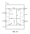
- FIG. 13 is an outside view of a structure where the original (or previous) fenestration product has been removed.
- FIG. 13A shows how neighboring adaptors may interconnect.
- FIG. 14 is a view similar to that shown in FIG. 5 but with the cutout area filled.
- FIG. 15 is a view similar to that shown in FIG. 6 but with the cutout area filled.
- FIG. 16 is a perspective end view showing the cross-sectional shape of a universal adaptor according to some embodiments of this invention.
- FIG. 17 is a view similar to that shown in FIG. 16 but showing cutout areas on one end of the universal adaptor.
- FIG. 18 is a perspective view of a tool used to make cuts on a universal adaptor according to some embodiments of this invention.
- FIG. 19 is a cross-sectional view through a side of a window shown installed to a structure using a universal adaptor according to some embodiments of this invention.
- FIG. 20 is a cross-sectional view through a side of a window shown installed to a structure using a universal adaptor according to other embodiments of this invention.
- FIG. 21 is a cross-sectional view through a side of a window shown installed to a structure using a universal adaptor according to yet other embodiments of this invention.
- FIG. 22 is a front view of a die that may be used to make cutouts on the universal adaptor according to some embodiments of this invention.
- FIG. 23 is a view similar to that shown in FIG. 22 but with the top portion of the die removed.
- FIG. 24 illustrates another adaptor embodiment at the top and an example of its use at the bottom.
- FIG. 25 is a close up view of the bottom portion of FIG. 24 .
- FIG. 26 illustrates another adaptor embodiment at the top and an example of its use at the bottom.
- FIG. 27 is a close up view of the bottom portion of FIG. 26 .
- FIG. 28 illustrates another adaptor embodiment at the top and an example of its use at the bottom.
- FIG. 29 is a close up view of the bottom portion of FIG. 28 .
- FIG. 30 illustrates another adaptor embodiment at the top and an example of its use at the bottom.
- FIG. 31 is a close up view of the bottom portion of FIG. 30 .
- FIG. 32 illustrates another adaptor embodiment.
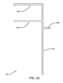
- FIG. 33 is a close up view of the adaptor shown in FIG. 32 .
- FIG. 34 illustrates another adaptor embodiment.
- FIG. 35 is a close up view of the adaptor shown in FIG. 34 .
- FIG. 36 illustrates a portion of another adaptor embodiment.
- FIG. 37 is an end view of a trim piece according to some embodiments of this invention.
- FIG. 12 shows a component 70 that can be modified to make a universal adaptor 72 according to embodiments of this invention.
- the universal adaptor 72 (shown, for example, in FIG. 12 ) can be positioned between a structure (such as structure 10 described above) and a replacement fenestration product (such as replacement window 36 shown in FIG. 9 ). It should be noted, however, that while the universal adaptor 72 of this invention is especially adapted for use with replacement window, it is not limited to that application.
- the component 70 can also be used to install new construction windows, doors, and any other fenestration product chosen with the sound judgment of a person of skill in the art.
- the component 70 and thus universal adaptor 72 , can be made of any material chosen with the sound judgment of a person of skill in the art.
- the universal adaptor 72 may include as many pieces as there are portions of the periphery that define the opening into which a fenestration product is to be attached. In some embodiments the periphery portions are linear sides but that is not a requirement for this invention. The periphery portions may be, in another embodiment, curved surfaces.
- the opening has a rectangular periphery with four portions and thus the adaptor may include four pieces; one that attaches to the top portion of the periphery, another that attaches to one side portion of the periphery, another that attaches to the other side portion of the periphery and another that attaches to the bottom portion of the periphery of the opening.
- the universal adaptor 72 of this invention can be used with openings having peripheries of any size chosen with the sound judgment of a person of skill in the art.
- Non-limiting opening shapes that will work with this invention include any number of sides, thus any polygons, and shapes including curved walls.
- component 70 may have a longitudinal length L1 that can be of any specific length as required.
- the component 70 may be cut along its longitudinal length to make the pieces that define the universal adaptor 72 for any specific application.
- the component 70 and thus the universal adaptor 72 , may have a cross-sectional shape that includes a main wall 74 having a proximal end 76 (toward the inside of the structure once installed) and a distal end 78 (away from the inside of the structure once installed).
- Main wall 74 may be planar, as shown, and may have a height H1. Extending from main wall 74 on one side may be support wall 80 .
- Support wall 80 may be planar, as shown, and may extend at a substantially right angle from main wall 74 .
- Support wall 80 may have a width W4 and may be spaced from the distal end 78 of the main wall 74 a distance D2. Extending from the other side of the main wall 74 may be first receiver wall 82 .
- First receiver wall 82 may be planar, as shown, and may extend at a substantially right angle from main wall 74 .
- First receiver wall 82 may have a width W5 and may extend from the distal end 78 of the main wall 74 , as shown.
- second receiver wall 84 also extending from the other side of the main wall 74 may be second receiver wall 84 .
- Second receiver wall 84 may be planar, as shown, and may extend at a substantially right angle from main wall 74 .
- Second receiver wall 84 may have a width W6 and may be spaced from the distal end 78 of the main wall 74 a distance D3.
- the walls may have a common thickness T1.
- an outer end of first receiver wall 82 may extend proximally and have a curved outer surface 96 , as shown.
- the curved outer surface 96 may form a leading edge used when the universal adaptor 72 is inserted during installation. It should be understood that the curved surface is just one shape that may be used with this invention. Any shape or configuration that would serve as an aid to the installation techniques may be used with this invention.
- H1, W4, D2, W5, W6, D3 and T1 can be any chosen with the sound judgment of a person of skill in the art. It has been determined, however, that the following dimensions are suitable for many applications: H1 is about 2.50 inches; W4 is about 1.25 inches; D2 is about 1.25 inches; W5 and W6 are about 1.50 inches; D3 is about 0.75 inches; and, T1 is about 0.06 inches.
- W5 may in some embodiments equal (though it may not in other embodiments) W6 and support wall 80 may be positioned some distance between the proximal and distal ends 76 , 78 of the main wall 74 .
- first receiver wall 82 and second receiver walls 84 may be about the same size as is typical when forming an exterior panel receiver.
- the space between first and second receiver walls 82 and 84 can serve as an exterior panel receiver 86 , as will be discussed further below.
- FIG. 13 shows a structure 10 where the original (or previous) fenestration product has been removed without removing the exterior siding panels 24 (though the edges near opening 12 may be pulled back slightly).
- the surfaces of the structure defining the opening 12 include cutouts areas (such as cutout areas 52 and 60 shown in FIGS. 5 and 6 )
- the cutout areas may be filled.
- the cutout areas may be filed with filler objects 88 which may be, for one non-limiting example, pieces of wood. In this way the outer surface of objects 88 are coplanar with the outer surface of the jamb 50 and the sill 56 , providing a flat surface onto which a replacement fenestration product can be installed.
- the height H2 and width W7 of opening 12 may be measured (if they are not already known).
- the component 70 may then be cut into a sufficient number of pieces that make up the universal adaptor 72 .
- the component 70 may be cut into four pieces that make up the universal adaptor 72 ; specifically: a first to attach to the bottom of the opening 12 , a second to attach to the top, a third to attach to the left side and a fourth to attach to the right side of the opening 12 .
- each of the four pieces may be cut to a length greater than the height H2 or width W7 of the opening 12 where the piece will be used.
- FIG. 16 shows a bottom piece of a universal adaptor 72 having a total length W7+D4+D4.
- the bottom piece As will become clear below, it is convenient to think of the bottom piece as having a length W7 plus an additional length D4 on each end. While the specific distance D4 may be any chosen with the sound judgment of a person of skill in the art, D4 of about 1.50 inches has been determined to be suitable for many applications.
- the total length of the bottom piece, as well as the top piece may be W7 plus 3.0 inches, in one embodiment.
- each of the left side and right side pieces may be cut out of component 70 to have a length H2+D4+D4, or H2 plus 3.0 inches, in one embodiment.
- a section having a length W7+D4+D4 portions of each end of the bottom piece may be removed. Specifically, at one end, a first cutout section 90 may be made on the proximal end of main wall 74 and a second cutout section 92 may be made between the first and second receiver walls 82 , 84 , as shown. Similar cutout sections are made on the opposite end of the piece (though they are not shown in FIG. 17 ). In one specific embodiment, each of the cutout sections 90 , 92 extend into the piece the distance D4.
- the bottom piece has a mid-section along its length of length W7 to properly cover the bottom of the opening 12 .
- Each end of the bottom piece has cutout sections 90 , 92 that, when attached to the structure 10 , extend outside of the opening 12 , beyond the side edges of the opening 12 .
- the top piece is similarly made, having total length W7+D4+D4 with cutouts 90 , 92 on each end that, when the piece is attached to the structure, extend outside of the opening 12 , beyond the side edges of the opening 12 .
- the left side and right side pieces are similarly made but having a total length H1+D4+D4. They also have cutouts 90 , 92 on each end that, when each piece is attached to the structure, extend outside the opening 12 above and below the opening 12 .
- the cutouts 90 , 92 may be made on site using a die 114 as shown in FIGS. 22-23 or any device capable of properly executed the designed notch dimensions. Specifically, each universal adaptor 72 piece may be placed into the die 114 and the die 114 may then be used in a known manner, such as using a pneumatic cylinder, to create the cutouts 90 , 92 .
- each of the pieces has two ends of distance D4 that extends outside and beyond the opening 12 , they must, and do, engage each other. Specifically, the end of receiver wall 84 on one piece is received within cutout 92 of the neighboring piece. Note that these engagements are established outside and beyond the opening 12 . Specifically, the right side of the top piece engages the top of the right side piece in area A3 shown in FIGS. 13 and 13A (beneath the siding panels 24 ).
- the left side of the top piece engages the top of the left side piece in area A4
- the right side of the bottom piece engages the bottom of the right side piece in area A5
- the left side of the bottom piece engages the bottom of the left side piece in area A6.
- the pieces of the universal adaptor 72 may be modified in one additional way before they are used.
- the support wall 80 may be cut or trimmed to shorten its width from W4 (shown in FIG. 12 ) to width W3 (shown in FIG. 9 ) using a tool, such as tool 18 shown in FIG. 18 .
- each universal adaptor 72 piece may be placed on the tool 112 .
- the tool 112 may then be adjusted (in or out as required) a predetermined distance so that a score line may be added. The distance is predetermined based on the fenestration product being used.
- the distance is predetermined based on the window type; non-limiting examples of window types include: double hung, slider, picture window, patio door and single hung windows.
- window types include: double hung, slider, picture window, patio door and single hung windows.
- the score line is a line where the thickness of the universal adaptor 72 has been reduced. As a result, the installer can easily remove the portion of the support wall 80 around the score line.
- the tool 112 may be used to make other score lines on the component 70 and universal adaptor 72 pieces as needed.
- the universal adaptor 72 can then be used to install a replacement fenestration product such as but not limited to replacement window 36 , shown in FIG. 9 , into an opening, such as opening 12 shown in FIG. 13 .
- the pieces of the adaptor 72 may be installed one at a time though this is not a requirement. It may be easier to begin with the bottom piece, but this is not a requirement and it may be easier to begin with another piece, depending on the particular application.
- FIG. 19 a side piece of the universal adaptor 72 is shown, installed.
- the method of installing it begins with inserting the proximal end 76 of the main wall 74 into the opening 12 with the orientation shown in FIG. 19 .
- the inner surface of the second receiver wall 84 abuts/contacts the mounting flange 20 remaining from the original (or previous) fenestration product that was removed.
- One or more connectors 94 which may be nails, screws or any other suitable connector, are then driven/inserted through the proximal end 76 of the main wall 74 and into the structure 10 to secure the first piece to the structure.
- exterior panel receiver 86 receives the edges/sides of neighboring siding panels 24 .
- the siding panels 24 can be inserted into the neighboring exterior panel receiver 86 either as each piece of the adaptor 72 is installed or after all the pieces have been installed.
- the fenestration product 36 can then be inserted into the opening 12 , from the inside of the structure 10 , with the outside surface 48 (see FIG. 9 ) abutting/contacting the inner surface of support wall 80 and contact surface 46 abutting/contacting periphery 44 (which defines opening 12 ) of structure 10 .
- the fenestration product 36 can then be secured to the structure 10 in a known manner.
- a caulking compound 98 may then be inserted all along the surfaces where the outer end of the support wall 80 contacts the frame 38 of the fenestration product 36 , as shown.
- this invention provides an easy method of installing fenestration products that also provides a high quality seal between components.
- a side piece of the universal adaptor 72 is shown installed in another embodiment.
- a pre-installed exterior panel receiver 100 defined by structure 102 is re-used.
- the pre-installed exterior panel receiver 100 may have been part of the original (and/or previous) fenestration product.
- the preparation of adaptor 72 for installation in this case is the same as described above, except an addition step is required: the second receiver wall 84 (see FIG. 12 ) is cut/trimmed off of the main wall 74 . This cut may also be made on site using the tool 112 shown in FIG. 18 in the same manner, using score lines, as described above.
- the installation of the adaptor 72 pieces is also as explained above except: (1) as the adaptor pieces 72 are inserted, the inner surface of the first receiver wall 82 abuts/contacts the outer surface of the pre-installed structure 102 ; and, (2) the siding panels 24 can be inserted into the neighboring exterior panel receiver 100 (not exterior panel receiver 86 ).
- FIG. 21 a side piece of the universal adaptor 72 is shown installed in another embodiment.
- the adaptor 72 of this invention is especially adapted for use when installing a replacement fenestration product. It can also be used, however, when installing a new fenestration product, such as window 108 , having a frame 110 , as shown in FIG. 21 , into a newly constructed structure 10 .
- the new fenestration product is similar to the previously described replacement fenestration product 36 , shown in FIG. 9 . Because the window 108 in this embodiment is installed into a new construction structure 10 , there is no reason to create cutout areas 52 , 58 (shown in FIGS. 5 and 6 ).
- the installation of the fenestration product 108 is similar to the installation of fenestration product 36 described above with reference to FIG. 19 except that as the adaptor pieces 72 are installed, the inner surfaces of the second receiver walls 84 abut/contact the surfaces 22 of the structure 10 (see also FIG. 1 ).
- FIGS. 24 and 25 show another universal adaptor 72 a used to support a fenestration product 36 a to a structure.
- the adaptor 72 a may have a main wall 74 a , a support wall 80 a and a receiver wall 82 a . Note that for this embodiment the main wall 74 a is angled with respect to the support wall 80 a and receiver wall 82 a .
- the support wall 80 a extends from one end and one side of the main wall 74 a while the receiver wall 82 a extends from the opposite end and opposite side of the main wall 74 a .
- the adaptor 72 a may be secured to the structure, in this embodiment a window sill, with connector 94 a and a sill extender support (sometimes referred to as a bridge support) 66 a as is well known in the art.
- a caulking compound or other sealant 98 a may be used to seal a connection between the adaptor 72 a and the structure.
- FIGS. 26 and 27 show another universal adaptor 72 b used to support a fenestration product 36 b to a structure.
- the adaptor 72 b may have a main wall 74 b , a support wall 80 b and a receiver wall 82 b .
- the support wall 80 b extends from one side of the main wall 74 b at a mid-section of the main wall 74 b while the receiver wall 82 b extends from the opposite side of the main wall 74 b at an end of the main wall 74 b .
- the end of the support wall 82 b has curved outer surface 96 b .
- the adaptor 72 b may be secured to the structure with connector 94 b and a caulking compound or other sealant 98 b may be used to seal a connection between the adaptor 72 b and the structure.
- FIGS. 28 and 29 show another universal adaptor 72 c used to support a fenestration product 36 c to a structure.
- the adaptor 72 c may have a main wall 74 c , a support wall 80 c and a receiver wall 82 c .
- the support wall 80 c extends from one side of the main wall 74 c at one end of the main wall 74 c while the receiver wall 82 c extends from the opposite side of the main wall 74 b at an opposite end of the main wall 74 c .
- the main wall 74 c has two parts, 75 and 77 that are angled with respect to each other and thus on different planes. This design is suitable for this application.
- the adaptor 72 c may be secured to the structure, in this embodiment a window sill, with connector 94 c and a sill extender support (or bridge support) 66 c as is well known in the art.
- a caulking compound or other sealant 98 c may be used to seal a connection between the adaptor 72 c and the structure.
- FIGS. 30 and 31 show another universal adaptor 72 d used to support a fenestration product 36 d to a structure.
- the adaptor 72 d may have a main wall 74 d , a support wall 80 d and a receiver wall 82 d .
- the support wall 80 d extends from one side of the main wall 74 d at one end of the main wall 74 d while the receiver wall 82 d extends from the same side of the main wall 74 d at an opposite end of the main wall 74 d .
- the receiver wall 82 d has two parts, 79 and 81 that are angled with respect to each other (at a right angle or 90 degrees in the embodiment shown) and thus are on different planes.
- the main wall 74 d also has second and third receiver walls 84 d and 83 that extend therefrom.
- This design is suitable for this application, as shown.
- the adaptor 72 d may be secured to the structure with connector 94 d and a caulking compound or other sealant 98 d may be used to seal a connection between the adaptor 72 d and the structure.
- a trim component 68 that comes with the fenestration product 365 may optionally be used.
- FIGS. 32 and 33 show another universal adaptor 72 e used to support a fenestration product 36 e to a structure.
- This structure includes an outer wall portion with layers labeled “vinyl siding,” “rigid foam” (with half inch thickness indicated), “original siding” (with half inch thickness indicated), “OSB” (which means Oriented Strand Board and with half inch thickness indicated), and “gypsum” (with half inch thickness indicated).
- This structure also includes an inner wall portion with a layer of “drywall” (with half inch thickness indicated).
- the adaptor 72 e may have a main wall 74 e , a support wall 80 e and first and second receiver walls 82 e and 84 e . Note that adaptor 72 e is similar to adaptor 72 described above (see, for example, FIG. 13 ) but with wall lengths and relative positions varied to meet the specific requirement.
- FIGS. 34 and 35 show another universal adaptor 72 f used to support a fenestration product 36 f to a structure.
- This structure includes an outer wall portion with layers labeled “brick,” “air space”, and “gypsum” (with half inch thickness indicated).
- This structure also includes an inner wall portion with a layer of “drywall” (with half inch thickness indicated).
- the adaptor 72 f may have a main wall 74 f , a support wall 80 f and first and second receiver walls 82 f and 84 f . Note that adaptor 72 f is just like adaptor 72 e described above (see, for example, FIG.
- One way to acquire adaptor 72 f is to take adaptor 72 e and cut or trim walls 82 e and 84 e to the widths of walls 82 f and 84 f.
- FIG. 36 shows a portion of another universal adaptor 72 g which may be used to support a fenestration product (not shown) to a structure (not shown).
- the adaptor 72 g may have a main wall 74 g and first and second receiver walls 82 g and 84 g .
- the distal end or tip of first receiver wall 82 g may have a curved outer surface 96 g similar to curved surface 96 described above.
- the distal end or tip of second receiver wall 82 g may have a beveled edge 85 .
- the beveled edge 85 is useful in some embodiments to make it easier to insert the adaptor to a fenestration product and/or structure.
- a trim piece 120 may be used with an adaptor. Such a trim piece 120 may be used to improve the ornamental look of the fenestration product and/or the structure—similar to a window frame.
- the trim piece 120 may, for example, have a color and or design that matches at least one of the structure and the fenestration product.
- the trim piece 120 in one embodiment may comprise a pair of fingers 122 , 124 that can be separated to receive a portion of the adaptor.
- the trim piece may “clip” or “snap” onto any of the adaptor walls with a pressure fit between the fingers 122 , 124 and the adaptor.
- trim piece 120 can be any chosen with the sound judgment of a person of skill in the art, for the embodiment shown, finger 122 is wider than finger 124 and the tip of finger 124 is angled away from finger 122 (see reference 126 ) to make it easy to attach the trim piece 120 to the adaptor.
- the trim piece 120 may have any longitudinal length (into the page as shown in FIG. 37 ) as required. The longitudinal length of the trim piece 12 may be cut as required for any application. Once the trim piece (or pieces) 120 is (are) cut, it (they) can be attached to the adaptor (adaptors).
Landscapes
- Engineering & Computer Science (AREA)
- Civil Engineering (AREA)
- Structural Engineering (AREA)
- Load-Bearing And Curtain Walls (AREA)
- Building Environments (AREA)
Abstract
Description
Claims (10)
Priority Applications (1)
| Application Number | Priority Date | Filing Date | Title |
|---|---|---|---|
| US14/293,161 US9458659B2 (en) | 2013-06-24 | 2014-06-02 | Universal adaptor and methods for installing fenestration products |
Applications Claiming Priority (2)
| Application Number | Priority Date | Filing Date | Title |
|---|---|---|---|
| US201361838471P | 2013-06-24 | 2013-06-24 | |
| US14/293,161 US9458659B2 (en) | 2013-06-24 | 2014-06-02 | Universal adaptor and methods for installing fenestration products |
Publications (2)
| Publication Number | Publication Date |
|---|---|
| US20140373482A1 US20140373482A1 (en) | 2014-12-25 |
| US9458659B2 true US9458659B2 (en) | 2016-10-04 |
Family
ID=52109795
Family Applications (1)
| Application Number | Title | Priority Date | Filing Date |
|---|---|---|---|
| US14/293,161 Expired - Fee Related US9458659B2 (en) | 2013-06-24 | 2014-06-02 | Universal adaptor and methods for installing fenestration products |
Country Status (1)
| Country | Link |
|---|---|
| US (1) | US9458659B2 (en) |
Families Citing this family (2)
| Publication number | Priority date | Publication date | Assignee | Title |
|---|---|---|---|---|
| EP3095944B1 (en) * | 2015-05-18 | 2021-01-13 | ISO-Chemie GmbH | Structure section having a window frame |
| FR3100557B1 (en) * | 2019-09-09 | 2021-09-17 | Samibois Samiplast | SLEEPING PROFILE FOR SIDING RECEPTION |
Citations (19)
| Publication number | Priority date | Publication date | Assignee | Title |
|---|---|---|---|---|
| US1568865A (en) * | 1922-11-25 | 1926-01-05 | Sidney U Barr | Casement window |
| US4513549A (en) * | 1983-03-25 | 1985-04-30 | United States Gypsum Company | Pre-mitered doorframe assembly for partition wall construction |
| US5392574A (en) * | 1987-08-10 | 1995-02-28 | Sealmaster, Inc. | Window frame for manufactured housing |
| US5577355A (en) | 1995-03-14 | 1996-11-26 | Pillar Plastics Limited | Two piece window frame generating from a single extrusion |
| US5651222A (en) * | 1994-07-01 | 1997-07-29 | East Coast Millwork Distributors, Inc. | PVC window cladding with corner expansion joints |
| US5706620A (en) | 1992-05-29 | 1998-01-13 | Royal Building Systems (Cdn) Limited | Thermoplastic structural system and components therefor and method of making same |
| US5713159A (en) | 1994-12-14 | 1998-02-03 | Dominion Plastics Inc. | Multi part plastic lineal |
| US6526709B1 (en) * | 2002-01-09 | 2003-03-04 | Rodney Allen Jacobsen | Replacement window installation and flashing system |
| US6631595B1 (en) * | 2001-07-23 | 2003-10-14 | Pella Corp | Brickmold |
| US20030221381A1 (en) * | 2002-05-29 | 2003-12-04 | Ting Raymond M.L. | Exterior vision panel system |
| US20050050815A1 (en) * | 2002-06-07 | 2005-03-10 | David Engebretson | Fenestration frame assemblies and associated methods |
| US20050072073A1 (en) * | 2003-10-02 | 2005-04-07 | Inelli John D. | Window sleeve for mounting framed windows |
| US20060143996A1 (en) * | 2004-12-30 | 2006-07-06 | Jorge Alvarado | Universal fenestration cap system and method |
| US20060272238A1 (en) * | 2005-04-27 | 2006-12-07 | Nichiha Co., Ltd. | Opening portion periphery decorative member, opening portion periphery construction structure, and opening portion periphery construction method |
| US20080134595A1 (en) * | 2006-12-12 | 2008-06-12 | Pacc Systems I.P., Llc | Reinforced masonry sill and threshold sealant backer |
| US20090044466A1 (en) * | 2007-08-13 | 2009-02-19 | Andres Craig E | Window and Door Frame Assembly Apparatus and Method |
| US8402707B2 (en) | 2010-01-29 | 2013-03-26 | Royal Group Inc. | Interlocking panel system |
| US8490350B1 (en) * | 2009-12-09 | 2013-07-23 | Troy Anthony Greely | Exterior window and door trim |
| US20140174007A1 (en) * | 2012-12-21 | 2014-06-26 | Milgard Manufacturing Incorporated | Window trim system |
-
2014
- 2014-06-02 US US14/293,161 patent/US9458659B2/en not_active Expired - Fee Related
Patent Citations (20)
| Publication number | Priority date | Publication date | Assignee | Title |
|---|---|---|---|---|
| US1568865A (en) * | 1922-11-25 | 1926-01-05 | Sidney U Barr | Casement window |
| US4513549A (en) * | 1983-03-25 | 1985-04-30 | United States Gypsum Company | Pre-mitered doorframe assembly for partition wall construction |
| US5392574A (en) * | 1987-08-10 | 1995-02-28 | Sealmaster, Inc. | Window frame for manufactured housing |
| US5706620A (en) | 1992-05-29 | 1998-01-13 | Royal Building Systems (Cdn) Limited | Thermoplastic structural system and components therefor and method of making same |
| US5651222A (en) * | 1994-07-01 | 1997-07-29 | East Coast Millwork Distributors, Inc. | PVC window cladding with corner expansion joints |
| US5713159A (en) | 1994-12-14 | 1998-02-03 | Dominion Plastics Inc. | Multi part plastic lineal |
| US5577355A (en) | 1995-03-14 | 1996-11-26 | Pillar Plastics Limited | Two piece window frame generating from a single extrusion |
| US6631595B1 (en) * | 2001-07-23 | 2003-10-14 | Pella Corp | Brickmold |
| US6526709B1 (en) * | 2002-01-09 | 2003-03-04 | Rodney Allen Jacobsen | Replacement window installation and flashing system |
| US20030221381A1 (en) * | 2002-05-29 | 2003-12-04 | Ting Raymond M.L. | Exterior vision panel system |
| US20050050815A1 (en) * | 2002-06-07 | 2005-03-10 | David Engebretson | Fenestration frame assemblies and associated methods |
| US20050072073A1 (en) * | 2003-10-02 | 2005-04-07 | Inelli John D. | Window sleeve for mounting framed windows |
| US20060143996A1 (en) * | 2004-12-30 | 2006-07-06 | Jorge Alvarado | Universal fenestration cap system and method |
| US20060272238A1 (en) * | 2005-04-27 | 2006-12-07 | Nichiha Co., Ltd. | Opening portion periphery decorative member, opening portion periphery construction structure, and opening portion periphery construction method |
| US20080134595A1 (en) * | 2006-12-12 | 2008-06-12 | Pacc Systems I.P., Llc | Reinforced masonry sill and threshold sealant backer |
| US20090044466A1 (en) * | 2007-08-13 | 2009-02-19 | Andres Craig E | Window and Door Frame Assembly Apparatus and Method |
| US8490350B1 (en) * | 2009-12-09 | 2013-07-23 | Troy Anthony Greely | Exterior window and door trim |
| US8402707B2 (en) | 2010-01-29 | 2013-03-26 | Royal Group Inc. | Interlocking panel system |
| US8596000B2 (en) | 2010-01-29 | 2013-12-03 | Royal Group, Inc. | Interlocking panel system |
| US20140174007A1 (en) * | 2012-12-21 | 2014-06-26 | Milgard Manufacturing Incorporated | Window trim system |
Also Published As
| Publication number | Publication date |
|---|---|
| US20140373482A1 (en) | 2014-12-25 |
Similar Documents
| Publication | Publication Date | Title |
|---|---|---|
| US10683660B2 (en) | Exterior wall system | |
| US8490350B1 (en) | Exterior window and door trim | |
| US9194173B2 (en) | System and method for installing trim with a hidden fastener system | |
| US20050262782A1 (en) | Self flashing assembly | |
| US7165364B2 (en) | Window sleeve for mounting framed windows | |
| US7921620B2 (en) | Method of framing a wall penetration | |
| JP5946869B2 (en) | Outer wall mounting member and outer wall structure | |
| US20190112863A1 (en) | Window jamb extender for new or replacement window | |
| US9458659B2 (en) | Universal adaptor and methods for installing fenestration products | |
| US5351452A (en) | Drywalling method and apparatus | |
| US20120222383A1 (en) | Brick mould trim | |
| US20120227338A1 (en) | Milcore jamb strip | |
| US20070277455A1 (en) | Vinyl window with flush trim | |
| US20220025695A1 (en) | Sill pan assembly for door systems and method of installation | |
| US8984820B1 (en) | Geometrics window system | |
| GB2576349A (en) | Improvements in or relating to sash members | |
| US9290987B2 (en) | Window frame with jamb extender | |
| US20050188625A1 (en) | Archway and archway construction | |
| US10227815B2 (en) | Window jamb extender for new or replacement window | |
| US10125532B2 (en) | Replacement window jamb extender | |
| JP2010126910A (en) | Sash | |
| WO2008115509A1 (en) | Modular molding system and methods thereof | |
| AU2020103981B4 (en) | Fixing system for architectural mouldings | |
| EP2775067B1 (en) | Jamb facing profile | |
| US20040003552A1 (en) | Window and door sealing system and process |
Legal Events
| Date | Code | Title | Description |
|---|---|---|---|
| AS | Assignment |
Owner name: PROFILE: UNIVERSAL WINDOW ADAPTER, LLC, OHIO Free format text: ASSIGNMENT OF ASSIGNORS INTEREST;ASSIGNOR:THORNDYKE, CARRIE A;REEL/FRAME:038087/0368 Effective date: 20160310 Owner name: PROFILE: UNIVERSAL WINDOW ADAPTER, LLC, OHIO Free format text: ASSIGNMENT OF ASSIGNORS INTEREST;ASSIGNOR:NEELY, JON A;REEL/FRAME:038087/0371 Effective date: 20160310 |
|
| STCF | Information on status: patent grant |
Free format text: PATENTED CASE |
|
| FEPP | Fee payment procedure |
Free format text: MAINTENANCE FEE REMINDER MAILED (ORIGINAL EVENT CODE: REM.); ENTITY STATUS OF PATENT OWNER: SMALL ENTITY |
|
| LAPS | Lapse for failure to pay maintenance fees |
Free format text: PATENT EXPIRED FOR FAILURE TO PAY MAINTENANCE FEES (ORIGINAL EVENT CODE: EXP.); ENTITY STATUS OF PATENT OWNER: SMALL ENTITY |
|
| STCH | Information on status: patent discontinuation |
Free format text: PATENT EXPIRED DUE TO NONPAYMENT OF MAINTENANCE FEES UNDER 37 CFR 1.362 |
|
| FP | Expired due to failure to pay maintenance fee |
Effective date: 20201004 |