US9457348B2 - Device for sampling and transporting nano-objects contained in aerosols for the analysis thereof - Google Patents
Device for sampling and transporting nano-objects contained in aerosols for the analysis thereof Download PDFInfo
- Publication number
- US9457348B2 US9457348B2 US14/349,249 US201214349249A US9457348B2 US 9457348 B2 US9457348 B2 US 9457348B2 US 201214349249 A US201214349249 A US 201214349249A US 9457348 B2 US9457348 B2 US 9457348B2
- Authority
- US
- United States
- Prior art keywords
- parts
- filter
- clipping means
- clipping
- cassette
- Prior art date
- Legal status (The legal status is an assumption and is not a legal conclusion. Google has not performed a legal analysis and makes no representation as to the accuracy of the status listed.)
- Active, expires
Links
- 238000005070 sampling Methods 0.000 title claims abstract description 42
- 238000004458 analytical method Methods 0.000 title claims abstract description 19
- 239000000443 aerosol Substances 0.000 title claims description 20
- 238000000034 method Methods 0.000 claims description 17
- 230000000295 complement effect Effects 0.000 claims description 11
- -1 polyethylene terephthalate Polymers 0.000 claims description 11
- 229920012196 Polyoxymethylene Copolymer Polymers 0.000 claims description 6
- 239000004743 Polypropylene Substances 0.000 claims description 6
- 229920003229 poly(methyl methacrylate) Polymers 0.000 claims description 6
- 229920001707 polybutylene terephthalate Polymers 0.000 claims description 6
- 229920000139 polyethylene terephthalate Polymers 0.000 claims description 6
- 239000005020 polyethylene terephthalate Substances 0.000 claims description 6
- 239000004926 polymethyl methacrylate Substances 0.000 claims description 6
- 229920001155 polypropylene Polymers 0.000 claims description 6
- 238000003825 pressing Methods 0.000 claims description 6
- 239000012815 thermoplastic material Substances 0.000 claims description 5
- 238000005530 etching Methods 0.000 claims description 4
- 229920002292 Nylon 6 Polymers 0.000 claims description 3
- 229920002302 Nylon 6,6 Polymers 0.000 claims description 3
- 239000004417 polycarbonate Substances 0.000 claims description 3
- 229920000515 polycarbonate Polymers 0.000 claims description 3
- 238000000605 extraction Methods 0.000 abstract description 2
- 230000007246 mechanism Effects 0.000 abstract 2
- 239000002245 particle Substances 0.000 description 11
- 239000000463 material Substances 0.000 description 10
- 239000002086 nanomaterial Substances 0.000 description 6
- 238000011109 contamination Methods 0.000 description 4
- 230000004907 flux Effects 0.000 description 4
- VYPSYNLAJGMNEJ-UHFFFAOYSA-N Silicium dioxide Chemical compound O=[Si]=O VYPSYNLAJGMNEJ-UHFFFAOYSA-N 0.000 description 3
- 238000007646 gravure printing Methods 0.000 description 3
- 239000002105 nanoparticle Substances 0.000 description 3
- 230000008569 process Effects 0.000 description 3
- 230000029058 respiratory gaseous exchange Effects 0.000 description 3
- PXHVJJICTQNCMI-UHFFFAOYSA-N Nickel Chemical compound [Ni] PXHVJJICTQNCMI-UHFFFAOYSA-N 0.000 description 2
- 239000002033 PVDF binder Substances 0.000 description 2
- 239000000654 additive Substances 0.000 description 2
- 150000001875 compounds Chemical class 0.000 description 2
- 230000008021 deposition Effects 0.000 description 2
- 239000007789 gas Substances 0.000 description 2
- 230000036541 health Effects 0.000 description 2
- 229920000609 methyl cellulose Polymers 0.000 description 2
- 239000001923 methylcellulose Substances 0.000 description 2
- 229920001343 polytetrafluoroethylene Polymers 0.000 description 2
- 239000004810 polytetrafluoroethylene Substances 0.000 description 2
- 229920002981 polyvinylidene fluoride Polymers 0.000 description 2
- 238000007789 sealing Methods 0.000 description 2
- OKTJSMMVPCPJKN-UHFFFAOYSA-N Carbon Chemical compound [C] OKTJSMMVPCPJKN-UHFFFAOYSA-N 0.000 description 1
- 239000004793 Polystyrene Substances 0.000 description 1
- RTAQQCXQSZGOHL-UHFFFAOYSA-N Titanium Chemical compound [Ti] RTAQQCXQSZGOHL-UHFFFAOYSA-N 0.000 description 1
- 239000000853 adhesive Substances 0.000 description 1
- 230000001070 adhesive effect Effects 0.000 description 1
- PNEYBMLMFCGWSK-UHFFFAOYSA-N aluminium oxide Inorganic materials [O-2].[O-2].[O-2].[Al+3].[Al+3] PNEYBMLMFCGWSK-UHFFFAOYSA-N 0.000 description 1
- 239000010425 asbestos Substances 0.000 description 1
- 229910052799 carbon Inorganic materials 0.000 description 1
- 239000006229 carbon black Substances 0.000 description 1
- 239000001913 cellulose Substances 0.000 description 1
- 229920002678 cellulose Polymers 0.000 description 1
- 239000011248 coating agent Substances 0.000 description 1
- 238000000576 coating method Methods 0.000 description 1
- 239000002537 cosmetic Substances 0.000 description 1
- 239000000428 dust Substances 0.000 description 1
- 238000005516 engineering process Methods 0.000 description 1
- 230000007613 environmental effect Effects 0.000 description 1
- 239000003344 environmental pollutant Substances 0.000 description 1
- 239000000945 filler Substances 0.000 description 1
- 238000001914 filtration Methods 0.000 description 1
- 239000003365 glass fiber Substances 0.000 description 1
- 239000003292 glue Substances 0.000 description 1
- 238000000892 gravimetry Methods 0.000 description 1
- 238000011065 in-situ storage Methods 0.000 description 1
- 238000002347 injection Methods 0.000 description 1
- 239000007924 injection Substances 0.000 description 1
- 239000012948 isocyanate Substances 0.000 description 1
- 150000002513 isocyanates Chemical class 0.000 description 1
- 238000010330 laser marking Methods 0.000 description 1
- 238000003754 machining Methods 0.000 description 1
- 238000005259 measurement Methods 0.000 description 1
- 239000012528 membrane Substances 0.000 description 1
- 238000004377 microelectronic Methods 0.000 description 1
- 238000000386 microscopy Methods 0.000 description 1
- 238000000465 moulding Methods 0.000 description 1
- 229910052759 nickel Inorganic materials 0.000 description 1
- 239000003973 paint Substances 0.000 description 1
- 239000004033 plastic Substances 0.000 description 1
- 229920003023 plastic Polymers 0.000 description 1
- 231100000719 pollutant Toxicity 0.000 description 1
- 239000011148 porous material Substances 0.000 description 1
- 230000002265 prevention Effects 0.000 description 1
- 238000007639 printing Methods 0.000 description 1
- 238000003672 processing method Methods 0.000 description 1
- 230000005180 public health Effects 0.000 description 1
- 239000010453 quartz Substances 0.000 description 1
- 238000004064 recycling Methods 0.000 description 1
- 229910052895 riebeckite Inorganic materials 0.000 description 1
- 239000000377 silicon dioxide Substances 0.000 description 1
- 239000007787 solid Substances 0.000 description 1
- 239000000126 substance Substances 0.000 description 1
- 239000010936 titanium Substances 0.000 description 1
- 229910052719 titanium Inorganic materials 0.000 description 1
- 238000011144 upstream manufacturing Methods 0.000 description 1
- 238000005406 washing Methods 0.000 description 1
- 238000004846 x-ray emission Methods 0.000 description 1
Images


Classifications
-
- B—PERFORMING OPERATIONS; TRANSPORTING
- B01—PHYSICAL OR CHEMICAL PROCESSES OR APPARATUS IN GENERAL
- B01L—CHEMICAL OR PHYSICAL LABORATORY APPARATUS FOR GENERAL USE
- B01L3/00—Containers or dishes for laboratory use, e.g. laboratory glassware; Droppers
- B01L3/50—Containers for the purpose of retaining a material to be analysed, e.g. test tubes
- B01L3/502—Containers for the purpose of retaining a material to be analysed, e.g. test tubes with fluid transport, e.g. in multi-compartment structures
- B01L3/5023—Containers for the purpose of retaining a material to be analysed, e.g. test tubes with fluid transport, e.g. in multi-compartment structures with a sample being transported to, and subsequently stored in an absorbent for analysis
-
- G—PHYSICS
- G01—MEASURING; TESTING
- G01N—INVESTIGATING OR ANALYSING MATERIALS BY DETERMINING THEIR CHEMICAL OR PHYSICAL PROPERTIES
- G01N1/00—Sampling; Preparing specimens for investigation
- G01N1/02—Devices for withdrawing samples
- G01N1/22—Devices for withdrawing samples in the gaseous state
- G01N1/2202—Devices for withdrawing samples in the gaseous state involving separation of sample components during sampling
- G01N1/2205—Devices for withdrawing samples in the gaseous state involving separation of sample components during sampling with filters
-
- G—PHYSICS
- G01—MEASURING; TESTING
- G01N—INVESTIGATING OR ANALYSING MATERIALS BY DETERMINING THEIR CHEMICAL OR PHYSICAL PROPERTIES
- G01N1/00—Sampling; Preparing specimens for investigation
- G01N1/02—Devices for withdrawing samples
- G01N1/22—Devices for withdrawing samples in the gaseous state
- G01N1/2273—Atmospheric sampling
- G01N2001/2276—Personal monitors
-
- G—PHYSICS
- G01—MEASURING; TESTING
- G01N—INVESTIGATING OR ANALYSING MATERIALS BY DETERMINING THEIR CHEMICAL OR PHYSICAL PROPERTIES
- G01N1/00—Sampling; Preparing specimens for investigation
- G01N1/02—Devices for withdrawing samples
- G01N1/22—Devices for withdrawing samples in the gaseous state
- G01N2001/2285—Details of probe structures
- G01N2001/2288—Filter arrangements
Definitions
- the invention relates to a device for sampling and transporting nano-objects contained in aerosols for the analysis thereof.
- the invention is applicable to sampling and transporting nanoparticles or nano-objects contained in aerosols.
- nano-objects objects at least one unit size of which is lower than about 100 nm.
- nanoparticle particles generally (but not only) spherical which unit average diameter is lower than about 100 nm, in accordance with ISO TS/27687 standard.
- the invention is also applicable to sampling and transporting micrometric size particles contained in aerosols.
- nanometric size particles have been intensively researched and their use has started to spread in various fields such as health, microelectronics, energy technologies or consumer products such as paints and cosmetics.
- sampling or sampling processing method choice consists in sucking an air flux likely to be particle-loaded through a filter which is ex post analysed by various techniques (gravimetry, microscopy, XRF, . . . )
- sampling devices also called cassette samplers
- cassette samplers which are portable and which have to sample an aerosol contamination likely to be inhaled by the mouth or nose of an individual when he breathes.
- U.S. Pat. No. 4,961,916 relates to a device for sampling gases and particulate pollutants comprising a cassette inside which three filters are stacked upon each other and comprising two ports on either side of these filters, the first one opening into the outside environment likely to be polluted and the other on a pipe connected to a suction pump.
- the first filter enables to collect only the particulate fraction of the aerosol
- the second, impregnated beforehand with a reactive enables to selectively react with one or more gaseous compounds
- the third filter has only the function of rigidifying the filtering assembly.
- the sampling aimed at in this patent is collecting gaseous and particulate isocyanates which are in polluted air.
- U.S. Pat. No. 5,205,155 in turn discloses a device for sampling asbestos fibres likely to be suspended in air and concerns the non-uniform deposition on the filter accommodated in the sampling cassette.
- the patent proposes, to overcome this, to shape the cassette inlet, that is the one in proximity of the suction port of the environment concerned, as a flared shape and to make it smooth in order to promote a homogeneous particle deposition onto the filter.
- US Patent Application 2008/0196514 A1 relates to a device for individually sampling dust which is used to collect the inhalable fraction of airborne particles.
- This patent describes different aspect ratios of the cassette (length L/to inlet diameter D of the aperture ratios), which, according to it, enable suction sampling to be improved. Furthermore, this patent mentions that to have the best representativity of inspiration through nose, it is advantageous to provide a vertical orientation of the air flux sucked from bottom to top.
- the general purpose of the invention is thus to provide a device for sampling and transporting nano-objects likely to be present in an aerosol for the elementary analysis thereof which does not have the aforementioned drawbacks, and which thus enables to ensure the sampling integrity and definitely providing the traceability thereof up to the actual analysis.
- the elementary analysis is an analysis allowing to determine what atomic elements (Titanium, Carbone, Nickel, etc.) are present as well as their atomic percentage in the sample. On the other hand, an elementary analysis does not enable the structure or assembly of these elements together to be determined.
- a particular purpose of the invention is to provide a device of this type which is simply made and inexpensive.
- the object of the invention is a device for sampling and transporting nano-objects likely to be present in an aerosol for the analysis thereof, comprising a porous sampling filter capable of trapping nano-objects likely to be suspended in the aerosol, a cassette consisting of a first part and a second part which are provided with mutual assembly means and filter holding means, the first and second parts defining, in their assembled position, a cavity wherein the filter is accommodated by being held, and at least one seal capable of sealing between the cavity and outside.
- the mutual assembly means comprise:
- one of the parts is provided with holes opening each at a time onto outside of the parts and on one of the cooperation zones of the clipping means, the holes being each capable of accommodating a pin for unclipping both parts by applying a thrust force on the pins against the first or second clipping means.
- the clipping means can be physically reached only through pins individually accommodated in the holes but not manually or by using a tool from the space outside to the device in its assembled position.
- the cassette is secured which cannot be unintentionally opened, the opening thereof for the actual analysis of the sample requiring a tool suitable for separating both portions of the cassette.
- This cassette is comprised of two parts between which is located a filter holder acting to support the filter by keeping it tensioned and planar and participating in the sealing between the upper and lower portions of the cassette. Finally, the cassette has in its median portion an opening enabling the identifier of the filter holder to be read.
- the three components of the cassette are characterised in that they are made of plastic material.
- the first clipping means consist of a number equal to n of elastically deformable tabs which end is shaped as a hook and which are arranged on the first part by being relatively distant from each other at an angular position equal to 2 ⁇ divided by the number n, that is 2 ⁇ /n
- the second clipping means consist of a same number n of recesses or lugs shaped by being complementary to the hooks and arranged on the second part by being relatively distant from each other at the same angular position at 2 ⁇ /n as the tabs.
- the number n is between 2 and 20, further preferably between 2 and 4.
- the filter holder means advantageously comprise two shoulders, one made on an inner periphery of the first part and the other on an inner periphery of the second part, and the device comprises a filter holder pinchedly held between both shoulders.
- the filter holder is preferably compressively deformable in order to be crushed by the first and second parts in the assembled position and thus to make up a single seal.
- the device preferably comprises at least one elastomeric seal pressing against at least one of the shoulders.
- the first and second parts and the filter holder are advantageously based on thermoplastic material, preferably of polyethylene terephthalate (PET), polybutylene terephthalate (PBT), polymethylmethacrylate (PMMA), polyamide 6 (PA6), polyamide 66 (PA66), polycarbonate (PC), polypropylene (PP) or polyoxymethylene copolymer (POM-C).
- the material(s) forming the parts and/or the filter holder can contain a carbon black filler having an antielectrostatic function.
- the mutual assembly means can further comprise an annular edge on each of the first and second parts in order to perform, in addition to clipping, mutual surface pressing between the parts in their assembled position.
- At least one of the parts comprises a notch opening on either side of the annular edge and in that the filter holder comprises a tongue complementary to the notch(es) and on which a filter identifying element is attached, such that in the assembled position of the parts, the identifying element is in contact with the outside environment.
- the identifying element is preferably an electronic chip or a radiofrequency identification (RFID) tag or a two dimensional bar code, of the Datamatrix® type. It can be attached by a bonding technique, through etching, overinjection or indirect gravure printing.
- RFID radiofrequency identification
- the invention also relates to a tool for performing unclipping of both parts of the device previously defined, comprising pins arranged relatively distant from each other at the same position as the holes.
- the tool can further comprise mechanical guide means capable of guiding the tool relatively to the part provided with holes to facilitate the simultaneous pushing of the pins against the first or second clipping means.
- the invention finally relates to the use of the device previously defined, as a device for tracking exposure of operators in a station for making nano-objects or developing nanomaterials.
- FIG. 1 is a profile view of the cassette for sampling a device according to the invention, the cassette being in a closed configuration,
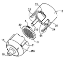
- FIG. 2 is an exploded perspective view of the device according to FIG. 1 showing both parts of the cassette in non-assembled position and the filter with its filter holder,
- FIG. 3 is a view identical to FIG. 2 further showing a tool in accordance with the invention allowing the secured opening of the cassette
- FIGS. 4 and 5 are exploded perspective views showing alternative embodiments of the device according to the invention.
- the device according to the invention first comprises a filter 30 suitable for trapping nano-objects likely to be suspended in air, which is accommodated and held in a cavity formed by a cassette C in a closed configuration.
- the sampling method according to the invention consists in orienting the closed cassette such that the air to be analysed is sucked by a pump not represented from a port 20 and comes out through the port 10 to go then to the pump.
- the suction can of course be provided according to a reverse path, that is from the port 10 to the port 20 .
- the nano-objects or micrometric size particles thus sucked will be collected on the filter 30 held in the cassette.
- the cassette is oriented such that it is vertical with the suction port 20 downwards and that there is a suction from bottom to top.
- the cassette is oriented to have the suction port 20 horizontally.
- the device according to the invention enables the sample sampling and the transport of trapped nano-objects, in a secured way and with a perfect traceability.
- the cassette consists of two parts 1 , 2 of generally cylindrical shape.
- the upper part 2 is provided with flexible tabs 21 or in other words elastically deformable, which end is shaped as a hook 210 .
- the lower part 1 is provided with recesses 11 individually complementary to a tab 21 with an end also recessed or as a bump complementary individually with a hook 210 . It can of course be provided within the scope of the present invention with an arrangement of hooks or reversed complementary bump, that is with hooks individually in a recess of the part 1 and with tabs with a bump on the part 2 .
- the relative angular arrangement between the flexible tabs 21 of the upper part 2 is identical to that of the recesses 11 of the lower part 1 .
- the tabs 21 With their hooks 210 come to smugly fit and accurately clip in the recesses 11 and recesses or bumps 110 ( FIG. 1 ).
- no tab 21 projects from the parts 1 , 2 : in other words, no clipping means 11 , 110 , 21 , 210 is accessible from outside and only the use of an adequate tool 5 as described hereinafter enables both parts to be disunited.
- any unintentional opening of the cassette outside of the analysis laboratory intended to accurately analyse the particles trapped by the filter 3 is prevented.
- the contamination risks thereof are restricted, which are not really representative of the sampling which could occur either by an increase in the amount of particles trapped by the filter, or by a decrease in the amount of particles trapped on the filter (peeling off) or by addition of particles having a nature different to those sampled.
- the lower part 21 is provided with holes 13 opening both to outside and on the zone where the bumps or recesses 110 are arranged, that is at the zone where the tabs 21 with theirs hooks 210 cooperating by clipping on the corresponding bumps or recesses 210 . Therefore, there are as many holes 13 as complementary clipping means.
- all the pins 50 are attached on a tool 5 represented in FIG. 3 which also comprises rigid tabs 51 distant from each other so that they can accommodate the cylindrical body of the lower part 1 .
- these rigid tabs 51 act as a guide to facilitate the simultaneous thrust of the pins 50 against the hooks 210 .
- the tabs can be located on the lower part and the holes on the upper part, without departing from the scope of the invention.
- the filter 30 is in turn supported by a filter holder 3 .
- the filter holder 3 In the assembled position of both parts, the filter holder 3 is held pinched between both shoulders 14 , 24 , each made on an inner periphery of one of both parts 1 , 2 .
- the filter holder 3 is selected in an elastically deformable material and thus has the further function of a seal between the lower 1 and upper 2 parts of the cassette C.
- a filter holder 3 can be advantageously provided, with a hardness lower than the materials of the parts 1 and 2 of the cassette, in order to be crushed against the facing shoulders 14 , 24 , by pressing upon clipping.
- the filter holder 3 Since the filter holder 3 has the function of being a mechanical support to the filter 30 , it can have a generally annular shape or be made of a solid part through which a multitude of through holes passes via upright channels throughout the thickness of the part, this multitude of holes thus forming the filter itself. In any case, it is carefully controlled that it generates a minimum of pressure losses at the suction.
- the filter can consist of alumina membranes; silica, quartz or borosilicate fibres; cellulose or derivatives thereof such as methylcellulose (MCE); polyvinylidene fluoride (PVDF); polyestersulfone (PES); polystyrene (PS); polytetrafluoroethylene (PTFE).
- MCE methylcellulose
- PVDF polyvinylidene fluoride
- PS polyestersulfone
- PS polystyrene
- PTFE polytetrafluoroethylene
- it is a few micrometers to a few tens of micrometers thick, for example 10 to 200 micrometers.
- the pores of the filter have a unit size between 5 and 30 ⁇ m.
- the filter holder can also be advantageously provided, in accordance with the invention, to provide the filter holder with a complementary tongue 31 with notches 12 , 22 each made of one of both parts, such that in their assembled position, the end of the tongue 31 is in contact with the outside environment ( FIG. 1 ).
- a simple and efficient traceability can be provided without having to open the cassette C. This possible traceability throughout the lifetime of the filter 30 enables, among other things, the association of the sampling of a given aerosol which occurs in the proximity of a particular workstation with an analysis report of the filter even if a few days elapse between sampling and the actual analysis.
- Any inopportune filter exchange can further be avoided, which could happen by handling by a worker in a station for making nano-objects or developing nanomaterials and would induce consequently a poor worker-sampled filter attribution. In other words, a poor tracking of the exposure of a given worker to his work station is avoided. This break in traceability would compromise tracking the exposure of workers to the nanomaterials.
- the identifying element 4 remains visible or accessible even when the cassette is closed due to both notches 12 , 22 .
- the identifying element 4 associated with the filter holder 3 can be made in different ways: it can be a tag with an alphanumeric code. It can also be a DataMatrix® type 2D code. It can also be a wired connection with a chip embedded in the filter holder 3 .
- the identifying element 4 containing information relating to the filter 30 and its support 3 is integrated within the filter holder either by a so-called overinjection technique, or by an indirect gravure printing, bonding, or etching technique.
- the term overinjection it is intended a technique which enables the identifying element 4 to be integrated within the tongue 31 of the filter holder 3 when manufactured.
- the identifying tag 4 is placed inside a moulding tooling between the fixed part and the movable part of the mould. Upon closing the mould, the tag 4 comes to press against the filter holder 3 through suction, without bonding or coating product. In this way, the tag 4 slap fits into the location provided in the mould and it cannot be ripped off the filter holder 3 .
- bonding it is meant any physical or chemical assembly process which enables via a glue or adhesive to assemble the material of an identifying element 4 and the filter holder 3 .
- indirect gravure printing it is meant any indirect printing process (ink transfer) which enables an identifying element 4 to be directly transferred onto the filter holder 3 .
- etching it is meant any process which enables the filter holder 3 to be dug (laser marking, micropercussion) and therefore an identifying element 4 to be created.
- a placement of the identifying element 4 can be provided which comes from a combination of the previously mentioned techniques.
- both parts of the cassette 1 , 2 and the filter holder 3 can be made by thermoplastic material based injection, preferably of polyethylene terephthalate (PET), polybutylene terephthalate (PBT), polymethylmethacrylate (PMMA), polyamide 6 (PA6), polyamide 66 (PA66), polycarbonate (PC), polypropylene (PP) or polyoxymethylene copolymer (POM-C).
- the materials can possibly be filled (for example with glass fibres or carbon fibres) and additives can possibly be used to improve the intrinsic characteristics of the material selected. Among these additives, compounds giving antistatic properties can be contemplated. It can also be contemplated to make the parts 1 , 2 and 3 through machining a block of thermoplastic material.
- the device according to the invention can thus be made in such an inexpensive way as to make it disposable. It can also be contemplated to perform, once the sampling analysis is made, an appropriate washing of the cassette to use it again and thus perform a recycling of the parts 1 , 2 .
- annular edge 15 , 25 can be provided on each of them in order to perform in addition to clipping, mutual surface pressing between the parts in their assembled position ( FIG. 1 ).
- the cassette Prior to any sampling, the cassette should have a filter suitably positioned therein.
- the latter thus includes the filter 30 , lying on a support 3 which is held between the complementary parts 1 and 2 .
- the cassette once it is closed, allows the passage of a gas flux from the inlet port 20 to the pump connected to the outlet port 10 by passing through the filter 30 .
- O-rings located on either side of the filter holder 3 ensure that the flux flow occurs through the filter and that there is no leak.
- flow rate measurements have been performed on an ad hoc basis respectively at the inlet port 20 and the outlet port 10 : the values obtained are identical when the operating pump is connected to the cassette.
- the number of flexible tabs 21 with a hook 210 cooperating with the recesses 110 is equal to three, their relative angular positioning being 120° with respect to each other.
- FIG. 4 shows another alternative with two flexible tabs 21 at 180° to each other and
- FIG. 5 shows a further alternative at 90° to each other.
- the mechanical securing of the opening of the cassette can be achieved thanks to an number equal to n clipping means, of male type, integral with one of the parts 1 , 2 and arranged at an angular position of 2 ⁇ /n from each other and with the same number n of female type clipping means on the other part. Therefore, an unclipping tool 5 is defined with a corresponding number n of pins 50 to be able to disunite both parts 1 , 2 of the cassette.
- the clipping means are integrally made with the parts 1 , 2 of the cassette, an attachment can be provided through bonding, screwing or else, etc.
- seals can be provided, preferably two elastomeric seals transferred and bonded onto the parts 1 and 2 at their interface.
Landscapes
- Health & Medical Sciences (AREA)
- Chemical & Material Sciences (AREA)
- Life Sciences & Earth Sciences (AREA)
- Analytical Chemistry (AREA)
- General Health & Medical Sciences (AREA)
- Biochemistry (AREA)
- Engineering & Computer Science (AREA)
- Biomedical Technology (AREA)
- Molecular Biology (AREA)
- Physics & Mathematics (AREA)
- General Physics & Mathematics (AREA)
- Immunology (AREA)
- Pathology (AREA)
- Chemical Kinetics & Catalysis (AREA)
- Clinical Laboratory Science (AREA)
- Hematology (AREA)
- Sampling And Sample Adjustment (AREA)
Abstract
Description
-
- most aerosol sampling methods require to extract the filter from its cassette in situ. The implementation devices are thus provided to open the cassette readily and by any person: opening with an unintentional extraction can thus result in an outside contaminations of the filter, a loss of material adsorbed onto the filter or a poor traceability of the filter. In particular, an operator working in a station for making nano-objects or developing nanomaterials can unintentionally open a cassette, contaminate a filter, put an already used one, etc.
- upon sampling, it is necessary to have the best representation of the particulate fraction inhaled by the mouth and nose of an individual. But, some methods described in the literature have an orientation of the sampling device which is not optimum, which can make the interpretation of results uncertain.
-
- first clipping means integral with the first part,
- second clipping means integral with the second part and capable of cooperating with the first means for clipping both parts; the first and second clipping means being configured not to be accessible from outside in the assembled position of the parts.
Claims (18)
Applications Claiming Priority (3)
| Application Number | Priority Date | Filing Date | Title |
|---|---|---|---|
| FR1158997 | 2011-10-05 | ||
| FR1158997A FR2981154B1 (en) | 2011-10-05 | 2011-10-05 | DEVICE FOR SAMPLING AND TRANSPORTING NANO-OBJECTS CONTAINED IN AEROSOLS FOR THEIR ANALYSIS |
| PCT/EP2012/069774 WO2013050561A1 (en) | 2011-10-05 | 2012-10-05 | Device for sampling and transporting nano-objects contained in aerosols for the analysis thereof |
Publications (2)
| Publication Number | Publication Date |
|---|---|
| US20140286836A1 US20140286836A1 (en) | 2014-09-25 |
| US9457348B2 true US9457348B2 (en) | 2016-10-04 |
Family
ID=46982612
Family Applications (1)
| Application Number | Title | Priority Date | Filing Date |
|---|---|---|---|
| US14/349,249 Active 2032-11-03 US9457348B2 (en) | 2011-10-05 | 2012-10-05 | Device for sampling and transporting nano-objects contained in aerosols for the analysis thereof |
Country Status (7)
| Country | Link |
|---|---|
| US (1) | US9457348B2 (en) |
| EP (1) | EP2764345B1 (en) |
| JP (1) | JP6169084B2 (en) |
| CN (1) | CN104067104B (en) |
| CA (1) | CA2850688C (en) |
| FR (1) | FR2981154B1 (en) |
| WO (1) | WO2013050561A1 (en) |
Cited By (3)
| Publication number | Priority date | Publication date | Assignee | Title |
|---|---|---|---|---|
| US20170102297A1 (en) * | 2014-06-04 | 2017-04-13 | Commissariat A L'energie Atomique Et Aux Energies Alternatives | Device for picking and transporting nanoobjects contained in aerosols, with a cassette with a module suited to reducing the suction noise during picking |
| US11116187B2 (en) * | 2019-02-05 | 2021-09-14 | California Academy of Sciences | Method and apparatus for collecting and decompressing live specimens with a submersible hyperbaric chamber |
| US11346753B2 (en) * | 2017-09-12 | 2022-05-31 | University Of Northumbria At Newcastle | Impactor for aerosol component collection |
Families Citing this family (17)
| Publication number | Priority date | Publication date | Assignee | Title |
|---|---|---|---|---|
| FR2946435B1 (en) | 2009-06-04 | 2017-09-29 | Commissariat A L'energie Atomique | METHOD OF MANUFACTURING COLORED IMAGES WITH MICRONIC RESOLUTION BURIED IN A VERY ROBUST AND VERY PERENNIAL MEDIUM |
| KR20150032847A (en) * | 2012-06-25 | 2015-03-30 | 에이브이엘 테스트 시스템즈, 인코포레이티드 | Emissions measurement equipment and method |
| KR20160018581A (en) * | 2013-05-29 | 2016-02-17 | 프로브타가렌 에이비 | Fluid-tightly sealable sampling device |
| DE102013214304A1 (en) † | 2013-07-22 | 2015-01-22 | Gemü Gebr. Müller Apparatebau Gmbh & Co. Kommanditgesellschaft | Membrane and process for its production |
| WO2015183172A1 (en) * | 2014-05-28 | 2015-12-03 | Provtagaren Ab | Sealing connection assembly for a sampling device |
| FR3022025B1 (en) * | 2014-06-04 | 2018-03-16 | Commissariat A L'energie Atomique Et Aux Energies Alternatives | ASSEMBLY FOR THE COLLECTION AND TRANSPORT OF NANO-OBJECTS CONTAINED IN AEROSOLS, WITH A CASSETTE OPENED SECURALLY DURING THE LEVY. |
| US9909093B2 (en) * | 2015-08-12 | 2018-03-06 | Lawrence Livermore National Security, Llc | Funnel for localizing biological cell placement and arrangement |
| FR3044561B1 (en) * | 2015-12-08 | 2021-05-14 | Ac Sp Etude & Rech En Hygiene Industrielle | FILTER HOLDER, FILTRATION DEVICE AND METHOD FOR MANUFACTURING A FILTER HOLDER |
| US9810606B2 (en) | 2016-02-01 | 2017-11-07 | Src, Inc. | Methods and devices for vapor sampling |
| KR101682707B1 (en) * | 2016-02-29 | 2016-12-06 | 주식회사 미래와도전 | Aerosol sampling system |
| KR101748439B1 (en) | 2016-02-29 | 2017-06-16 | 주식회사 미래와도전 | Aerosol system |
| FR3051123B1 (en) * | 2016-05-13 | 2018-05-11 | Nanoinspect | REMOVABLE CASSETTE FOR APPARATUS FOR SAMPLING NANOPARTICLES PRESENT IN AN AEROSOL, AND FILTERING ASSEMBLY FOR SUCH A CASSETTE |
| US10712241B2 (en) * | 2017-03-24 | 2020-07-14 | Lighthouse Worldwide Solutions, Inc. | Self-aligning, magnetically retained air sampler assembly component |
| US20230061570A1 (en) * | 2021-08-24 | 2023-03-02 | Integrated Protein Technologies, Inc. | Housed consumable for use with molecular weight filtration system and apparatus |
| EP4058800B1 (en) * | 2019-11-15 | 2023-10-25 | Nanopharm Limited | In vitro release testing (ivrt) device for orally inhaled drug products |
| EP4058773B1 (en) * | 2019-11-15 | 2024-01-03 | Nanopharm Limited | Apparatus for collection of particles of an inhalable formulation |
| WO2024181839A1 (en) * | 2023-02-27 | 2024-09-06 | 주식회사 엘지에너지솔루션 | Kit for collecting foreign matter from electrode active material |
Citations (17)
| Publication number | Priority date | Publication date | Assignee | Title |
|---|---|---|---|---|
| US3966439A (en) | 1974-11-11 | 1976-06-29 | Vennos Spyros Lysander N | Fluid sampling device |
| DE3126850A1 (en) * | 1980-07-18 | 1982-03-11 | Sartorius GmbH, 3400 Göttingen | Membrane filter blank for membrane flat filter apparatuses |
| DE3526495A1 (en) | 1984-07-30 | 1986-02-06 | MDA Scientific, Inc., Glenview, Ill. | Transporting and sampling device for monitors for toxic gases |
| US4961916A (en) | 1988-06-02 | 1990-10-09 | Irsst-Institut De Recherche En Sante Et En Securite Du Travail Du Quebec | Sampling device |
| US4965955A (en) * | 1989-07-31 | 1990-10-30 | Campbell Robert M | Capture apparatus for marine animals |
| US5205155A (en) | 1991-03-28 | 1993-04-27 | Envirometrics, Inc. | Air monitoring cassette |
| CN2306014Y (en) | 1997-03-28 | 1999-02-03 | 郭建华 | Medicine steam therapeutic apparatus |
| US20040043443A1 (en) | 1999-11-08 | 2004-03-04 | Peter Lejeune | System, method and apparatus for the rapid detection and analysis of airborne biological agents |
| US20070240492A1 (en) * | 2006-04-12 | 2007-10-18 | Dileo Anthony | Filter with memory, communication and pressure sensor |
| JP2008180553A (en) | 2007-01-23 | 2008-08-07 | Seiko Precision Inc | Dosimeter vessel |
| US20080196514A1 (en) | 2007-02-16 | 2008-08-21 | Kenny James A | Inhalable Sampler |
| CN101261202A (en) | 2008-04-08 | 2008-09-10 | 承慰才 | Condenser condensed water sampling device separator for water and vapor |
| US20090272202A1 (en) | 2008-05-05 | 2009-11-05 | Institute Of Occupational Safety And Health | Personal nanoparticle sampler |
| US7651543B1 (en) | 2006-06-26 | 2010-01-26 | The United States Of America As Represented By The Secretary Of The Navy | Omni-directional inlet for particulate collection |
| JP2011080982A (en) | 2009-09-10 | 2011-04-21 | Osaka Prefecture Univ | Particle sorting collection mechanism |
| CN102162527A (en) | 2011-04-26 | 2011-08-24 | 四川蓝星机械有限公司 | Quick-opening door of container |
| US20120164399A1 (en) | 2009-06-04 | 2012-06-28 | Commisariat A L'Energie Atomique ET Aux Ene Alt | Method for producing micron-resolution coloured images embedded in a very robust, very durable medium |
-
2011
- 2011-10-05 FR FR1158997A patent/FR2981154B1/en active Active
-
2012
- 2012-10-05 JP JP2014533927A patent/JP6169084B2/en active Active
- 2012-10-05 EP EP12769432.1A patent/EP2764345B1/en active Active
- 2012-10-05 WO PCT/EP2012/069774 patent/WO2013050561A1/en active Application Filing
- 2012-10-05 CN CN201280057259.9A patent/CN104067104B/en active Active
- 2012-10-05 CA CA2850688A patent/CA2850688C/en active Active
- 2012-10-05 US US14/349,249 patent/US9457348B2/en active Active
Patent Citations (17)
| Publication number | Priority date | Publication date | Assignee | Title |
|---|---|---|---|---|
| US3966439A (en) | 1974-11-11 | 1976-06-29 | Vennos Spyros Lysander N | Fluid sampling device |
| DE3126850A1 (en) * | 1980-07-18 | 1982-03-11 | Sartorius GmbH, 3400 Göttingen | Membrane filter blank for membrane flat filter apparatuses |
| DE3526495A1 (en) | 1984-07-30 | 1986-02-06 | MDA Scientific, Inc., Glenview, Ill. | Transporting and sampling device for monitors for toxic gases |
| US4961916A (en) | 1988-06-02 | 1990-10-09 | Irsst-Institut De Recherche En Sante Et En Securite Du Travail Du Quebec | Sampling device |
| US4965955A (en) * | 1989-07-31 | 1990-10-30 | Campbell Robert M | Capture apparatus for marine animals |
| US5205155A (en) | 1991-03-28 | 1993-04-27 | Envirometrics, Inc. | Air monitoring cassette |
| CN2306014Y (en) | 1997-03-28 | 1999-02-03 | 郭建华 | Medicine steam therapeutic apparatus |
| US20040043443A1 (en) | 1999-11-08 | 2004-03-04 | Peter Lejeune | System, method and apparatus for the rapid detection and analysis of airborne biological agents |
| US20070240492A1 (en) * | 2006-04-12 | 2007-10-18 | Dileo Anthony | Filter with memory, communication and pressure sensor |
| US7651543B1 (en) | 2006-06-26 | 2010-01-26 | The United States Of America As Represented By The Secretary Of The Navy | Omni-directional inlet for particulate collection |
| JP2008180553A (en) | 2007-01-23 | 2008-08-07 | Seiko Precision Inc | Dosimeter vessel |
| US20080196514A1 (en) | 2007-02-16 | 2008-08-21 | Kenny James A | Inhalable Sampler |
| CN101261202A (en) | 2008-04-08 | 2008-09-10 | 承慰才 | Condenser condensed water sampling device separator for water and vapor |
| US20090272202A1 (en) | 2008-05-05 | 2009-11-05 | Institute Of Occupational Safety And Health | Personal nanoparticle sampler |
| US20120164399A1 (en) | 2009-06-04 | 2012-06-28 | Commisariat A L'Energie Atomique ET Aux Ene Alt | Method for producing micron-resolution coloured images embedded in a very robust, very durable medium |
| JP2011080982A (en) | 2009-09-10 | 2011-04-21 | Osaka Prefecture Univ | Particle sorting collection mechanism |
| CN102162527A (en) | 2011-04-26 | 2011-08-24 | 四川蓝星机械有限公司 | Quick-opening door of container |
Non-Patent Citations (8)
| Title |
|---|
| Combined Office Action and Search Report issued May 25, 2015 in Chinese Patent Application No. 201280057259.9 ( with English language translation and English translation). |
| French Search Report issued Apr. 10, 2012 in French Application No. 11 58997 filed Oct. 5, 2011. |
| Furuuchi, Masami, et al. "Development and performance evaluation of air sampler with inertial filter for nanoparticle sampling." Aerosol Air Qual. Res 10 (2010): 185-192. * |
| Furuuchi, Masami, et al. "Development of a personal sampler for evaluating exposure to ultrafine particles." Aerosol Air Qual. Res 10.1 (2010): 30-37. * |
| International Search Report issued Dec. 12, 2012 date in PCT/EP12/69774 filed Oct. 5, 2012. |
| Japanese Office Action issued Jul. 28, 2016, in Japanese Patent Application No. 2014-533927 (English translation provided). |
| U.S. Appl. No. 13/376,033, filed Mar. 19, 2012, Rey, et al. |
| U.S. Appl. No. 14/349,249, filed Apr. 2, 2014, Clavaguera, et al. |
Cited By (4)
| Publication number | Priority date | Publication date | Assignee | Title |
|---|---|---|---|---|
| US20170102297A1 (en) * | 2014-06-04 | 2017-04-13 | Commissariat A L'energie Atomique Et Aux Energies Alternatives | Device for picking and transporting nanoobjects contained in aerosols, with a cassette with a module suited to reducing the suction noise during picking |
| US10401263B2 (en) * | 2014-06-04 | 2019-09-03 | Commissariat A L'energie Atomique Et Aux Energies Alternatives | Device for picking and transporting nanoobjects contained in aerosols, with a cassette with a module suited to reducing the suction noise during picking |
| US11346753B2 (en) * | 2017-09-12 | 2022-05-31 | University Of Northumbria At Newcastle | Impactor for aerosol component collection |
| US11116187B2 (en) * | 2019-02-05 | 2021-09-14 | California Academy of Sciences | Method and apparatus for collecting and decompressing live specimens with a submersible hyperbaric chamber |
Also Published As
| Publication number | Publication date |
|---|---|
| CA2850688A1 (en) | 2013-04-11 |
| CN104067104A (en) | 2014-09-24 |
| US20140286836A1 (en) | 2014-09-25 |
| JP2014531601A (en) | 2014-11-27 |
| FR2981154A1 (en) | 2013-04-12 |
| WO2013050561A1 (en) | 2013-04-11 |
| JP6169084B2 (en) | 2017-07-26 |
| EP2764345B1 (en) | 2021-03-10 |
| FR2981154B1 (en) | 2013-12-06 |
| CA2850688C (en) | 2018-04-17 |
| CN104067104B (en) | 2016-08-24 |
| EP2764345A1 (en) | 2014-08-13 |
Similar Documents
| Publication | Publication Date | Title |
|---|---|---|
| US9457348B2 (en) | Device for sampling and transporting nano-objects contained in aerosols for the analysis thereof | |
| JP6731858B2 (en) | Assembly for collecting and transferring nano-objects contained in an aerosol with a cassette whose opening is fixed during collection | |
| AU2011239534B2 (en) | Feedback control in microfluidic systems | |
| JP6591966B2 (en) | Fluidically sealable sampling device | |
| JP2014531601A5 (en) | ||
| US20040025604A1 (en) | Optimizing rotary impact collectors | |
| US7549349B2 (en) | Sample cartridge for air-sampling device | |
| CN112512690A (en) | Modular fluidic chip and fluid flow system including the same | |
| US20220080423A1 (en) | System, Fluidics Cartridge, and Methods for Using Actuated Surface-Attached Posts for Processing Cells | |
| KR101483602B1 (en) | Information storage type filter holder module for Mult-dust collection | |
| WO2016081755A1 (en) | Specimen collection device with rfid cap and means for locking into a test block | |
| CN108779458A (en) | Specimen preparation system and cylinder base | |
| CN105452869A (en) | Imaging cartridge, pipette, and method of use for direct sputum smear microscopy | |
| US11207677B2 (en) | Devices, systems, and methods for detecting substances | |
| JP2005007352A (en) | Separation method, separation device and detection device for particle | |
| WO2013090441A1 (en) | Filter support member | |
| WO2015153891A1 (en) | Apparatus and methods of collecting and sampling fluids | |
| CN110062860A (en) | The method of valve and manufacture valve |
Legal Events
| Date | Code | Title | Description |
|---|---|---|---|
| AS | Assignment |
Owner name: NANOBADGE, FRANCE Free format text: ASSIGNMENT OF ASSIGNORS INTEREST;ASSIGNORS:CLAVAGUERA, SIMON;DECOLIN, ERIC;HEBERT, GUILLAUME;AND OTHERS;SIGNING DATES FROM 20140402 TO 20150220;REEL/FRAME:035110/0513 Owner name: COMMISSARIAT A L'ENERGIE ATOMIQUE ET AUX ENERGIES Free format text: ASSIGNMENT OF ASSIGNORS INTEREST;ASSIGNORS:CLAVAGUERA, SIMON;DECOLIN, ERIC;HEBERT, GUILLAUME;AND OTHERS;SIGNING DATES FROM 20140402 TO 20150220;REEL/FRAME:035110/0513 |
|
| STCF | Information on status: patent grant |
Free format text: PATENTED CASE |
|
| CC | Certificate of correction | ||
| AS | Assignment |
Owner name: NANOINSPECT, FRANCE Free format text: CHANGE OF NAME;ASSIGNOR:NANOBADGE;REEL/FRAME:047593/0944 Effective date: 20140304 Owner name: PARTICLEVER, FRANCE Free format text: CHANGE OF NAME;ASSIGNOR:NANOINSPECT;REEL/FRAME:047594/0063 Effective date: 20170601 |
|
| MAFP | Maintenance fee payment |
Free format text: PAYMENT OF MAINTENANCE FEE, 4TH YEAR, LARGE ENTITY (ORIGINAL EVENT CODE: M1551); ENTITY STATUS OF PATENT OWNER: LARGE ENTITY Year of fee payment: 4 |
|
| MAFP | Maintenance fee payment |
Free format text: PAYMENT OF MAINTENANCE FEE, 8TH YEAR, LARGE ENTITY (ORIGINAL EVENT CODE: M1552); ENTITY STATUS OF PATENT OWNER: LARGE ENTITY Year of fee payment: 8 |