US9456799B2 - Modality with multicomputer system and powering sequence therefor - Google Patents
Modality with multicomputer system and powering sequence therefor Download PDFInfo
- Publication number
- US9456799B2 US9456799B2 US14/200,976 US201414200976A US9456799B2 US 9456799 B2 US9456799 B2 US 9456799B2 US 201414200976 A US201414200976 A US 201414200976A US 9456799 B2 US9456799 B2 US 9456799B2
- Authority
- US
- United States
- Prior art keywords
- computer
- control circuit
- power control
- imaging modality
- radiographic imaging
- Prior art date
- Legal status (The legal status is an assumption and is not a legal conclusion. Google has not performed a legal analysis and makes no representation as to the accuracy of the status listed.)
- Expired - Fee Related, expires
Links
Images


Classifications
-
- A—HUMAN NECESSITIES
- A61—MEDICAL OR VETERINARY SCIENCE; HYGIENE
- A61B—DIAGNOSIS; SURGERY; IDENTIFICATION
- A61B6/00—Apparatus or devices for radiation diagnosis; Apparatus or devices for radiation diagnosis combined with radiation therapy equipment
- A61B6/56—Details of data transmission or power supply, e.g. use of slip rings
- A61B6/563—Details of data transmission or power supply, e.g. use of slip rings involving image data transmission via a network
-
- A—HUMAN NECESSITIES
- A61—MEDICAL OR VETERINARY SCIENCE; HYGIENE
- A61B—DIAGNOSIS; SURGERY; IDENTIFICATION
- A61B6/00—Apparatus or devices for radiation diagnosis; Apparatus or devices for radiation diagnosis combined with radiation therapy equipment
- A61B6/44—Constructional features of apparatus for radiation diagnosis
- A61B6/4405—Constructional features of apparatus for radiation diagnosis the apparatus being movable or portable, e.g. handheld or mounted on a trolley
-
- A—HUMAN NECESSITIES
- A61—MEDICAL OR VETERINARY SCIENCE; HYGIENE
- A61B—DIAGNOSIS; SURGERY; IDENTIFICATION
- A61B6/00—Apparatus or devices for radiation diagnosis; Apparatus or devices for radiation diagnosis combined with radiation therapy equipment
- A61B6/54—Control of apparatus or devices for radiation diagnosis
-
- A—HUMAN NECESSITIES
- A61—MEDICAL OR VETERINARY SCIENCE; HYGIENE
- A61B—DIAGNOSIS; SURGERY; IDENTIFICATION
- A61B6/00—Apparatus or devices for radiation diagnosis; Apparatus or devices for radiation diagnosis combined with radiation therapy equipment
- A61B6/56—Details of data transmission or power supply, e.g. use of slip rings
-
- G06F19/3406—
-
- G—PHYSICS
- G16—INFORMATION AND COMMUNICATION TECHNOLOGY [ICT] SPECIALLY ADAPTED FOR SPECIFIC APPLICATION FIELDS
- G16H—HEALTHCARE INFORMATICS, i.e. INFORMATION AND COMMUNICATION TECHNOLOGY [ICT] SPECIALLY ADAPTED FOR THE HANDLING OR PROCESSING OF MEDICAL OR HEALTHCARE DATA
- G16H40/00—ICT specially adapted for the management or administration of healthcare resources or facilities; ICT specially adapted for the management or operation of medical equipment or devices
- G16H40/60—ICT specially adapted for the management or administration of healthcare resources or facilities; ICT specially adapted for the management or operation of medical equipment or devices for the operation of medical equipment or devices
- G16H40/63—ICT specially adapted for the management or administration of healthcare resources or facilities; ICT specially adapted for the management or operation of medical equipment or devices for the operation of medical equipment or devices for local operation
-
- G—PHYSICS
- G16—INFORMATION AND COMMUNICATION TECHNOLOGY [ICT] SPECIALLY ADAPTED FOR SPECIFIC APPLICATION FIELDS
- G16Z—INFORMATION AND COMMUNICATION TECHNOLOGY [ICT] SPECIALLY ADAPTED FOR SPECIFIC APPLICATION FIELDS, NOT OTHERWISE PROVIDED FOR
- G16Z99/00—Subject matter not provided for in other main groups of this subclass
-
- G—PHYSICS
- G06—COMPUTING OR CALCULATING; COUNTING
- G06F—ELECTRIC DIGITAL DATA PROCESSING
- G06F1/00—Details not covered by groups G06F3/00 - G06F13/00 and G06F21/00
- G06F1/26—Power supply means, e.g. regulation thereof
Definitions
- the disclosure of this application generally relates to computer architecture of multicomputer systems, and in particular it relates to an imaging modality including plural computers and a power-sequence control circuit for controlling activation and deactivation of power supply to the plural computers.
- An imaging modality including plural computers and a power-sequence control circuit, as disclosed herein, is believed to be applicable to mobile or field deployable medical imaging.
- EMRs electronic medical records
- An electronic medical record (EMR) typically includes all of a patient's medical history from a healthcare provider.
- EMR records are used by healthcare providers, such as hospitals, clinics, medical specialists, and the like to identify patients, track patients' healthcare overtime, check or update on patients' health parameters, monitor and improve overall quality of care. Therefore it is generally necessary to refer to a patient's EMR every time a patient seeks care from a healthcare provider.
- healthcare organizations are seeking to implement an EMR infrastructure that is accessible from multiple points of care.
- the healthcare industry has developed dedicated EMR software applications and dedicated communication protocols which allow a convenient flow medical data.
- DICOM Digital Imaging and Communications in Medicine
- OSI Open System Interconnection
- ISO International Standards Organization
- DICOM enables digital communication between diagnostic and therapeutic equipment and systems from various manufacturers.
- DICOM enables the integration of scanners, servers, workstations, printers, and network hardware from multiple manufacturers into a healthcare facility's PACS.
- a PACS system consists namely of: (i) an imaging modality; (ii) a secured network (typically TCP/IP network, e.g., Ethernet®) for transmission of patient image data and information related thereto; (iii) workstations for interpreting and reviewing the images, (iv) archiving databases for the storage and retrieval of images and reports; and (v) workstations for providing access to the databases and making the data available to final users.
- a secured network typically TCP/IP network, e.g., Ethernet®
- the term “modality” typically refers to any of various types of equipment or probes used to acquire images of the body, such as X-ray equipment, ultrasound equipment, optical coherence tomography (OCT) equipment, magnetic resonance devices (MRI scanner), computerized tomography (CT) scanners, positron emission tomography (PET) scanners, Nuclear Medicine systems, and the like.
- Imaging modalities generate large amounts of medical imaging information, such as images, videos, reports, waveforms and audio. Typically this information is spread throughout a healthcare enterprise and not centrally managed.
- Imaging modalities are dedicated systems having specialized hardware for processing the large amounts of data generated by imaging patients with specific imaging sensors or probes. These imaging modalities tend to be delicate and expensive devices that must undergo stringent governmental approval (clearance) before being used for patient care. For this reason, imaging modalities are difficult to upgrade or modify. Further, since imaging modalities have specialized components, which, to maintain governmental clearance, must not be modified, traditional imaging modalities are generally not integrated into, or do not interact freely with, the healthcare IT environment of a given healthcare facility.
- a technologist needs to repeatedly travel between different departments and/or floors. Therefore, a conventional use scenario of a traditional imaging modality in the above described infrastructure is not efficient.
- X-Ray technologists while imaging a patient with a mobile X-Ray system at an exam room (first location), have the need to access software applications on a separate workstation usually located in a radiology department (second location) remote from the exam room.
- a technologist selects a patient to be examined from a RIS (Radiology Information System) desktop workstation typically located remote from a place where the patient is to be visited/examined.
- the technologist leaves the desktop workstation and travels to where the mobile X-Ray system (modality) and/or the place where the patient is located.
- the technologist now locates the information of the patient to be examined from a Work List that resides on the modality.
- the modality is transportable (mobile modality)
- the technologist would move the modality to specific locations, such as an ER (emergency room department), imaging department, or even a private home where a patient is located.
- the technologist performs the X-Ray exam or any pertinent imaging. If possible, the technologist transfers the study images to PACS. At this point the technologist leaves the mobile X-Ray system and travels back to the RIS desktop workstation at the radiology department.
- the technologist opens the PACS client application (PACS software) and performs a Quality Check (QC) of the images transmitted from the modality. If QC is satisfactory, the technologist will switch to the patient management system in RIS to end the study. If the QC is not satisfactory, the technologist will likely repeat the foregoing process until the study QC is satisfactory.
- PACS software PACS client application
- QC Quality Check
- an imaging modality can be used to perform medical imaging with its original hardware, but at the same time it can be used to interface with external third party applications, such as PACS, RIS and EMR
- a user could perform the native imaging operations in the original imaging system and also interact with external third party applications on a standard computing device, such as a generic computer.
- the user can employ the additional computing device to interact with an independent external application directly from the imaging modality, without interfering with the original system, and without expensive hardware modifications or system updates that could potentially void governmental approvals of the imaging modality.
- an imaging modality which includes a first computer, a second computer, a computer select circuit connected to a manually operable switch and configured to allow an operator to select whether to operate the first computer or the second computer by manually operating the manually operable switch, a single power supply unit configured to supply operating power to the first computer and the second computer; and a power control circuit connected to the first computer and connected to the second computer.
- the power control circuit outputs a trigger signal to either activate or deactivate a flow of power supply to the second computer in response to the first computer receiving a turn ON or turn OFF input from the operator.
- FIG. 1 illustrates an overview of an imaging modality having a multicomputer system
- FIG. 2A illustrates a diagram of functional blocks corresponding to a hardware structure of a multicomputer system included in an imaging modality
- FIG. 2B illustrates an exemplary implementation of a power control circuit configured to control flow of power supply to the multicomputer system based on input from an operator
- FIG. 3A is a photograph that illustrates an exemplary implementation of a multicomputer system on a single chassis
- FIG. 3B is a photograph that illustrates an exemplary implementation of a control panel (user interface) of the imaging modality; the control panel allows an operator of the imaging modality to control and operate the multicomputer system;
- FIG. 4A is a timing diagram and FIG. 4B is flowchart to graphically illustrate an exemplary process of a powering-up sequence of the multicomputer system
- FIG. 5A is a timing diagram and FIG. 5B is flowchart to graphically illustrate an exemplary process of a hardware powering-down sequence of the multicomputer system
- FIG. 6A is a timing diagram and FIG. 6B is flowchart to graphically illustrate an exemplary process of a software powering-down sequence of the multicomputer system.
- FIG. 7 is a flowchart which illustrates an exemplary workflow process for selectively operating a first computer or a second computer of the multicomputer system included in the imaging modality.
- Some embodiments or diagrams described in this application may be practiced on a computer system that includes, in general, one or more processors or microprocessors for processing information and instructions, random access (volatile) memory (RAM) for storing information and instructions, read-only (non-volatile) memory (ROM) for storing static information and instructions, data storage devices such as a magnetic or optical disk and a hard disk drive (HDD) for storing information and instructions, an optional user output device such as a display device (e.g., an LCD monitor) for displaying information to the computer user, an optional user input device including alphanumeric and function keys (e.g., a keyboard) for communicating information and command selections to the processor, and an optional user input device such as a cursor control device (e.g., a cursor control device, a cursor control device (e.
- the present examples or at least parts thereof may be embodied as a system, a method or a non-transitory computer program product. Accordingly, some examples may take the form of an entirely hardware embodiment, or an embodiment combining software and hardware aspects that may all generally be referred herein as a “circuit”, “module” or “system”. Further, some embodiments may take the form of a computer program product embodied in any non-transitory tangible computer-readable medium having computer-usable program code stored therein. For example, some embodiments described below with reference to flowchart illustrations and/or block diagrams of methods (processes), apparatuses (systems) and computer program products can be implemented by computer program instructions.
- the computer program instructions may be stored in tangible (non-transitory) computer-readable media that can direct or cause a computer or other programmable data processing apparatus to function in a particular manner, such that the instructions stored in the computer-readable media constitute an article of manufacture including instructions and processes which implement the function/act/step specified in the flowchart and/or block diagram.
- an exemplary imaging modality may correspond to a portable radiographic imaging system 100 which includes a radiographic modality 10 (radiographic apparatus) and a digital radiography (DR) sensor 30 .
- a radiographic modality 10 radiographic modality
- DR digital radiography
- An example of the radiographic modality 10 is the RadPRO® 40 kW Digital Mobile X-ray System distributed by Virtual Imaging Inc. of Fort Lauderdale, Fla.
- an example of the DR sensor 30 is the CXDI-70C Wireless Premium Flat Panel Detector available Canon Medical Systems a division of Canon USA Inc. of Melville, N.Y.
- the radiographic modality 10 includes a console 11 and a radiation source 50 which are physically attached to each other by a vertical column 42 and a horizontal support arm 40 .
- the radiation source 50 is attached to the console 11 via the horizontal support arm 40 (movable arm) and the vertical column 42 .
- the horizontal support arm may move vertically (V) along the column 42 , may rotate (R 2 ) around an axis Z of the column 42 , and may extend telescopically (H).
- a chassis is mounted on caster wheels 12 , so that the radiographic modality 10 can be moved by maneuvering a handle 14 .
- the chassis of the console 11 may be made of metal, such as steel or aluminum.
- a housing 13 is disposed on the chassis of console 11 , so as to enclose therein electronic circuitry and components that serve to control the entire radiographic imaging system 100 .
- the housing 13 also encloses therein electronic circuitry and components that allow the modality to communicate with third party applications, such as EMR, RIS, PACS or the like, directly from the radiographic modality 10 .
- the housing 13 may be made of a material transparent to radio frequency (RF).
- a control panel 16 includes, for example, a liquid crystal display (LCD) with a touchscreen keyboard, a pointing device, push buttons, switches and other like devices to enable a user to interact with the modality.
- LCD liquid crystal display
- a power box 60 Enclosed within the housing 13 of the console 11 are included, among other components, a power box 60 , and a first computer C 1 and a second computer C 2 arranged on a single computer chassis 200 .
- a computer power supply 15 Within the computer chassis 200 there are included a computer power supply 15 , a computer select circuit 280 and a power control circuit 260 .
- Each of the first computer C 1 and the second computer C 2 are equipped with one or more wireless antennas 20 .
- the power box 60 may include, for example, a rechargeable battery and control circuitry to supply power for the entire operation of the radiographic modality 10 .
- the power box 60 may be connected to a non-illustrated external power supply or to an existing electric power grid via non-shown cabling, in a known manner. To supply power to the electronics housed within console 11 , the power box 60 may be connected by known cabling or circuitry. As illustrated in FIG. 1 , the power box 60 is connected to an AC power supply interface of the chassis 200
- the power box 60 also provides operating power to the radiation source 50 , the control panel 16 and any other devices necessary for performing imaging operations and communication with third party remote devices directly from the radiographic modality 10 .
- the power box 60 is connected thereto via cabling 61 which extends along the interior or exterior of the vertical column 42 and the support arm 40 .
- console 11 On the exterior of housing 13 , console 11 is provided with a compartment for storing the DR sensor 30 , or for carrying an additional wireless or wired DR sensor 31 .
- the radiographic modality 10 is configured to communicate with the DR sensor 30 via a wireless or wired communication link.
- a user can operate the radiographing modality to perform radiographic imaging of a patient P disposed on a bed or table 35 .
- the modality 10 can be moved on its caster wheels 12 , and the radiation source 50 may be moved in linear directions along x, y and z planes, and/or in circular directions R 1 , R 2 and R 3 .
- Communication between radiographic modality 10 and the DR sensor 30 may be implemented by wireless or wired communication links in a known manner.
- the radiation source 50 During operation, the radiation source 50 generates radiation 52 by using high voltage power supplied from the power box 60 through cabling 61 .
- An example of the radiation source 50 is an x-ray tube, and an example of the radiation emitted by the radiation source is x-ray radiation.
- Radiographic images resulting from an examination of patient P may be used for display in the LCD panel of control panel 16 , for storage within the imaging modality itself, or for transmission to third party applications.
- FIG. 2A illustrates a functional block diagram of the manner in which the first computer C 1 and the second computer C 2 are mounted within the console 11 (shown in FIG. 1 ).
- computers are an integral part of modern imaging modalities. Computers are used in different imaging modalities to acquire, process, and even post process imaging data. Key hardware components in a modality's computer are the motherboard, the central processing unit (CPU), the chipset, random access memory (RAM), read only memory (ROM), storage drives and input/output ports. These components are interconnected by electrical pathways called “buses”.
- a first computer motherboard 210 (first computer 210 ) and a second computer motherboard 220 (second computer 220 ) are mounted on a single computer-chassis 200 (chassis 200 ).
- the first computer 210 is equipped with at least one wireless communication link (WiFi 1 ) and at least one wired communication link (ETH 1 ).
- the second computer 220 is equipped with at least one wireless communication link (WiFi 2 ) and at least one wired communication link (ETH 2 ).
- Each of the first computer 210 and the second computer 220 are implemented by one or more microprocessors, and each computer is sufficiently interconnected to known electronic components to enable each computer to independently operate as desired.
- the known components include, but are not limited to, a CPU to execute given software programs, a ROM module to store programs, a RAM module into which data used by the CPU to perform calculations are temporarily stored, and an I/O (input/output) port for, among other operations, receiving various signals from either the computer select circuit 280 or the power control circuit 260 .
- a computer power supply 230 provides operating power to the first computer 210 , the second computer 220 , and other electronic components arranged within the computer chassis 200 .
- the power supply 230 receives AC electric power from the power box 60 (see FIG. 1 ) via a power interface 250 (POWER I/F). Therefore, the power interface 250 is connected to a non-illustrated DC to AC converter of the power box 60 .
- the power interface 250 may be connected to an external AC power supply source, e.g., to an electric outlet of the power grid existing on the premises on which the imaging modality is to operate.
- the power supply 230 preferably includes a transformer that transforms AC power to DC voltage sufficient to operate the first computer 210 , the second computer 220 , and all other equipment within the computer chassis 200 .
- a first lead wire of the power supply 230 is connected to an ATX connector of the first computer 210 and a second lead wire is connected to a DC terminal of the second computer 220 via a power converter (DC to DC converter) 270 .
- the power supply 230 is also connected to the power control circuit 260 via a connection lead wire which includes a stand-by line 235 .
- the power control circuit 260 receives power supply from the power supply 230 via the stand-by line 235 , and it is connected to the first computer 210 via an out 1 connection, and to the second computer 220 via an out 2 connection.
- the power control circuit 260 serves to control a powering sequence for turning ON and for turning OFF both computers in a manner that ensures appropriate operation of the radiographic modality 10 to simultaneously run imaging operations and third party applications.
- the power control circuit 260 actively communicates with the power supply 230 via the connection lead wire which includes a stand-by line 235 , with the first computer 210 via the out 1 connection, and with the second computer 220 via the out 2 connection. More specifically, powering two independent computers from a single power supply requires proper shutdown and start-up control.
- the power control circuit 260 which functions as a “smart switch” connected to the frontend of both motherboards.
- the “connections” between the power control circuit 260 , the power supply, and the motherboards of the first and second computers are exemplary of generalized logical functionality provided by the power control circuit 260 , and therefore these “connections” are not intended to limit or restrict the structural implementation of the power control circuit 260 and interconnections thereof.
- the actual electronic structure may be implemented using one or more hardware components and actual connections thereof will vary, as long as such components are configured to (made to) implement and achieve the functionality described herein.
- the power control circuit 260 will directly interface with the modality's power supply, e.g., via an ON/OFF circuit, and with the motherboards of the first and second computers.
- An exemplary circuit of an actual hardware implementation is shown in FIG. 2B .
- the power control circuit 260 has been implemented using an 8-bit programmable microcontroller MEGA8-AI from Atmel Corporation of San Jose, Calif.
- the MEGA8 circuit is a low-power CMOS 8-bit microcontroller based on RISC (reduced instruction set computer) architecture with 8K bytes in-system programmable memory.
- the timing diagrams and process flowcharts have been programmed into the microcontroller MEGA8.
- the VCC terminal shown in FIG. 2B corresponds to the stand-by line signal 235 shown in FIG. 2A .
- the connection out 1 connected to the first computer 210 and the connection out 2 connected to the second computer 220 (shown in FIG.
- FIGS. 4A to 6B may be implemented by programming either or each of port B, port C or port D of the microcontroller MEGA8 with respective output and timing signals to implement the timing control and signal flow processes shown in FIGS. 4A to 6B , so that power supply to each motherboard of the first and second computers is operatively controlled by the microcontroller MEGA8.
- Some of the features already provided in known microcontrollers, such as the MEGA8, are timers and counters and programmable serial and/or parallel outputs. These known features of the microcontroller can be used to implement programmed timing, delays and signal outputs in accordance with the description of FIGS. 4A to 6B .
- the power control circuit 260 is continuously powered by a 5 VDC stand-by line 235 from the computer power supply 230 provided within the computer chassis 200 . This allows the power control circuit 260 to be active even when the state of the imaging modality is OFF or in stand-by mode. In this manner, the imaging modality is configured to, at any time, perform a synchronized powering sequence to ensure that the first computer 210 and the second computer 220 will be turned ON and/or turned OFF in the safest manner possible without jeopardizing operations.
- the powering sequence of the first computer 210 and the second computer 220 is explained below in detail with reference to FIGS. 4A to 6B .
- the power control circuit 260 may be implemented in a number of configurations, as long as the powering sequence allows for selective prioritization, as disclosed herein.
- Existing patent and non-patent literature documents disclose examples in which power control circuitry is used for controlling time delays of power supply to microprocessor-based systems. However, those examples do not address the unique challenges presented in a situation of a mobile imaging modality.
- U.S. Pat. No. 6,661,123 discloses a power control circuit with power-off time delay control for a microprocessor-based system. According to patent '123, the time delay control circuit is capable of controlling a turn-on and a delayed turn-off of a switch unit depending on the status of a DC operating voltage.
- U.S. Pat. No. 8,281,167 discloses an electronic control apparatus for controlling plural microcomputers mounted in a vehicle. According to patent '167, a first power supply unit supplies, via a first supply line, power supply voltage to a main microcomputer for activation, and a second power supply unit supplies, via a second supply line different from the first supply line, power supply voltage to a sub-microcomputer for activation when the sub-microcomputer receives the power control signal.
- the main microcomputer determines whether or not the sub-microcomputer should be made to operate and performs a switchover between output and non-output of the power control signal to the second power supply unit based on the determined results, whereby the power supply to the sub-microcomputer is controlled.
- the “smart switch” functionality of the power control circuit 260 includes, but is not limited to, the following premise.
- an imaging modality in particular a mobile modality
- a rechargeable battery is typically used as the power supply for the entire system.
- power supply must be managed appropriately to optimize usage of the power supply, while ensuring safe operations of the modality.
- the computer controlling the imaging modality is first put into operative state. That is, it is important that the computer controlling the imaging modality is first turned ON. This ensures, for example, that the imaging modality is ready to perform imaging operations on a patient.
- the present application proposes including a computer (second) within the imaging modality for accessing third party applications directly from the imaging modality. Therefore, in the present application, the “smart switch” functionality of the power control circuit 260 ensures that immediately after the computer (first computer) which controls the imaging modality is powered ON, the computer (second computer) which controls the third party applications is also powered ON.
- the “smart switch” functionality of the power control circuit 260 ensures that the computer (first computer) which controls the imaging modality is powered OFF after the computer (second computer) which controls the third party applications is also powered OFF. This is considered advantageous in the sense that any accidental or unintended power-down inputs will not immediately stop the imaging modality. Instead, as fully described below, when a power-down input is received by the imaging modality, the power control circuit 260 implements an orderly shutdown sequence, which allows the imaging modality to securely and safely stop imaging operations prior to stopping the flow of power supply.
- a computer select circuit 280 serves to provide a switchable interface to an operator of the radiographic modality 10 , so that the operator can selectably switch operations between the first computer 210 and the second computer 220 . Exemplary operations, in which the first computer 210 and the second computer 220 are used independently while operating simultaneously, are explained below with reference to FIG. 7 .
- the computer select circuit 280 may be implemented in any number of configurations.
- U.S. Pat. No. 5,680,536 discloses a dual mother board computer system that shares a single power supply and peripheral components thereof, such as keyboard, mouse and video output.
- Patent application publication US 2009/0265412 discloses a plural computer system for operating a plurality of computers contained within an enclosure. According to US 2009/0265412 each computer includes a processor, memory, information storage, an operating system, a network interface, a user input/output (I/O) interface.
- I/O user input/output
- the computers are powered by a single power supply and are interconnected through a KVM switch to enable each computer to independently operate as desired. Therefore, the computer select circuit 280 can be implemented in a manner currently known or in a manner to be developed in the future. As long as the computer select circuit is operably to allow a user of the imaging modality to select alternately and repeatedly one of the first and second computers, the implementation of the computer select circuit is not limited to a particular structure.
- the computer select circuit 280 includes a first keyboard and mouse terminal (KM 1 ), a first video terminal V 1 , a second keyboard and mouse terminal (KM 2 ) and a second video terminal V 2 .
- the computer select circuit 280 also includes other connections connected to a lead 282 and a lead 284 .
- the lead 282 connects the computer select circuit 280 to the control panel 16
- the lead 284 connects the computer select circuit 280 to a toggle switch TSW.
- the first keyboard and mouse terminal (KM 1 ) and first video terminal V 1 of the computer select circuit 280 are connected to respective keyboard and mouse, and video terminals of the first computer 210 .
- the second keyboard and mouse terminal (KM 2 ) and second video terminal V 2 of the computer select circuit 280 are connected to respective keyboard and mouse, and video terminals of the second computer 220 .
- the first computer 210 and the second computer 220 are directly connected to each other via a communication link 215 .
- An example of the communication link 215 is a serial communication cable connected directly to a serial communication port (COM) of each computer.
- the computer select circuit 280 may be implemented by a known structure of a KVM switch.
- the keyboard and mouse terminal (KM 1 ) can be connected to the keyboard and mouse terminals of first computer 210 via universal serial bus (USB) terminals, and the first video signal V 1 may be connected to a corresponding video terminal of the first computer 210 in a known manner. Similar connections would be available for connecting to the second computer 220 .
- the toggle switch TSW provides a simplified and easy interface to an operator to swiftly and seamlessly switch between the first and second computers residing within the console of the imaging modality.
- the output terminal connected to the lead 282 represents a hardware connection from the first and second computers to the control panel 16 (see FIG. 1 ).
- a first purpose of computer select circuit 280 is to transmit video signals from either the first computer 210 or the second computer 220 to the LCD display on the control panel 16 .
- the computer select circuit 280 also serves to transmit user-input signals entered via the control panel 16 into the selected computer. For example, depending on the selection made by an operator via the toggle switch TSW, the operator can use a touchscreen display (in control panel 16 ) to interact with either the first computer 210 or the second computer 220 to respectively perform imaging operations using the imaging modality or to interact with third party applications, such as an EMR system to provide the results of the imaging operations.
- FIG. 3A illustrates an exemplary implementation of a single computer chassis 200 (mentioned in FIG. 2A ) configured to accommodate therein a first computer 210 , a second computer 220 , a single power supply 230 , a power converter circuit 270 , and other electronic components necessary to enable each computer to operate as described herein.
- the power control circuit 260 may also be disposed within the chassis 200 , so that the power control circuit 260 can be connected to the 5 VDC stand-by line 235 of the power supply 230 (see FIG. 2A ).
- FIG. 3B illustrates an exemplary implementation of the control panel 16 (user interface) including a liquid crystal display (LCD) with a touchscreen keyboard (not shown), push buttons to control operations thereof, switches and the like.
- the control panel 16 is provided assembled (integrated) within the upper edge of the housing 13 .
- the control panel 16 may be implemented by a panel already existing in an imaging modality or it may use a newly designed control panel.
- a toggle switch TSW (also shown in FIG. 2A ) is provided as part of the user interface, so that an operator can, by simply operating the toggle switch TSW, may seamlessly switch between the first computer 210 and the second computer 220 .
- LED 1 and LED 2 are operatively connected to the first computer 210 and the second computer 220 , respectively.
- Each of LED 1 and LED 2 serves as a power-ON indicator or display to inform the modality's operator of the active (ON) or non-active (OFF) state of each of the first computer 210 and second computer 220 , respectively.
- LED 1 and LED 2 may in addition, or instead, be operatively connected to outputs of the power control circuit 260 .
- the single chassis 200 would match a known or standardized computer chassis that fits within the space provided inside the imaging modality.
- the computer chassis is not restricted to specific models or dimensions, as long as such computer chassis can accommodate at least the two computer motherboards (motherboard of computer 1 and motherboard of computer 2 ), and the additional circuitry necessary to enable the two computers to operate independently for their intended purpose.
- a first motherboard (the first computer 210 ) would correspond to the computer already existing in the modality; and a second motherboard (the second computer 220 ) can be a small footprint computer provided to execute “site specific” third party applications.
- radiographic modality 10 mobile imaging modality
- the first computer 210 would consist of an ITOX motherboard for Canon CXDI control which is typically provided within the RadPRO® 40 kW Digital Mobile X-ray system
- the second computer 220 may consist of, for example, an Intel NUC style motherboard.
- the Intel NUC style motherboard would run (operate) parallel to the ITOX motherboard, but independently from it.
- the ITOX motherboard will control the entire operation of RadPRO® 40 kW Digital Mobile X-ray system, and the Intel NUC style motherboard would independently operate to control access to third party applications, such as Cerner, Epic, Impax, etc.
- the toggle switch TSW mounted on the control panel would allow an operator (imaging technologist) to seamlessly switch between the Canon CXDI control computer and the Intel NUC style computer to selectively and/or simultaneously perform imaging operations and access third party applications without leaving the site where the imaging modality is being used.
- a conventional modality typically lacking access to third party applications can be modified and updated to improve its productivity without making significant changes to the original government-approved hardware.
- the existing computer motherboard would be assigned the position or task of a “main computer” (first computer 210 in the drawings).
- an additional off-the-shelf small footprint computer can be accommodated within (or attached to) the chassis of the existing computer with minimal hardware modifications. That is, in order to update a conventional single-computer modality to a multicomputer modality, the power control circuit 260 (also refereed herein as the smart switch SSW) and the computer-select switch can be added with minimal hardware configuration, as described above. Therefore, the conventional imaging modality and its existing computer motherboard would remain essentially unchanged, but the functionality of the modality would become significantly improved by allowing the operator to access “on site” third party applications without leaving the imaging modality or the patient.
- FIG. 4A is a timing diagram and FIG. 4B is flow chart to graphically illustrate an exemplary process of a powering-up sequence of an imaging modality with a multicomputer system.
- C 1 represents the first computer 210 or the modality main computer;
- C 2 represents the second computer 220 or the third party or slave computer.
- PS represents voltage potential levels (power signals) at the ATX connector of the first computer 210 .
- OUT 1 represents a voltage potential level (output signal) at a first terminal out 1 of the power control circuit 260 (smart switch SSW).
- MB 1 represents an operational state of the motherboard in the first computer 210 ; and LED 1 represents a signal indicative of an operating or operative state of the first computer.
- OUT 2 represents a voltage potential level (output signal) at a second terminal out 2 of the power control circuit 260 (smart switch SSW).
- MB 2 represents an operational state of the motherboard in the second computer 220 ; and LED 2 represents a signal indicative of an operating or operative state of the second computer.
- LED 1 and LED 2 also represent the signals of the LEDs shown on the control panel 16 shown in FIG. 3B .
- Forward arrows from left to right of the figure represent a timed sequence in chronological order in which power supply is provided to first and second computers residing within the modality. Vertical arrows represent signal triggered by an impulse (short) occurring in the illustrated “out” signal.
- the modality's main power switch (MPS in FIG. 3 ) is first activated (e.g., momentarily pressed-if pushbutton switch, or key briefly turned and released-if turnkey switch).
- the first computer C 1 and the power control circuit 260 SSW undergo an initialization and stabilization process.
- the power control circuit 260 is continuously powered by the stand-by 5 VDC line from the power supply 230 .
- the LED 1 and LED 2 which are operatively connected to the power control circuit 260 briefly flicker (flicker 1 and flicker 2 ), and the power control circuit 260 generates a first momentary short (short 1 ).
- the power control circuit 260 checks an input flag F 1 , by sensing a voltage potential in the ATX connector of the first computer 210 (MB 1 ). If the power control circuit 260 senses 0 VDC in the input line of the modality's computer (master computer/motherboard: MB 1 ), power control circuit 260 sends a signal to the power supply 230 to allow the full flow of power supply (the level of PS signal becomes 12 VDC). At this time t 1 , power control circuit 260 also triggers the master PC to turn ON, and causes the LED 1 to turn ON.
- a few seconds later (2-5 seconds) another momentary short (“short 2 ”)) on out 2 of the power control circuit 260 is sent to the secondary motherboard (slave computer) to turn it ON.
- the power control circuit 260 is locked out until a delay period of approximately 15 to 30 seconds has elapsed to allow adequate time for both computers to boot into their respective operating system (OS).
- OS operating system
- the first and second computers are not operative, and therefore, the imaging modality is also effectively lockout to avoid any unintended operation or damage to other elements of the modality. Therefore, at time t 3 , both computers are fully functional and can operate selectively and or simultaneously. In turn, the modality is also fully functional.
- a time period necessary for the power control circuit 260 to check a flag and trigger a power ON signal has been indicated as a gray area.
- the time period represented by the gray area may be very short and may represent a simple logic transition, or it may represent an actual time delay or even a repeated process until the status of the flag has been established.
- FIG. 4B illustrates a flow process of a power-up routine for a chronological operation of powering up the first computer 210 and the second computer 220 .
- the flow process of FIG. 4B represents a process of tuning the imaging modality ON and starting-up the computer that runs the imaging modality (main computer) in a prioritized manner with respect to a sub-computer (slave computer) that runs third party applications.
- the modality is assumed to have been previously powered OFF, but at time t 0 of FIG. 4A it is powered ON by, for example, operating on a main power switch to enable connection between the power supply (power box 60 ) of the imaging modality and the modality electronics.
- step S 402 once the main power switch is pressed ON, a DC/AC inverter (not shown) of the modality power box 60 becomes active.
- step S 404 alternate current (AC) is applied to a terminal of the first computer 210 (the computer that controls the modality).
- step S 406 the power control circuit 260 (smart switch SSW) is powered up and activated. In the active state, the power control circuit 260 acts as a “watch dog” and continuously checks an input flag F 1 corresponding to an operative status of the first computer 210 and second computer 220 .
- the modality ON/OFF board sends a power ON signal to the power control circuit 260 .
- This “power ON” signal is to activate or power-up the modality's computer (first computer 210 ).
- the power control circuit 260 checks to see (senses) if the modality's computer (first computer) is in an ON or OFF state. To that end, at step S 412 , the power control circuit 260 detects the flag F 1 corresponding to an input sense line (senses the DC_in line) of the modality's computer.
- step S 414 if the DC_in line of the modality's computer exhibits 0 VDC, it means that the first computer 210 (the modality's computer) is OFF (not active state). If, on the other hand, the DC_in line of the modality's computer is at a voltage potential greater than a threshold level, for example, 5 VDC, the modality's computer is already ON. That is, at step S 414 , if the modality's computer is OFF, the power control circuit 260 yields a positive result (YES), and the flow process advances to step S 416 .
- a threshold level for example, 5 VDC
- the power control circuit 260 yields a negative result (NO), and the process returns to S 412 , where power control circuit 260 continuously monitors the DC_in line of the modality's computer as a “watchdog” until power in the DC_in line is sensed.
- the power control circuit 260 outputs a trigger signal (out 1 ) to the modality's computer (first computer) to turn ON. This is represented in the time diagram of FIG. 4A the arrows pointing up and down at time t 1 .
- the first computer starts boot-up process.
- the power control circuit 260 outputs a second trigger signal (out 2 ) to turn the second computer 220 (slave computer) ON.
- the power control circuit 260 is locked-out for a relatively long delay (e.g., 30 seconds or more) to allow adequate time for both computers to boot into their respective operating system (OS).
- the time delay at step S 422 is represented as the period between time t 2 and time t 3 in FIG. 4A ; this period will depend, among other things, on the boot-up speed and processing power of the first and second computers, and may be adjusted as necessary.
- the delay period between t 2 and t 3 may even be eliminated. That is, as long as the power control circuit 260 can implement a delay sufficient to allow both computers to boot into their operating systems, there is no limitation as to the length of the delay.
- the power control circuit 260 may issue a “Ready” signal to inform the user of the imaging modality that it is safe to operate either one of the two computers, as desired.
- the “Ready” signal may be provided as, for example, a visual, audible, or haptic output, for example, by displaying a message on the LCD screen of control panel 16 , sounding a beeping signal on the control panel 16 , or changing the color of LED 1 and LED 2 .
- a more specific example of a signal indicative that the two computers are ready to be used, may include a log-in prompt displayed on the LCD screen of panel 16 .
- FIG. 5A is a timing diagram and FIG. 5B is flow chart to graphically illustrate an exemplary process of a hardware powering-down sequence of the multicomputer system.
- signal levels are substantially the same as those described with reference to FIG. 4A . Therefore, repetitious description thereof is omitted.
- Forward arrows from left to right of the figure represent a timed sequence in chronological order in which power supply cut-off to second and first computers residing within the modality.
- the modality's main power switch (MPS in FIG. 3 ) is first activated (e.g., momentarily pressed-if pushbutton switch, or key briefly turned and released-if turnkey switch).
- the operation is to switch from an active (ON) state to a non-active (OFF) state.
- the second computer C 2 and the power control circuit 260 SSW initialize a power down process.
- the power control circuit 260 is continuously powered by the stand-by 5 VDC line from the power supply 230 , the power control circuit is in a constant “watch dog” state.
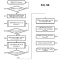
- FIG. 5B is flow diagram to graphically illustrate the flow process of a hardware powering-down sequence of the imaging modality 10 .
- the imaging modality has been in operative state (ON state) and is actively “running” normal imaging operations and third party applications.
- the power control circuit 260 acts as a “watchdog” in that at step S 512 it continuously monitors whether an OFF input is received. For example, the power control circuit 260 can detect whether the main power switch of the imaging modality 10 has been acted upon to turn the modality OFF.
- step S 514 the power control circuit 260 receives an OFF signal from the modality's ON/OFF board or switch.
- the power control circuit 260 checks the DC_in line of the first computer 210 (main computer). That is, in response to receiving the power OFF signal, the power control circuit 260 checks to see if the modality's computer is in an ON or OFF state.
- the power control circuit 260 detects a flag F 1 corresponding to an input sense line (senses the DC_in line) of the first computer 210 (modality's computer). If the DC_in line of the modality's computer exhibits a voltage potential equal to or greater than an established threshold (e.g., 5 VDC), it means that the first computer 210 (the modality's computer) is still in ON state (active state) and needs to be shutdown. If, on the other hand, the DC_in line of the modality's computer is at a voltage potential of 0 VDC or close thereto (lower than a threshold level), the modality's computer is already OFF. That is, at step S 518 , if the modality's computer is ON, the power control circuit 260 yields a positive result (YES), and the flow process advances to step S 520 .
- an established threshold e.g., 5 VDC
- step S 520 corresponding to time t 1 of FIG. 5A , the power control circuit 260 outputs a trigger signal (out 2 ) to turn the second computer 220 OFF.
- the power control circuit 260 checks the DC_in line of the second computer 220 until the DC_in line of second computer 220 exhibits a voltage potential of 0 VDC or close thereto (lower than a threshold level).
- the DC_in line of the second computer 220 is at 0 VDC or close thereto (YES at S 524 )
- the flow proceeds to S 526 .
- step S 526 corresponding to time t 2 in FIG.
- the power control circuit 260 outputs a trigger signal (out 1 ) to turn the first computer 210 (main computer) OFF.
- the power control circuit 260 is locked-out for a period of time sufficient to allow for both computers to respectively run their OS shutdown routines. This period of time is indicated as “Delay Td” from time t 2 to time t 3 in FIG. 5A .
- the power generator of the modality turns OFF; the power supply line PS of the first computer C 1 goes low to 0 VDC, as shown after time t 3 in FIG. 5A .
- a signal is sent to the shared computer power supply to shutdown.
- a signal is sent to the modality to turn the modality OFF. This, in turn, turns OFF the DC/AC inverter at step S 532 .
- An optional acknowledgment or OFF signal can be issued to inform the user of safe shutdown at step S 534 .
- a software application compatible with the operating system of master computer can be installed as a plug-in application running on the master computer.
- the software application runs as a Windows® service and implements an event handler (OnShutdown) that captures the Windows message “WM_QUERYENDSESSION” which is triggered by the modality's operator via either (a) Windows shutdown command (e.g. start->shutdown) or (b) imaging system shutdown (e.g. CXDI NE application shutdown).
- Windows shutdown command e.g. start->shutdown
- imaging system shutdown e.g. CXDI NE application shutdown.
- the start of the power-down routine is controlled by the software application that will continually monitor the operating system (OS) of the master computer for incoming messages in reference to a power-down (turn OFF) command. If a shutdown message is received, a call to the Smart Switch will be made via serial port communication protocol.
- the software application communicates with the power control circuit 260 by using the .NET SerialPort class via the second computer.
- the power control circuit 260 initiates the shutdown sequence as described below. That is, when a shutdown command is issued by the main computer, the command is forwarded to the slave or second computer via the direct communication link 215 (see FIG. 2A ), and power control circuit 260 senses the status of the two computers in a manner similar to the hardware power-down case.
- FIG. 6A is a timing diagram and FIG. 6B is flow chart to graphically illustrate an exemplary process of a software-initiated powering-down sequence of the multicomputer system.
- signal levels are substantially the same as those described with reference to FIG. 4A . Therefore, repetitious description thereof is omitted.
- the modality's main power operating system or imaging application receive a command (Turn OFF command) entered by the modality's operator. In this case, the command is to switch from an active (ON) state to a non-active (OFF) state.
- the software shutdown detected on the main or first computer activates a signal sent to the second computer via serial port communication. Both computers are now in shutdown mode.
- the smart switch SSW detects 0 v flags indicating that both motherboards are in a power OFF state.
- the smart switch SSW now sends a signal to the computer power supply to turn it OFF.
- the power supply now turns itself OFF.
- the software application communicates with the power control circuit 260 by using the .NET SerialPort class via the second computer.
- the power control circuit 260 initiates the shutdown sequence. To that end, the power control circuit 260 checks the input flag F 1 of the first computer by sensing the 5 VDC line of the first computer 210 (master computer). Since the first computer is still in operative (ON) state, a momentary short “short 1 ” causes the power control circuit 260 to check the flag F 2 of the second computer 220 , by also sensing the DC input line.
- FIG. 6B is a flow diagram to graphically illustrate the process of a software powering-down sequence of the multicomputer system.
- the imaging modality has been in operative state (ON state) and is actively “running” normal operations.
- the power control circuit 260 acts as a “watchdog” in that the step S 602 is continuously repeated to monitor whether a power-down system call is received from the operating system of the first computer 210 (master computer).
- the power-down system call may be issued by the operating system of the slave computer (second computer 220 ), for safety reasons it is preferable that the power-down system call is started by the first computer 210 (i.e., the computer that controls the imaging modality). In this manner, it can be ensured that the imaging modality ends all imaging operations prior to shutting its computer down.
- step S 604 the power control circuit 260 receives an OFF signal from the operating system of the modality's computer.
- step S 606 the power control circuit 260 checks the DC_in line of the main computer. That is, in response to receiving the power OFF system call, the power control circuit 260 checks to see if the modality's computer is in an ON or OFF state. To that end, at step S 608 , the power control circuit 260 detects the flag F 1 corresponding to an input sense line (senses the DC_in line) of the modality's computer.
- the DC_in line of the modality's computer exhibits a voltage potential equal to or greater than an established threshold value (e.g., 5 VDC), it means that the first computer 210 (the modality's computer) is still in ON state (active state) and needs to be shutdown. If, on the other hand, the DC_in line of the modality's computer is at a voltage potential of 0 VDC or close thereto (lower than a threshold level), the modality's computer is already OFF. Therefore, at step S 608 , if the modality's computer is ON, the power control circuit 260 yields a positive result (YES), and the flow process advances to step S 610 .
- an established threshold value e.g., 5 VDC
- the power control circuit 260 outputs a trigger signal (out 2 ) to turn the second computer 220 OFF; this is represented by the arrows at time t 1 in FIG. 6A .
- the power control circuit 260 checks the DC_in line of the second computer 220 until the DC_in line of the second computer 220 exhibits a voltage potential of 0 VDC or close thereto (lower than a threshold level).
- the DC_in line of the second computer 220 is at 0 VDC or close thereto (YES at S 614 )
- the flow proceeds to S 616 .
- step S 616 once the second computer (slave computer) is in the process of turning OFF, the power control circuit 260 outputs a trigger signal (out 1 ) to turn the first computer 210 (main computer) OFF; this is shown by the arrows at t 2 in FIG. 6B .
- the power control circuit 260 is locked-out for a period of time sufficient to allow both computers to respectively run their OS shutdown routines. This period of time is shown as “Delay Td” between time t 2 and t 3 in FIG. 6A .
- step S 620 or time t 3 in FIG. 6B , the power generator of the modality turns OFF.
- the power supply signal PS goes low to about 0 VDC. This, in turn, turns OFF the DC/AC inverter at step S 622 . At this time, an optional acknowledgment or OFF signal can be issued to inform the user of the safe powering down sequence at step S 624 .
- FIG. 7 is a flow diagram which illustrates an exemplary flow process for operating the multicomputer modality in a workflow scenario.
- An exemplary workflow scenario with the multicomputer modality as described above may take place as follows.
- an operator technologist
- the operator would, at step S 702 , login into the modality's interface, for example provide credential as an authorized user of the modality.
- the operator would login into modality 10 through the CXDI NE login screen.
- the operator uses the toggle switch TSW to switch from the main computer to the second computer (slave computer) interface to access third party applications. For example, the operator clicks on a toggle switch labeled X-Ray/Workstation to access third party applications.
- the operator searches, for example, in a Cerner® application for a patient order (S 706 ), and therein the operator can “Start” a patient's exam.
- the operator may again use the toggle switch TSW, e.g., the operator clicks on the switch labeled X-Ray/Workstation to switch back to the main computer (first computer) to access the modality's application (e.g., CXDI NE application).
- the operator may activate the modality for examination procedure, by setting exam parameters and preparing a subject for examination (S 710 ).
- step S 712 continuing to use the modality's application (main computer interface), the operator proceed to perform an imaging operation.
- an exam type body part protocol
- An imaging operation may require one or more images to be taken. For example, in an X-ray imaging modality, after one or more exposures are taken, and if everything looks acceptable on the mobile the exam is ended.
- the operator may once more use the toggle switch TSW, for example the operator clicks on a switch labeled EMR/PACS to access the third party applications interface on the slave computer.
- the operator accesses third party applications. For example, the operator may login into a healthcare facility's Agfa Impax PACS. Therein, the operator performs quality control of the exam just completed, by evaluating the images sent to PACS. The images are transferred to PACS from the first or main computer during DICOM transmission after the end of a study. The technician then does a Q.C. of the images ensuring all images have been successfully sent and all images have sufficient image quality. If all the images have been sent and all images look good (YES at S 718 ), the operator proceeds to end the exam (S 720 ). If the exam results are not satisfactory (NO at S 718 ), the operator would seamlessly switch back to the modality's application (main computer). Therefore, the flow process returns to S 708 , and the operator would repeat steps S 708 to S 710 until satisfactory exam results are obtained.
- the operator may safely end the exam. Then the operator would log out from one third party application and a second third party application, if necessary (S 722 ). For example, the operator may log out of Agfa Impax and log into the Cerner application, where the patient is searched for and the study is closed. Thereafter, the operator may switch back to the modality's application (S 724 ) to safely shutdown the imaging modality (S 726 ) using the system software shutdown routine. Alternatively, the operator may choose to use the hardware shutdown routine directly at step S 722 , by operating a power OFF button on the imaging modality. In this case, the power control circuit 260 will ensure a safe shutdown sequence in accordance with the flow of FIG. 5B .
- Some of the advantages of implementing an imaging modality with plural computer in the manner described above include, but are not limited to, (a) the ability to maintain the imaging modality in its original government-approved state, which ensures system performance and compliance, (b) the ability to run required third party software application without interfering with the modality's original software running in the modality's master computer, (c) the operating system of the second computer can be independent from that used in the modality's computer, indeed even open source operating systems or software applications can be freely installed in the slave computer, (d) the ability to install and run third party applications directly from the imaging modality is seen as an important aspect for vendors of third party applications which run on legacy platforms no longer supported by newer operating systems, (d) the ability to run third party applications directly from the imaging modality will contribute to streamline the workflow of medical imaging, will increase the productivity of imaging technicians, and alleviate patients of unnecessary burdens.
Landscapes
- Health & Medical Sciences (AREA)
- Engineering & Computer Science (AREA)
- Life Sciences & Earth Sciences (AREA)
- Medical Informatics (AREA)
- Biomedical Technology (AREA)
- Public Health (AREA)
- General Health & Medical Sciences (AREA)
- Heart & Thoracic Surgery (AREA)
- High Energy & Nuclear Physics (AREA)
- Pathology (AREA)
- Radiology & Medical Imaging (AREA)
- Nuclear Medicine, Radiotherapy & Molecular Imaging (AREA)
- Physics & Mathematics (AREA)
- Molecular Biology (AREA)
- Surgery (AREA)
- Animal Behavior & Ethology (AREA)
- Optics & Photonics (AREA)
- Biophysics (AREA)
- Veterinary Medicine (AREA)
- Computer Networks & Wireless Communication (AREA)
- Business, Economics & Management (AREA)
- General Business, Economics & Management (AREA)
- Epidemiology (AREA)
- Primary Health Care (AREA)
- Apparatus For Radiation Diagnosis (AREA)
Abstract
Description
Claims (20)
Priority Applications (1)
| Application Number | Priority Date | Filing Date | Title |
|---|---|---|---|
| US14/200,976 US9456799B2 (en) | 2013-03-08 | 2014-03-07 | Modality with multicomputer system and powering sequence therefor |
Applications Claiming Priority (2)
| Application Number | Priority Date | Filing Date | Title |
|---|---|---|---|
| US201361775358P | 2013-03-08 | 2013-03-08 | |
| US14/200,976 US9456799B2 (en) | 2013-03-08 | 2014-03-07 | Modality with multicomputer system and powering sequence therefor |
Publications (2)
| Publication Number | Publication Date |
|---|---|
| US20140254769A1 US20140254769A1 (en) | 2014-09-11 |
| US9456799B2 true US9456799B2 (en) | 2016-10-04 |
Family
ID=51487824
Family Applications (1)
| Application Number | Title | Priority Date | Filing Date |
|---|---|---|---|
| US14/200,976 Expired - Fee Related US9456799B2 (en) | 2013-03-08 | 2014-03-07 | Modality with multicomputer system and powering sequence therefor |
Country Status (1)
| Country | Link |
|---|---|
| US (1) | US9456799B2 (en) |
Cited By (4)
| Publication number | Priority date | Publication date | Assignee | Title |
|---|---|---|---|---|
| US20180116615A1 (en) * | 2015-07-31 | 2018-05-03 | Fujifilm Corporation | Radiation-irradiation device |
| US20180125439A1 (en) * | 2015-07-16 | 2018-05-10 | Fujifilm Corporation | Radiographic imaging apparatus |
| US20180146940A1 (en) * | 2015-07-27 | 2018-05-31 | Fujifilm Corporation | Radiation-irradiation device |
| US20180270938A1 (en) * | 2016-08-03 | 2018-09-20 | Samsung Electronics Co., Ltd. | Mobile x-ray apparatus including a battery management system |
Families Citing this family (5)
| Publication number | Priority date | Publication date | Assignee | Title |
|---|---|---|---|---|
| JP6476879B2 (en) * | 2015-01-15 | 2019-03-06 | コニカミノルタ株式会社 | Mobile X-ray apparatus and box |
| US9568970B1 (en) * | 2015-02-12 | 2017-02-14 | Netspeed Systems, Inc. | Hardware and software enabled implementation of power profile management instructions in system on chip |
| US10169562B2 (en) * | 2015-08-27 | 2019-01-01 | International Business Machines Corporation | Activity recognition to confirm secure authentication of a user |
| US10444810B2 (en) * | 2017-05-03 | 2019-10-15 | Amzetta Technologies, Llc | System and method for automatic power control and unusual activity detections for thin client computing devices |
| JP7571506B2 (en) * | 2020-12-03 | 2024-10-23 | コニカミノルタ株式会社 | Radiation image capturing apparatus, radiation image capturing system, control method and control program |
Citations (18)
| Publication number | Priority date | Publication date | Assignee | Title |
|---|---|---|---|---|
| US5680536A (en) * | 1994-03-25 | 1997-10-21 | Tyuluman; Samuel A. | Dual motherboard computer system |
| US5828140A (en) * | 1995-11-03 | 1998-10-27 | Shih; Steven | Redundant power controller |
| US20020004915A1 (en) | 1990-06-01 | 2002-01-10 | Amphus, Inc. | System, method, architecture, and computer program product for dynamic power management in a computer system |
| US6557170B1 (en) * | 1997-05-05 | 2003-04-29 | Cybex Computer Products Corp. | Keyboard, mouse, video and power switching apparatus and method |
| US6661123B2 (en) | 2001-12-17 | 2003-12-09 | Mitac International Corp. | Power control circuit with power-off time delay control for microprocessor-based system |
| US20070007824A1 (en) | 2005-07-11 | 2007-01-11 | Asrock Inc. | DC uninterruptible power supply and computer device using the same |
| US20090158057A1 (en) | 2007-12-14 | 2009-06-18 | International Business Machines Corporation | System and method for interchangeably powering single or multiple motherboards |
| US20090177901A1 (en) * | 2008-01-08 | 2009-07-09 | Aten International Co., Ltd. | Kvm management system capable of controlling computer power |
| US20090217064A1 (en) * | 2008-02-27 | 2009-08-27 | Fujitsu Component Limited | Power supply controlling apparatus and power supply controlling system |
| US20090230781A1 (en) | 2008-03-12 | 2009-09-17 | Hon Hai Precision Industry Co., Ltd. | Switching power supply saving system |
| US20090265412A1 (en) | 2008-03-03 | 2009-10-22 | Eric Hainzer | Plural Computer System |
| US20110018342A1 (en) | 2009-07-24 | 2011-01-27 | Seung Hoon Park | Direct tie-in of a common backup power source to motherboards in a server system |
| US20120013186A1 (en) | 2010-07-16 | 2012-01-19 | Pierluigi Sarti | Power supply unit directly connected to backup direct current power source |
| US20120191990A1 (en) * | 2009-12-05 | 2012-07-26 | Hewlett-Packard Development Company, L.P. | Systems apparatus and methods blocking a power transition |
| US8281167B2 (en) * | 2008-01-11 | 2012-10-02 | Denso Corporation | Electronic control apparatus provided with plural microcomputers for electronically controlling electronic devices mounted in vehicle |
| US8314805B2 (en) | 2008-01-02 | 2012-11-20 | Beijing Lenovo Software Ltd. | Control method and computer system for switching display between OSs |
| US20120293017A1 (en) * | 2011-04-25 | 2012-11-22 | Volterra Semiconductor Corporation | Integrated protection devices with monitoring of electrical characteristics |
| US20130103934A1 (en) * | 2011-10-21 | 2013-04-25 | Hitachi, Ltd. | Computer system and method for taking over module therein |
-
2014
- 2014-03-07 US US14/200,976 patent/US9456799B2/en not_active Expired - Fee Related
Patent Citations (18)
| Publication number | Priority date | Publication date | Assignee | Title |
|---|---|---|---|---|
| US20020004915A1 (en) | 1990-06-01 | 2002-01-10 | Amphus, Inc. | System, method, architecture, and computer program product for dynamic power management in a computer system |
| US5680536A (en) * | 1994-03-25 | 1997-10-21 | Tyuluman; Samuel A. | Dual motherboard computer system |
| US5828140A (en) * | 1995-11-03 | 1998-10-27 | Shih; Steven | Redundant power controller |
| US6557170B1 (en) * | 1997-05-05 | 2003-04-29 | Cybex Computer Products Corp. | Keyboard, mouse, video and power switching apparatus and method |
| US6661123B2 (en) | 2001-12-17 | 2003-12-09 | Mitac International Corp. | Power control circuit with power-off time delay control for microprocessor-based system |
| US20070007824A1 (en) | 2005-07-11 | 2007-01-11 | Asrock Inc. | DC uninterruptible power supply and computer device using the same |
| US20090158057A1 (en) | 2007-12-14 | 2009-06-18 | International Business Machines Corporation | System and method for interchangeably powering single or multiple motherboards |
| US8314805B2 (en) | 2008-01-02 | 2012-11-20 | Beijing Lenovo Software Ltd. | Control method and computer system for switching display between OSs |
| US20090177901A1 (en) * | 2008-01-08 | 2009-07-09 | Aten International Co., Ltd. | Kvm management system capable of controlling computer power |
| US8281167B2 (en) * | 2008-01-11 | 2012-10-02 | Denso Corporation | Electronic control apparatus provided with plural microcomputers for electronically controlling electronic devices mounted in vehicle |
| US20090217064A1 (en) * | 2008-02-27 | 2009-08-27 | Fujitsu Component Limited | Power supply controlling apparatus and power supply controlling system |
| US20090265412A1 (en) | 2008-03-03 | 2009-10-22 | Eric Hainzer | Plural Computer System |
| US20090230781A1 (en) | 2008-03-12 | 2009-09-17 | Hon Hai Precision Industry Co., Ltd. | Switching power supply saving system |
| US20110018342A1 (en) | 2009-07-24 | 2011-01-27 | Seung Hoon Park | Direct tie-in of a common backup power source to motherboards in a server system |
| US20120191990A1 (en) * | 2009-12-05 | 2012-07-26 | Hewlett-Packard Development Company, L.P. | Systems apparatus and methods blocking a power transition |
| US20120013186A1 (en) | 2010-07-16 | 2012-01-19 | Pierluigi Sarti | Power supply unit directly connected to backup direct current power source |
| US20120293017A1 (en) * | 2011-04-25 | 2012-11-22 | Volterra Semiconductor Corporation | Integrated protection devices with monitoring of electrical characteristics |
| US20130103934A1 (en) * | 2011-10-21 | 2013-04-25 | Hitachi, Ltd. | Computer system and method for taking over module therein |
Non-Patent Citations (3)
| Title |
|---|
| Adams, "Microwulf: A Personal, portable Beowulf Cluster", Microwulf Design, Apr. 12, 2013, pp. 1-2, www.calvin.edu/~adams/research/microwulf/design/. |
| Adams, "Microwulf: A Personal, portable Beowulf Cluster", Microwulf Design, Apr. 12, 2013, pp. 1-2, www.calvin.edu/˜adams/research/microwulf/design/. |
| Bursky, et al."Securing a Multicore, Dual OS, Wireless Medical Platform", Embedded Intel, Apr. 25, 2013; pp. 1-5. |
Cited By (8)
| Publication number | Priority date | Publication date | Assignee | Title |
|---|---|---|---|---|
| US20180125439A1 (en) * | 2015-07-16 | 2018-05-10 | Fujifilm Corporation | Radiographic imaging apparatus |
| US10993682B2 (en) * | 2015-07-16 | 2021-05-04 | Fujifilm Corporation | Radiographic imaging apparatus comprising a leg unit having three or more wheel units |
| US20180146940A1 (en) * | 2015-07-27 | 2018-05-31 | Fujifilm Corporation | Radiation-irradiation device |
| US10765388B2 (en) * | 2015-07-27 | 2020-09-08 | Fujifilm Corporation | Radiation-irradiation device comprising a first arm, a second arm, and main body surface regulating a rotational movement of the second arm |
| US20180116615A1 (en) * | 2015-07-31 | 2018-05-03 | Fujifilm Corporation | Radiation-irradiation device |
| US10856821B2 (en) * | 2015-07-31 | 2020-12-08 | Fujifilm Corporation | Radiation-irradiation device including a cradle that supports an edge portion of a radiation detector |
| US20180270938A1 (en) * | 2016-08-03 | 2018-09-20 | Samsung Electronics Co., Ltd. | Mobile x-ray apparatus including a battery management system |
| US10652988B2 (en) * | 2016-08-03 | 2020-05-12 | Samsung Electronics Co., Ltd. | Mobile x-ray apparatus including a battery management system |
Also Published As
| Publication number | Publication date |
|---|---|
| US20140254769A1 (en) | 2014-09-11 |
Similar Documents
| Publication | Publication Date | Title |
|---|---|---|
| US9456799B2 (en) | Modality with multicomputer system and powering sequence therefor | |
| RU2571590C2 (en) | Remote monitoring system for monitoring medical devices via wireless communication systems | |
| CN107920792B (en) | Systems and methods for X-ray imaging alignment | |
| JP2022105331A (en) | Method and system for communication between monitoring client and base | |
| US10380321B2 (en) | System, method, and apparatus for electronic patient care | |
| US10558667B2 (en) | System and method of healthcare data management | |
| RU2672020C2 (en) | Monitor defibrillator telemedicine server | |
| US10957091B1 (en) | Perioperative mobile communication system and method | |
| CN109100374B (en) | X-ray imaging detector with study data functionality | |
| US9031194B2 (en) | X-ray imaging apparatus, method for X-ray imaging apparatus and non-transitory computer-readable recording medium | |
| JP5976378B2 (en) | Medical device management system and medical device management program | |
| JP6885997B2 (en) | Systems, methods, and equipment for electronic patient care | |
| KR102295627B1 (en) | Method for Providing Preliminary Questionnaire Drafting and System Thereof | |
| US20130336457A1 (en) | Radiography control apparatus and radiography control method | |
| JP2016126427A (en) | Medical support device, system, program and method | |
| US20240266028A1 (en) | Device, system, and method for determining a reading environment by synthesizing downstream needs | |
| US20210075770A1 (en) | Method and apparatus for data communication in a network | |
| JP7210254B2 (en) | Medical data file generation device, medical data file generation system, and medical data file generation program | |
| JP7735082B2 (en) | Medical image processing equipment | |
| JP2008229244A (en) | Medical imaging system | |
| CN104217383A (en) | Status notification method for medical reports of patients | |
| US20240161920A1 (en) | Medical information processing apparatus and medical information processing system | |
| US20240071584A1 (en) | Medical information system and medical image diagnostic device | |
| JP2020034977A (en) | Operation cooperation terminal, image interpretation report creation cooperation system, image interpretation report creation cooperation program, and operation cooperation program | |
| US20240095914A1 (en) | Interpretation management apparatus, interpretation management system, image management apparatus, interpretation terminal, analysis apparatus, interpretation management method, and recording medium |
Legal Events
| Date | Code | Title | Description |
|---|---|---|---|
| AS | Assignment |
Owner name: VIRTUAL IMAGING, INC., FLORIDA Free format text: ASSIGNMENT OF ASSIGNORS INTEREST;ASSIGNORS:CHICCHETTI, PETER M;PIZZUTO, CARMINE;REEL/FRAME:034027/0595 Effective date: 20141017 |
|
| STCF | Information on status: patent grant |
Free format text: PATENTED CASE |
|
| MAFP | Maintenance fee payment |
Free format text: PAYMENT OF MAINTENANCE FEE, 4TH YEAR, LARGE ENTITY (ORIGINAL EVENT CODE: M1551); ENTITY STATUS OF PATENT OWNER: LARGE ENTITY Year of fee payment: 4 |
|
| AS | Assignment |
Owner name: CANON MEDICAL SYSTEMS USA, INC., CALIFORNIA Free format text: MERGER;ASSIGNOR:VIRTUAL IMAGING, INC.;REEL/FRAME:054341/0548 Effective date: 20191223 |
|
| AS | Assignment |
Owner name: CANON MEDICAL SYSTEMS CORPORATION, JAPAN Free format text: ASSIGNMENT OF ASSIGNORS INTEREST;ASSIGNOR:CANON MEDICAL SYSTEMS USA, INC.;REEL/FRAME:054503/0257 Effective date: 20200630 |
|
| FEPP | Fee payment procedure |
Free format text: MAINTENANCE FEE REMINDER MAILED (ORIGINAL EVENT CODE: REM.); ENTITY STATUS OF PATENT OWNER: LARGE ENTITY |
|
| LAPS | Lapse for failure to pay maintenance fees |
Free format text: PATENT EXPIRED FOR FAILURE TO PAY MAINTENANCE FEES (ORIGINAL EVENT CODE: EXP.); ENTITY STATUS OF PATENT OWNER: LARGE ENTITY |
|
| STCH | Information on status: patent discontinuation |
Free format text: PATENT EXPIRED DUE TO NONPAYMENT OF MAINTENANCE FEES UNDER 37 CFR 1.362 |
|
| FP | Lapsed due to failure to pay maintenance fee |
Effective date: 20241004 |