US944429A - Hydraulic brake. - Google Patents
Hydraulic brake. Download PDFInfo
- Publication number
- US944429A US944429A US51541609A US1909515416A US944429A US 944429 A US944429 A US 944429A US 51541609 A US51541609 A US 51541609A US 1909515416 A US1909515416 A US 1909515416A US 944429 A US944429 A US 944429A
- Authority
- US
- United States
- Prior art keywords
- casing
- valve
- disk
- chamber
- shaft
- Prior art date
- Legal status (The legal status is an assumption and is not a legal conclusion. Google has not performed a legal analysis and makes no representation as to the accuracy of the status listed.)
- Expired - Lifetime
Links
- 239000007788 liquid Substances 0.000 description 13
- 230000000979 retarding effect Effects 0.000 description 3
- 239000012530 fluid Substances 0.000 description 2
- 238000010438 heat treatment Methods 0.000 description 2
- 101000952982 Conus striatus Conopressin-S Proteins 0.000 description 1
- 101150004141 Vcan gene Proteins 0.000 description 1
- 238000010276 construction Methods 0.000 description 1
- 230000008878 coupling Effects 0.000 description 1
- 238000010168 coupling process Methods 0.000 description 1
- 238000005859 coupling reaction Methods 0.000 description 1
- 210000004907 gland Anatomy 0.000 description 1
- 239000004519 grease Substances 0.000 description 1
- 230000000717 retained effect Effects 0.000 description 1
Images

Classifications
-
- F—MECHANICAL ENGINEERING; LIGHTING; HEATING; WEAPONS; BLASTING
- F16—ENGINEERING ELEMENTS AND UNITS; GENERAL MEASURES FOR PRODUCING AND MAINTAINING EFFECTIVE FUNCTIONING OF MACHINES OR INSTALLATIONS; THERMAL INSULATION IN GENERAL
- F16D—COUPLINGS FOR TRANSMITTING ROTATION; CLUTCHES; BRAKES
- F16D57/00—Liquid-resistance brakes; Brakes using the internal friction of fluids or fluid-like media, e.g. powders
- F16D57/06—Liquid-resistance brakes; Brakes using the internal friction of fluids or fluid-like media, e.g. powders comprising a pump circulating fluid, braking being effected by throttling of the circulation
Definitions
- '.lhis invention relates to'that class of brakes which are designed to vary the speed lof common construction and its gate is raised and lowered to open and close the [luid way. by means of the stem S in the usual way.
- the disk Keyed upon the shaft in the chamber oi the casing is a disk t).
- the disk is circular and is mounted with its center coincident with the center ot' the shaft, while. the axes of the shaft and dlsk are locatedA eccentric of, or stop the rotation of a driven part, i
- the object of the invention is to provide a simple and eilici'ent brake of this character which is so constructed that the rotation of the driven part., shaft or axle, vcan be retarded to the desired degree, or completely stopped, as slowly or as uickly as'necessary, in a smooth and noise ess manner, and which has its pump pistons so controlled, by
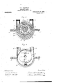
- Figure l 'of the accompanying drawings shows a front elevation, with part broken away, of a hydraulic braking apparatus which embodies this invention.
- Fig. 2 shows a side elevation of the same.
- Fig.- 3 shows a vertical section on the plane indicated by the dotted line 3-3 on Fig. 2.
- Fig. 4 sliowsavertical section through the casing on the plane denoted by the dotted line 4-4 on Fig.
- the driven'shaft or :axle l which is to be braked, or' which may be connected with the part to be controlled by the apparatusillustra'ted, extends through a liquid tightk cylindrical casing 2.
- the casing shown has flanges 3 by means of which-it may be secured in position.
- Projecting tangentially from the top edge of the casing are'two threaded hubs 4.
- These hubs, by couplings 5 and elbows 6, are connected with the opposite sides of a stop valve 7.
- This valve is pumped by the rotation of' with the center ot' the, 'cylindrical chamber in the casing.
- Movable radially in mortises in the periphery of the disk are piston blocks 10. At the outer ends these pistons have shoes 1.1 which are fitted to the vperipheral wall of the'chamber. Studs l2 project laterally'from one side of the pistons.
- levers are connected' by pin and slot joints with a yoke 19 that movably fastened v ⁇ to one face of the casing by screws 20 that extend through slots 21 in the yoke.
- the valve stem is connected with the yoke by means of the arm
- the end of the yoke is-designed to'bc connected with the lever or rod by means of which the device is operated.
- valve If the valve is open there is a free passage through it from one side'of the easing to the other. and if the valve is closed liquid canl not tiow through it fromone side ot the casing to the other.
- the valve is' opened and closed by the movement of the voke bar which is connected with the valve stem.
- . ⁇ ii apparatus forrt ai'fding orstopping a rotating part having a casingl with a evlindrieal chamber ajuda passage from one side 4otthe chan'ib'er to the other, a stop valve arranged tov control the low' ot' liquid through said. passage, a.l shaft extending through the casing eccentrically with respect to the chamber, a disk mounted Vcei'itrally on the shaft, pistons movable in the yperiphery ot' said t'lislgsiviteh' lingers movable in the easing vfor guiding'the pistons, and meansv connected with the valve and with the.
- An apparatus forretardingor'Ltopping a 'rotating part having a-Casing 'with' a cylindrical chamber and a tangential inlet on: one sideiand atangential outlet onthe other side, Ia stop valve,fittings connecting 85 .said valve With the' casing inlet andfoutlet,
- a Y rotating part, ⁇ having a casingV .-.wi'th a' cylindrical chamber and atpassage from one side of the chamber to the other,a stopjvalve v" arranged Vto control the flowfof the liquidi through said passage, a shaft extending, through the casing ecoentrically Witht, ref' ⁇ spect tothe, chamber, aV diskinounted Leen tiallvon the shaft, pistons movable ⁇ inlth periphery of Ythe disk, switch ,fingers mov- -ablein the .easing for guiding the pistons,I
Landscapes
- Engineering & Computer Science (AREA)
- General Engineering & Computer Science (AREA)
- Mechanical Engineering (AREA)
- Braking Arrangements (AREA)
Description
P. H. HALSTEAD.
HYDRAULIC BRAKE. APPLIGATION FILED AUG.31,'1909.
944,429, Patented 1360.28, 1909.
2 SHEETS-SHEET 1.
WXJW'. l
P. H. HALSTBAD.
HYDRAULIC BRAKE.
AAAAAAAAAAAAAAAAAAAAAAAAAA 9.
y l sssssssssss ET FREDERICK I-I. yI-IALS'IELAID. OF PITTSFIELD, MASSACHUSETTS.
HYDRAULIC BRAKE.
Specication of Letters Patent.
Patented Dec. 2S, 1.90).
Application led August 31, 1909. Serial No. 515,416.
T o all who/mI it may concer-n.'
Be it known that I, FREDERICK H. HAL- s'1r-:.\n, a citizen ofthe United States, residl ing at Pittsfield, in the county of Berkshire and State of Massachusetts, have invented a new and useful Improvement in Hydraulic Brakes. of which the following is a specification. l K
,'.lhis invention relates to'that class of brakes which are designed to vary the speed lof common construction and its gate is raised and lowered to open and close the [luid way. by means of the stem S in the usual way.
Keyed upon the shaft in the chamber oi the casing is a disk t). The disk is circular and is mounted with its center coincident with the center ot' the shaft, while. the axes of the shaft and dlsk are locatedA eccentric of, or stop the rotation of a driven part, i
such as the aXle'of a. car, automobile, or like vehicle, or the sha ftof an` engine, motor, dynamo or similar machine, or a line Vof shutting in aV shop or mill, by controlling the Howof, or stoppage of flow of, liquids, such as oil, or semi-liquids, such as grease or non-fluid oil, the driven part. n,
The object of the invention is to provide a simple and eilici'ent brake of this character which is so constructed that the rotation of the driven part., shaft or axle, vcan be retarded to the desired degree, or completely stopped, as slowly or as uickly as'necessary, in a smooth and noise ess manner, and which has its pump pistons so controlled, by
mechanism connected with the stop 'valve' that controls the liquid passage, that the liquid is quiescent when the parts are running normally andare not being used to etfectany braking or retarding action, thus eliminating fluid. friction and heating and reducing the expenditure of energy.
Figure l 'of the accompanying drawings shows a front elevation, with part broken away, of a hydraulic braking apparatus which embodies this invention. Fig. 2 shows a side elevation of the same. Fig.- 3 shows a vertical section on the plane indicated by the dotted line 3-3 on Fig. 2. Fig. 4 sliowsavertical section through the casing on the plane denoted by the dotted line 4-4 on Fig.
The driven'shaft or :axle l which is to be braked, or' which may be connected with the part to be controlled by the apparatusillustra'ted, extends through a liquid tightk cylindrical casing 2. The casing shown has flanges 3 by means of which-it may be secured in position. Projecting tangentially from the top edge of the casing are'two threaded hubs 4. These hubs, by couplings 5 and elbows 6, are connected with the opposite sides of a stop valve 7. This valve is pumped by the rotation of' with the center ot' the, 'cylindrical chamber in the casing. Movable radially in mortises in the periphery of the disk are piston blocks 10. At the outer ends these pistons have shoes 1.1 which are fitted to the vperipheral wall of the'chamber. Studs l2 project laterally'from one side of the pistons.
Ina recess in the face ot' the casing at one sideof'the circular piston chamber. are a pair of curved switch fingers 1:3.' The outer walls 'of the tii1gers-aretormed on the arc of acircle the center of which is coincident with the center of the circularl piston cham-- ber in the casing. and the inner walls of the lingers are formed on the arc of a circle. the center of which is coincident with the center of the piston disk.` At the larger ends these fingers are pivotally retained in place by laterally extending stems 14.' Each stem..in' a gland 15, is connected by a spring 1G with a block 1T that is secured tothe end otl a lever 148. lThese levers are connected' by pin and slot joints with a yoke 19 that movably fastened v`to one face of the casing by screws 20 that extend through slots 21 in the yoke. The valve stem is connected with the yoke by means of the arm The end of the yoke is-designed to'bc connected with the lever or rod by means of which the device is operated.
If the valve is open there is a free passage through it from one side'of the easing to the other. and if the valve is closed liquid canl not tiow through it fromone side ot the casing to the other. The valve is' opened and closed by the movement of the voke bar which is connected with the valve stem.
' Themovement of the yoke, through the levers 1 8. and springs 16 swings thc switch fingers. The parts are so designed that the switch tingers are swung when the `valve' starts to move. the spring connections yield` ing, after the lingers 'are swung, to permit further movement of the valve.
When the valve is opened the fingers are swung to the posit-ions illustrated by the v iliepistons to pump liquid or semi-liquitlv y heating of the liquid when the driven shaft-V p is running tree andl consequentlyV economizes liowever, as soon asthe valve eoin-y dotted lines in Fig. 3, then, the studs'lQ, that'l project 'from the piston blot-ks, are
guided by the fingers so as yto travel in the circular groove Q3, and the center ot' this groove being coincident with the axisof the piston' disk the piston blocks are 'held vretracted 'in the disk, and consequently do not workl'that'is, pump noliquid and exert no relai-ding or braking action as the disk rotates. ll'hen the valvesis closed orpartly rloscdfthe fingers are swung to the positions illustrated bythe full linesin Fig. then the studs 'l2 are guided so as to travel in the -grooi'e 24.
As the renter ot' this groove is coincident with the center of the piston chamber and eccentric with thecenterof the diskthe pistons are caused to travel with' their slices in contactwith thev 'wallet the chamber. as shown in Fig. 4. Under these conditions the rotation ot' 'therdisk causes mattei. with which the -asing is filled, from ontl side to the otlierQand ifvtheilow of hquid is restricted or stopped bv thevalye the" rotation oi" the disk is retarded Vor entirely stopi'ied.: As thepistons are heldV retracted when the vvalve is open they do no work, allowing 'the' liquid to remain quiescent as the disk rotated when nobraking action is required. This eliminates friction and a cylindi'it-al chambe and a passage from :one side ot the chamber to the other` a stop valve arranged to control the How ot' liquid tl'n'oughA said passage, a` shaft extending Ythrough the'casing eeccntrieally with respect to thel chamber, adisk mounted'centrally 4on the shaft, pistons movable iii the periph-` er)r ofthe said disk, switch lingers Inovable in the casing fory guiding the pistons, and means for throwfingthe'said fingers.
.\ii apparatus forrt ai'fding orstopping a rotating part, having a casingl with a evlindrieal chamber ajuda passage from one side 4otthe chan'ib'er to the other, a stop valve arranged tov control the low' ot' liquid through said. passage, a.l shaft extending through the casing eccentrically with respect to the chamber, a disk mounted Vcei'itrally on the shaft, pistons movable in the yperiphery ot' said t'lislgsiviteh' lingers movable in the easing vfor guiding'the pistons, and meansv connected with the valve and with the.
switch lingers vwhereby the movement ofV said means ii'ioves the 'valve vand fingers; `siniultaneouslyr f' 'valve arranged'to control the flow of. liquid.
'3.' An apparat its tor reta .lingl'or stopping j aV rotating part, having a easing with a l tgvlindrital elianiber'and a passage from one side ot' the, chamber to the. other,-'ag stop` through saidpassage, a shaft extending; through the casingY eecentrica'lly''V with respect to thechainber, afdisk,mounted;centrally on the shaft,v pistonsV movable .in theiperiplieryu E ol. said disk, switeh'fingers Ynitwable infthe casing'for guiding vthe.pistons,.fle\ers con-S nected with Ythe iineers, a vokc'inovabl ont one face of` the casing, and ineans connect# ing the yoke and th'eval've and the lYoke and the switch levers. n Y
4. An apparatus forretardingor'Ltopping a 'rotating part, having a-Casing 'with' a cylindrical chamber and a tangential inlet on: one sideiand atangential outlet onthe other side, Ia stop valve,fittings connecting 85 .said valve With the' casing inlet andfoutlet,
a shaft extending' through the casing eceentrically. with respect to the clianiberga disk' mounted centrally' on 'tlie'shaft,gpiston`s in'ovjable in the peripheryofthe disk, ineanslfo'r 970V guiding 'the pistons, and means. connected with said guiding meha-nsrand; withthe valve j whereby they are moved coinoidently.1
5. An apparatus for retarding or stopping. a Y rotating part,` having a casingV .-.wi'th a' cylindrical chamber and atpassage from one side of the chamber to the other,a stopjvalve v" arranged Vto control the flowfof the liquidi through said passage, a shaft extending, through the casing ecoentrically Witht, ref'` spect tothe, chamber, aV diskinounted Leen tiallvon the shaft, pistons movable` inlth periphery of Ythe disk, switch ,fingers mov- -ablein the .easing for guiding the pistons,I
a )'Oke'niovable onl one face ofi the-.casing and connected with the valve, leversconj-" -nected withthc yoke, andr springs connecting the levers with the switch fingers. V I V 6." An apparatus for retarding or stopping a rotating part,` havingy a oasingnvith Va,
ll cylindrical chamber and apassage from one Y side of the chamber to'the'other, 'a stop ,valve 'arranged tofcontrol theilox'v-ofthe liquid 1 `t'liipughf Y said passa ge, Y aY shaft'r ,extending through the casing,eeeentricallv with respee lon `the shaft, piston blocks nioval'ile 11i the disk, bearlng sl1oesj`n'iounted,in theV ends of said bloeksfswitch fingers movable in vthe 'easing for .guiding'the pistons, and 120.7
11:5 Y' Vto the' chamber, a disk mountedcentrally,
Priority Applications (1)
| Application Number | Priority Date | Filing Date | Title |
|---|---|---|---|
| US51541609A US944429A (en) | 1909-08-31 | 1909-08-31 | Hydraulic brake. |
Applications Claiming Priority (1)
| Application Number | Priority Date | Filing Date | Title |
|---|---|---|---|
| US51541609A US944429A (en) | 1909-08-31 | 1909-08-31 | Hydraulic brake. |
Publications (1)
| Publication Number | Publication Date |
|---|---|
| US944429A true US944429A (en) | 1909-12-28 |
Family
ID=3012851
Family Applications (1)
| Application Number | Title | Priority Date | Filing Date |
|---|---|---|---|
| US51541609A Expired - Lifetime US944429A (en) | 1909-08-31 | 1909-08-31 | Hydraulic brake. |
Country Status (1)
| Country | Link |
|---|---|
| US (1) | US944429A (en) |
Cited By (1)
| Publication number | Priority date | Publication date | Assignee | Title |
|---|---|---|---|---|
| US2900060A (en) * | 1955-08-24 | 1959-08-18 | Ernest E Wagner | Variable speed constant torque fluid drive |
-
1909
- 1909-08-31 US US51541609A patent/US944429A/en not_active Expired - Lifetime
Cited By (1)
| Publication number | Priority date | Publication date | Assignee | Title |
|---|---|---|---|---|
| US2900060A (en) * | 1955-08-24 | 1959-08-18 | Ernest E Wagner | Variable speed constant torque fluid drive |
Similar Documents
| Publication | Publication Date | Title |
|---|---|---|
| US1779757A (en) | Hydraulic change-speed gearing | |
| US2164876A (en) | Hydraulic vane motor | |
| US2260406A (en) | Governor for automatic transmission | |
| US2117673A (en) | Hydraulic transmission | |
| US2126751A (en) | Hydrodynamic brake | |
| US3011449A (en) | Vaned hydraulic unit | |
| US2433651A (en) | Power steering gear | |
| US2280897A (en) | Fluid controlled brake | |
| US2382114A (en) | Hydraulic coupling | |
| US2416638A (en) | Hydraulic brake mechanism | |
| US2075812A (en) | Valve and control therefor | |
| US2307506A (en) | Hydraulic coupling | |
| US2552167A (en) | Vane type fluid drive | |
| US2376016A (en) | Pump | |
| US1501444A (en) | Hydraulic brake | |
| US1866424A (en) | Emptying device for liquid couplings | |
| US2255782A (en) | Fluid pressure means and system | |
| US2515288A (en) | Expansible chamber rotary motor of the sliding abutment type | |
| US1599439A (en) | Hydraulic brake | |
| US2118808A (en) | Hydraulic brake | |
| US3075598A (en) | Power transfer device | |
| US2797643A (en) | Hydraulic pump structure | |
| US2790519A (en) | Fluid brake | |
| US2551249A (en) | Speed regulating hydraulic clutch | |
| US1922423A (en) | Fluid meter |