US9442444B2 - Fixing device and image forming apparatus - Google Patents
Fixing device and image forming apparatus Download PDFInfo
- Publication number
- US9442444B2 US9442444B2 US15/014,067 US201615014067A US9442444B2 US 9442444 B2 US9442444 B2 US 9442444B2 US 201615014067 A US201615014067 A US 201615014067A US 9442444 B2 US9442444 B2 US 9442444B2
- Authority
- US
- United States
- Prior art keywords
- sheet
- nip part
- recording medium
- nip
- fixing device
- Prior art date
- Legal status (The legal status is an assumption and is not a legal conclusion. Google has not performed a legal analysis and makes no representation as to the accuracy of the status listed.)
- Expired - Fee Related
Links
- 238000003825 pressing Methods 0.000 claims abstract description 93
- 230000007423 decrease Effects 0.000 claims abstract description 19
- 238000005452 bending Methods 0.000 claims abstract description 14
- 230000007246 mechanism Effects 0.000 claims description 23
- 238000001514 detection method Methods 0.000 claims description 13
- 230000005489 elastic deformation Effects 0.000 description 13
- 229910052736 halogen Inorganic materials 0.000 description 10
- 150000002367 halogens Chemical class 0.000 description 10
- 230000005855 radiation Effects 0.000 description 7
- 230000003247 decreasing effect Effects 0.000 description 5
- 239000003086 colorant Substances 0.000 description 4
- 238000011282 treatment Methods 0.000 description 4
- 230000005540 biological transmission Effects 0.000 description 3
- 238000000034 method Methods 0.000 description 3
- 238000011144 upstream manufacturing Methods 0.000 description 3
- 230000002159 abnormal effect Effects 0.000 description 2
- XAGFODPZIPBFFR-UHFFFAOYSA-N aluminium Chemical compound [Al] XAGFODPZIPBFFR-UHFFFAOYSA-N 0.000 description 2
- 229910052782 aluminium Inorganic materials 0.000 description 2
- 230000008901 benefit Effects 0.000 description 2
- 238000004140 cleaning Methods 0.000 description 2
- 238000010586 diagram Methods 0.000 description 2
- 238000010030 laminating Methods 0.000 description 2
- 230000003287 optical effect Effects 0.000 description 2
- 230000003068 static effect Effects 0.000 description 2
- YCKRFDGAMUMZLT-UHFFFAOYSA-N Fluorine atom Chemical compound [F] YCKRFDGAMUMZLT-UHFFFAOYSA-N 0.000 description 1
- 239000011248 coating agent Substances 0.000 description 1
- 238000000576 coating method Methods 0.000 description 1
- 229920001577 copolymer Polymers 0.000 description 1
- 230000000694 effects Effects 0.000 description 1
- RTZKZFJDLAIYFH-UHFFFAOYSA-N ether Substances CCOCC RTZKZFJDLAIYFH-UHFFFAOYSA-N 0.000 description 1
- 230000002349 favourable effect Effects 0.000 description 1
- 229910052731 fluorine Inorganic materials 0.000 description 1
- 239000011737 fluorine Substances 0.000 description 1
- 238000010438 heat treatment Methods 0.000 description 1
- 238000010348 incorporation Methods 0.000 description 1
- 230000006698 induction Effects 0.000 description 1
- 230000000977 initiatory effect Effects 0.000 description 1
- 230000002093 peripheral effect Effects 0.000 description 1
- 230000002265 prevention Effects 0.000 description 1
- 239000011347 resin Substances 0.000 description 1
- 229920005989 resin Polymers 0.000 description 1
- 229920002379 silicone rubber Polymers 0.000 description 1
- 239000004945 silicone rubber Substances 0.000 description 1
- BFKJFAAPBSQJPD-UHFFFAOYSA-N tetrafluoroethene Chemical group FC(F)=C(F)F BFKJFAAPBSQJPD-UHFFFAOYSA-N 0.000 description 1
- 238000004804 winding Methods 0.000 description 1
Images


Classifications
-
- G03G15/2085—
-
- G—PHYSICS
- G03—PHOTOGRAPHY; CINEMATOGRAPHY; ANALOGOUS TECHNIQUES USING WAVES OTHER THAN OPTICAL WAVES; ELECTROGRAPHY; HOLOGRAPHY
- G03G—ELECTROGRAPHY; ELECTROPHOTOGRAPHY; MAGNETOGRAPHY
- G03G15/00—Apparatus for electrographic processes using a charge pattern
- G03G15/20—Apparatus for electrographic processes using a charge pattern for fixing, e.g. by using heat
- G03G15/2003—Apparatus for electrographic processes using a charge pattern for fixing, e.g. by using heat using heat
- G03G15/2014—Apparatus for electrographic processes using a charge pattern for fixing, e.g. by using heat using heat using contact heat
- G03G15/2017—Structural details of the fixing unit in general, e.g. cooling means, heat shielding means
- G03G15/2028—Structural details of the fixing unit in general, e.g. cooling means, heat shielding means with means for handling the copy material in the fixing nip, e.g. introduction guides, stripping means
Definitions
- the present disclosure relates to a fixing device used for an electrographic image forming apparatus, and an electrographic image forming apparatus.
- the electrographic image forming apparatus includes a fixing device configured to fix a toner image transferred from a photosensitive drum onto a sheet.
- a fixing device configured to fix a toner image transferred from a photosensitive drum onto a sheet.
- a pressing roller is pressed onto a fixing roller heated by a heat source such as a halogen heater, the sheet passes through a nip part formed between the fixing roller and the pressing roller, and the toner image formed on the sheet is heated and pressurized, thereby being fixed on the sheet.
- a fixing device using an endless fixing belt has also been developed.
- a separating plate for separating the sheet that passed through the nip part from the circumference face of the fixing roller is provided.
- the separating plate is formed in a rectangular plate, and is placed at a downstream side of the nip part. Long sides of the separating plate extends in parallel with an axis of the fixing roller and short sides of the separating plate extends in a sheet conveyance direction.
- an edge part facing the nip part is extremely close to the circumference face of the fixing roller, but is not in contact with the circumference face of the fixing roller, and is apart from the circumference face of the fixing roller at a predetermined distance.
- the fixing roller and the pressing roller are pressed one another.
- the circumference face of the pressing roller is pressed by the fixing roller and is subject to elastic deformation partially in a recessed shape.
- a part that presses the pressing roller in the fixing roller and a part that is pressed by the fixing roller and is subject to elastic deformation partially in a recessed shape in the pressing roller corresponds to the nip part.
- a case where the pressing roller is subject to elastic deformation in a recessed shape is exemplified.
- the degree that the fixing roller eats into the pressing roller increases, and the degree that the pressing roller is subject to elastic deformation in a recessed shape increases.
- the length of the nip part in the sheet conveyance direction is lengthened.
- the degree that the sheet that passes through the nip part is curved along a recessed shape of the nip part is enlarged, and the ejecting direction of the sheet that is ejected from the nip part comes close to the circumference face of the fixing roller.
- the force for pressing the fixing roller and the pressing roller one another is appropriately set, thereby ensuring an appropriate length of the nip part.
- the hardness of the pressing roller is decreased.
- the pressing roller is pressed by the fixing roller, the degree that the pressing roller is subject to elastic deformation in a recessed shape increases, and the nip part is lengthened.
- the degree that the ejecting direction of the sheet that is ejected from the nip part comes close to the circumference face of the fixing roller increases, and thus there is an increased risk that jamming is caused inside the fixing device.
- the sheet immediately before generation of the jamming in the fixing device, the sheet begins to be congested at the downstream side of the fixing roller, the trace of the sheet ejected from the nip part largely changes.
- the abnormal trace of the sheet is detected by the transmission optical sensor, there is a possibility that such a large change of the trace of the sheet is recognized.
- the sheet is already beginning to be congested at the downstream side of the fixing roller, and thus, actually, generation of the jamming is sometimes not capable of being avoided.
- a fixing device that is provided on the way of a conveying path of a recording medium, and configured to fix an image formed on the recording medium to the recording medium includes a fixing member configured to rotate around a first axis, a pressing member configured to rotate around a second axis parallel to the first axis, a heat source configured to heat the fixing member, a nip forming mechanism configured to press the fixing member and the pressing member one another to form a nip part between the fixing member and the pressing member, a separating plate placed at a downstream side of the nip part in the conveying path of the recording medium, having a receiving surface, and make a front end side of the recording medium ejected from the nip part come into contact with the receiving surface to separate the recording medium from the fixing member and orient the recording medium to the conveying path, a detector configured to detect a bending or leaping up of the front end side of the recording medium ejected from the nip part,
- an image forming apparatus includes the above-mentioned fixing device.
- FIG. 1 is an explanatory drawing showing an image forming apparatus according to a first embodiment of the present disclosure.
- FIG. 2 is an explanatory drawing showing a fixing device according to the first embodiment of the present disclosure.
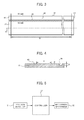
- FIG. 3 is an explanatory drawing showing a separating plate seen from a direction along a arrow in FIG. 2 together with the fixing roller.
- FIG. 4 is a sectional view showing the separating plate seen from a direction seen from a IV-IV arrow in FIG. 3 .
- FIG. 5 is a schematic block diagram showing a configuration concerning control in the fixing device according to the first embodiment of the present disclosure.
- FIG. 6A and FIG. 6B are explanatory drawings showing an operation of a nip forming mechanism in the fixing device according to the first embodiment of the present disclosure.
- FIG. 7 is an explanatory drawing showing a configuration and an operation for detecting a bending or leaping up of the sheet in the fixing device according to the first embodiment of the present disclosure.
- FIG. 8 is a schematic block diagram showing a configuration concerning control in the fixing device according to a second embodiment of the present disclosure.
- FIG. 9 is a sectional view showing a variation example of the separating plate in the fixing device according to the first or second embodiment of the present disclosure.
- FIG. 10 is a sectional view showing another variation example of the separating plate in the fixing device according to the first or second embodiment of the present disclosure.
- FIG. 11 is an explanatory drawing showing another configuration and an operation for detecting a bending or leaping up of the sheet in the fixing device according to the first or second embodiment of the present disclosure.
- FIG. 1 shows an image forming apparatus according to a first embodiment of the present disclosure.
- an image forming apparatus 1 according to the first embodiment of the present disclosure is an electrographic image forming apparatus, for example, a color printer.
- a sheet feeding cartridge 3 configured to accommodate sheets that serve as recording mediums is installed, and an upper part of the housing 2 , a sheet ejecting tray 4 in which the printed sheets are ejected is provided.
- an intermediate transferring belt 7 is looped over a drive roller 5 and a co-rotation roller 6 , four image forming parts 8 corresponding to respective four colors such as magenta, cyan, yellow and black are provided so as to be along the intermediate transferring belt 7 .
- each of the image forming parts 8 includes a photosensitive drum 9 , a charger 10 , a development device 11 , a primary transfer roller 12 , a cleaning device 13 , and a static eliminator 14 .
- an exposure device 15 constructed by a laser scanning unit is provided in the housing 2 .
- four toner containers 16 respectively corresponding to the above-mentioned four colors are provided.
- a conveying path 21 configured to convey the sheets from a side at which the sheet feeding cartridge 3 is placed to a side at which the sheet ejecting tray 4 is placed.
- a sheet feeding roller 22 is provided in the vicinity of the sheet feeding cartridge 3 , and a secondary transfer roller 23 that faces the drive roller 5 is provided at a downstream side of the sheet feeding roller 22 .
- a fixing device 25 is provided at a downstream side of the secondary transfer roller 23 , and an ejecting roller 26 is provided at a downstream side of the fixing device 25 .
- a controller 27 (see FIG. 5 ) that controls respective devices provided in the image forming apparatus 1 including the fixing device 25 is provided.
- the controller 27 has a processor controller and a storage device and the like.
- Printing operation of the image forming apparatus 1 having such a configuration is as follows.
- the drive roller 5 and the co-rotation roller 6 rotate, and the intermediate transferring belt 7 rotates.
- image forming treatment of one color of the above-mentioned four colors is carried out.
- the surface of the photosensitive drum 9 is charged by the charger 10 , laser light L corresponding to the image data is radiated from the exposure device 15 to the photosensitive drum 9 , an electrostatic latent image is formed on the surface of the photosensitive drum 9 , further, a toner image corresponding to the electrostatic latent image is formed on the surface of the photosensitive drum 9 by a development device 11 . Then, the toner image formed on the surface of the photosensitive drum 9 is transferred to the surface of the intermediate transferring belt 7 by the primary transfer roller 12 .
- the toner remaining on the surface of the photosensitive drum 9 is removed and collected by the cleaning device 13 , and an electric charge on the surface of the photosensitive drum 9 is removed by the static eliminator 14 .
- image forming treatments of the remaining three colors similar to the above-mentioned image forming treatment are sequentially carried out in other three image forming parts 8 .
- the toner images formed on the surface of the photosensitive drum 9 are transferred on the surface of the intermediate transferring belt 7 such that the respective toner images overlap with each other. As a result, a toner image of color image is formed on the surface of the intermediate transferring belt 7 .
- the sheets accommodated in the sheet feeding cartridge 3 is conveyed by the sheet feeding roller 22 and the like and pass between the intermediate transferring belt 7 around the drive roller 5 and the secondary transfer roller 23 .
- the toner image formed on the surface of the intermediate transferring belt 7 is transferred on the surface of the sheet.
- the sheet having a transferred toner image passes between the fixing roller 31 and the pressing roller 32 of the fixing device 25 .
- the toner image is melted due to heat of the fixing roller 31 heated by a halogen heater 33 to be fixed to the sheet.
- the sheet having a fixed toner image is conveyed by the ejecting roller 26 and the like, and is ejected to the sheet ejecting tray 4 .
- FIG. 2 shows the fixing device 25 according to an embodiment of the present disclosure.
- FIG. 3 shows a separating plate 41 seen from a direction along an arrow in FIG. 2 together with the fixing roller 31
- FIG. 4 shows a sectional plane of the separating plate 41 seen from a direction along an arrow IV-IV in FIG. 3
- FIG. 5 shows a configuration concerning control in the fixing device 25 .
- the fixing device 25 is provided on the way of the conveying path 21 of the sheet, and is a device configured to fix the toner image formed on the sheet to the sheet.
- the fixing device 25 includes the fixing roller 31 that serves as a fixing member, the pressing roller 32 that serves as a pressing member, the halogen heater 33 that serves as a heat source and a nip forming mechanism 35 .
- the fixing roller 31 is formed in a cylindrical shape elongated in an axis direction thereof, and is rotatably supported around an axis X 1 by a frame (not shown) that forms a contour of the fixing device 25 .
- the length of the fixing roller 31 in the axis direction is set to be longer than a width of the sheet having a maximum size usable in the image forming apparatus 1 (length of the sheet in a direction orthogonally crossing the conveyance direction of the sheet).
- the fixing roller 31 is formed by, for example, laminating PFA (tetrafluoroethylene perfluoromethylalkylvinyl ether copolymer) on the circumference face of a cored bar made of aluminum.
- the pressing roller 32 is formed in a cylindrical shape elongated in an axis direction thereof, and is rotatably supported around an axis X 2 parallel to the axis X 1 by the frame of the fixing device 25 .
- the length of the pressing roller 32 in the axis direction is identical to the length of the fixing roller 31 in the axis direction.
- the pressing roller 32 is formed by laminating a silicone rubber layer on the cored bar made of aluminum and covering with a PFA tube.
- the pressing roller 32 is rotated by a drive mechanism (not shown) including a motor and a power transmission mechanism or the like.
- the halogen heater 33 is provided in an inner part of the cored bar of the fixing roller 31 .
- the halogen heater 33 heats the entire region through which the sheet passes in the fixing roller 31 .
- the nip forming mechanism 35 is a mechanism configured to press the fixing roller 31 and the pressing roller 32 one another to form a nip part 34 between the fixing roller 31 and the pressing roller 32 .
- the nip forming mechanism 35 changes an amount of the force for pressing the fixing roller 31 and the pressing roller 32 one another, thereby changing a pressure applied to the sheet that passes through the nip part 34 (i.e. nip pressure).
- the nip forming mechanism 35 includes a pair of biasing parts 36 (Only one of the pair is shown) and a cam 37 .
- the pair of the biasing parts 36 respectively press both end parts of the axis part 32 A of the pressing roller 32 toward a direction that the axis part 32 A of the pressing roller 32 comes close to the fixing roller 31 .
- the cam 37 change pressing force of each of the biasing parts 36 that press the pressing roller 32 by changing the position thereof in the rotation direction.
- FIG. 6A and FIG. 6B show an operation that the nip forming mechanism 35 changes the amount of force for pressing the fixing roller 31 and the pressing roller 32 .
- FIG. 6A when the cam 37 is rotated to set the position thereof to a first predetermined position, force that the cam 37 presses each of the biasing parts 36 increases, the force that each of the biasing parts 36 presses the pressing roller 32 increases, thereby causing an increase in the force for pressing the fixing roller 31 and the pressing roller 32 one another.
- the degree that a part of the circumference face of the pressing roller 32 is pressed by the fixing roller 31 and is subject to elastic deformation in a recessed shape becomes large.
- the radius of the fixing roller 31 is denoted as “r”
- an angle of a fan-shaped part that forms the nip part 34 in the fixing roller 31 is denoted as “ ⁇ ”
- the length of the nip part 34 is denoted as “2 ⁇ r ⁇ /360”.
- an angle of the fan-shaped part that forms the nip part 34 in the fixing roller 31 is “ ⁇ ” that is smaller than “ ⁇ ”, and the length of the nip part 34 is “2 ⁇ r ⁇ /360”.
- the fixing device 25 is provided with an upstream side guide plate 38 placed at an upstream side of the nip part 34 in the conveying path 21 of the sheet (see FIG. 1 ) and configured to guide the sheet that moves into the fixing device 25 to the nip part 34 , a downstream side guide plate 39 placed at a downstream side of the nip part 34 in the conveying path 21 of the sheet and configured to guide the sheet that is ejected from the nip part 34 to the downstream side of the conveying path 21 , and the ejecting roller 26 placed at a downstream side of the nip part 34 in the conveying path 21 of the sheet and configured to convey the sheet that is ejected from the nip part 34 to a downstream side of the conveying path 21 .
- the fixing device 25 includes a separating plate 41 .
- the separating plate 41 is placed at a downstream side of the nip part 34 in the conveying path 21 of the sheet.
- the separating plate 41 is formed in an elongate rectangular flat plate shape having long sides 42 extending in parallel with the axis X 1 of the fixing roller 31 and short sides 43 extending along the conveyance direction of the sheet.
- the length of each long side 42 of the separating plate 41 is set to be longer than a width W of a sheet having a maximum size usable in the image forming apparatus 1 .
- each short side 43 of the separating plate 41 is, for example, about 300 mm to 500 mm.
- the thickness of the separating plate 41 is, for example, about 100 ⁇ m to 500 ⁇ m.
- the separating plate 41 is formed by, for example, coating the surface of the stainless plate with a fluorine resin.
- an edge part of the long side 42 facing the nip part 34 is extremely close to the circumference face of the fixing roller 31 but is not contact with the circumference face of the fixing roller 31 , and is apart from the circumference face of the fixing roller 31 by a predetermined distance.
- the separating plate 41 has a receiving surface 45 . Specifically, as shown in FIG. 2 , of surfaces of the separating plate 41 , a flat surface facing the conveying path 21 of the sheet is the receiving surface 45 .
- the separating plate 41 has a function of separating the sheet from the fixing roller 31 by making the front end side of the sheet that is ejected from the nip part 34 come into contact with the receiving surface 45 and make the sheet be oriented to the conveying path 21 at the downstream side of the nip part 34 .
- a catch part 46 is formed in the receiving surface 45 of the separating plate 41 .
- the catch part 46 is a depression or groove formed in a recessed shape.
- the depth D of the catch part 46 is favorably not less than a thickness of the sheet, and in the present embodiment, is set to, for example, about 50 ⁇ m.
- the catch part 46 extends in parallel with the axis X 1 of the fixing roller 31 .
- the length of the catch part 46 is set to be longer than the width W of the sheet having a maximum size usable in the image forming apparatus 1 , and is set to be, for example, identical to the length of the long sides 42 of the separating plate 41 or slightly shorter than the length of the long sides 42 of the separating plate 41 .
- the catch part 46 is formed in a region closer to the nip part 34 than a region with which the front end side of the sheet ejected from the nip part 34 in a normal operation time of the fixing device 25 comes into contact.
- the catch part 46 as shown in FIG. 2 , is formed in an edge part at a side closer to the nip part 34 in the receiving surface 45 .
- the normal operation time of the fixing device 25 referred herein is a time during which the hardness of the pressing roller 32 does not decrease, the length of the nip part 34 is kept to a preset length, and the ejecting direction of the sheet that is ejected from the nip part 34 is a preset direction.
- the hardness of the pressing roller 32 decreases, thereby increasing in a degree of the elastic deformation in a recessed shape of the pressing roller 32 .
- the nip part 34 is elongated, and the sheet ejected from the nip part 34 sometimes excessively comes close to the fixing roller 31 .
- the normal operation time of the fixing device 25 is a time during which such a situation is not caused.
- the hardness of the pressing roller 32 does not decrease, the length of the nip part 34 is kept to a preset length, and the ejecting direction of the sheet ejected from the nip part 34 keeps a preset direction. Therefore, the time when the frequency of the printing operation in the image forming apparatus 1 is low can be considered as the normal operation time of the fixing device 25 .
- a region with which the front end side of the sheet ejected from the nip part 34 comes into contact in the normal operation time of the fixing device 25 is a region to some extent apart from the edge part of a side close to the nip part 34 in a short side direction of the separating plate 41 , for example, an intermediate region in the short side direction of the receiving surface 45 , and more specifically, is a region shown by an arrow S in FIG. 4 .
- a region with which the front end side of the sheet ejected from the nip part 34 in the normal operation time of the fixing device 25 can be decided by appropriately setting the force for pressing the fixing roller 31 and the pressing roller 32 one another in the normal operation time.
- the force for pressing the fixing roller 31 and the pressing roller 32 is adjusted in the normal operation time, and the front end side of the sheet ejected from the nip part 34 is allowed to come into contact with the intermediate region of the receiving surface 45 in the short side direction.
- the fixing device 25 includes a position detector 51 .
- the position detector 51 detects the condition of the sheet that is ejected from the nip part 34 .
- the position detector 51 of the present embodiment detects a leaping up at a front end side of the sheet ejected from the nip part 34 .
- the position detector 51 detects the leaping up at a front end side of the sheet ejected from the nip part 34 by radiating light toward a direction crossing the conveying path 21 of the sheet at a downstream side of the nip part 34 and detecting the position which the light reaches the front end side of the sheet ejected from the nip part 34 .
- the position detector 51 includes a radiation device configured to radiate laser light M, a light receiving device configured to receive reflection light of the laser light M.
- the position detector 51 radiates the laser light M from the radiation device, focuses the laser light M on the sheet ejected from the nip part 34 , receives the laser light M reflected onto the sheet by the light receiving device, and detects a distance between the position detector 51 and the sheet on which the laser light M is focused based on the strength of the laser light M received.
- the position detector 51 is placed in a position facing the conveying path 21 of the sheet at the downstream side of the nip part 34 .
- the position detector 51 is placed in a position apart from the receiving surface 45 by a predetermined distance.
- the predetermined distance is set to be a distance such that the sheet does not come contact with the position detector 51 even if the sheet ejected from the nip part 34 leaps up as described later.
- the position detector 51 is attached to the frame of the fixing device 25 using a bracket (not shown), for example.
- the radiation position of the light radiated from the position detector 51 is set to be a position in which the catch part 46 is formed in the receiving surface 45 , a position slightly displaced in a direction more apart from the nip part 34 from a position in which the catch part 46 is formed, or a position slightly displaced in a direction closer to the nip part 34 than a position in which the catch part 46 is formed or the like.
- the radiation position of the light is set to be a position P slightly displaced in a direction more apart from the nip part 34 than a position in which the catch part 46 is formed (a position between the region S and the catch part 46 in FIG. 4 ).
- the controller 27 controls the nip forming mechanism 35 based on a detection result of the position detector 51 , and changes the direction of the sheet ejected from the nip part 34 .
- the mechanism in which the direction of the sheet that is ejected from the nip part 34 is as follows. When force by which the fixing roller 31 and the pressing roller 32 are pressed one another decreases, the nip part 34 is shortened, the ejecting direction of the sheet that is ejected from the nip part 34 is changed in a direction apart from the circumference face of the fixing roller 31 .
- the controller 27 controls the cam 37 of the of the nip forming mechanism 35 , changes a position of the cam 37 in a rotation direction, and decreases the force for pressing the fixing roller 31 and the pressing roller 32 one another, thereby changing the direction of the front end part of the sheet that is ejected from the nip part 34 to a direction apart from the circumference face of the fixing roller 31 .
- FIG. 7 shows an operation of the fixing device 25 .
- the pressing roller 32 rotates by the drive mechanism, in accordance with the rotation of the pressing roller 32 , the fixing roller 31 that is pressed against the pressing roller 32 rotates.
- the rotation direction of the pressing roller 32 is clockwise, and the rotation direction of the fixing roller 31 is counterclockwise.
- the fixing roller 31 is heated by a halogen heater 33 .
- the sheet having a transferred toner image on a surface thereof after the secondary transfer enters the nip part 34 between the fixing roller 31 and the pressing roller 32 from a lower side of the nip part 34 in FIG. 2 or FIG. 7 .
- the surface of the sheet on which the toner image is formed comes into contact with the circumference face of the fixing roller 31 .
- the toner image on the sheet is heated by the fixing roller 31 , is pressurized by the pressing roller 32 , and is fixed on the sheet.
- the sheet is ejected upward from the nip part 34 in FIG. 2 or FIG. 7 .
- toner is mostly present in parts other than margins on the surface of the sheet, so that the toner tends to be adhered to the circumference face of the fixing roller 31 due to viscosity.
- margins are present at the front end side of the sheet and toner is absent, so that the front end side of the sheet is separated from the circumference face of the fixing roller 31 .
- the pressing roller 32 is pressed against the fixing roller 31 to deform in a recessed shape. As a result, the nip part 34 is curved.
- the front end part of the sheet that is ejected from the nip part 34 tends to come close to the circumference face of the fixing roller 31 .
- the front end side of the sheet ejected from the nip part 34 is oriented to the receiving surface 45 of the separating plate 41 .
- the front end side of the sheet ejected from the nip part 34 like a sheet E shown by solid lines in FIG. 7 , flies over the catch part 46 formed in the receiving surface 45 , passes above the catch part 46 , comes into contact with (land) the intermediate region of the receiving surface 45 in the short side direction (region S in FIG. 4 ).
- Coming of the front end side of the sheet into contact with the intermediate region of the receiving surface 45 changes the ejecting direction of the sheet such that the ejecting direction of the sheet is along the conveying path 21 .
- the sheet is guided by the downstream side guide plate 39 and the ejecting roller 26 and conveyed from the fixing device 25 to a downstream side of the conveying path 21 .
- the sheet ejected from the nip part 34 smoothly flows to the downstream side of the conveying path 21 , so that there is a low risk that the jamming is generated inside the fixing device 25 .
- the fixing device 25 when the fixing device 25 is not in a normal operation, in the receiving surface 45 of the separating plate 41 , the position with which the front end side of the sheet ejected from the nip part 34 comes into contact is displaced in a direction close to the nip part 34 .
- the hardness of the pressing roller 32 decreases. Thereby, the degree that the pressing roller 32 is subject to elastic deformation in a recessed shape increases. As a result, the nip part 34 becomes longer.
- the ejecting direction of the sheet that is ejected from the nip part 34 comes close to the circumference face of the fixing roller 31 .
- the position with which the front end side of the sheet comes into contact is gradually displaced to a direction close to the nip part 34 .
- the current stage is an initial stage at which a risk of generation of the jamming is caused, and is not a stage immediately before the jamming is generated.
- the front end side of the sheet becomes unable to fly over the catch part 46 formed in the receiving surface 45 with time.
- the front end part of the sheet enters the catch part 46 .
- the sheet is pressed toward the ejecting direction by the fixing roller 31 and the pressing roller 32 in the state where the front end part of the sheet enters the catch part 46 , so that the front end side of the sheet is largely bent and is protruded toward a direction apart from the receiving surface 45 .
- the front end part of the sheet After the front end part of the sheet enters the catch part 46 , the front end part of the sheet gets out of the catch part 46 , due to elastic force of the bent sheet, as a sheet G shown by a two-dot chain line in FIG. 7 . At this time, the front end side of the sheet largely leaps up (floats up) toward a direction apart from the receiving surface 45 .
- the position detector 51 detects the position of the front end side of the sheet ejected from the nip part 34 . Specifically, the position detector 51 radiates the laser light M toward a position slightly displaced more apart from the nip part 34 than a position where the catch part 46 is formed in the receiving surface 45 of the separating plate 41 (concretely, a position P in FIG. 4 ). In the normal operation time of the fixing device 25 , like a sheet E shown by a solid line in FIG. 7 , when the sheet ejected from the nip part 34 smoothly flows toward the downstream side of the conveying path 21 , the laser light M is focused on the front end side of the sheet in a position H 1 .
- the fixing device 25 when the front end side of the sheet ejected from the nip part 34 leaps up by entering and getting out of the catch part 46 , the laser light M is focused on the front end side of the sheet in a position H 2 .
- the position H 2 is more apart from the receiving surface 45 than the position H 1 , and close to the position detector 51 .
- the position detector 51 detects a distance between the position detector 51 and the position where the laser light M is focused on the front end side of the sheet, and outputs a detection signal that shows the detection result to the controller 27 .
- the controller 27 receives the detection signal outputted from the position detector 51 and recognizes the presence/absence of the leaping up of the front end side of the sheet that is ejected from the nip part 34 based on the detection signal, and determines whether or not the degree that the ejecting direction of the sheet that is ejected from the nip part 34 comes close to the circumference face of the fixing roller 31 increases, based on the presence/absence of the leaping up. In addition, when the controller 27 determines that the degree that the ejecting direction of the sheet ejected from the nip part 34 comes close to the circumference face of the fixing roller 31 increases, the controller 27 controls the nip forming mechanism 35 , as shown in FIG.
- the controller 27 determines that the degree that the ejecting direction of the sheet ejected from the nip part 34 comes close to the circumference face of the fixing roller 31 does not increase based on the detection signal outputted from the position detector 51 , the controller 27 maintains the present condition of the nip forming mechanism 35 , and maintains the direction of the front end part of the sheet that is ejected from the nip part 34 as it is.
- the catch part 46 is formed in the receiving surface 45 of the separating plate 41 , and when the degree that the ejecting direction of the sheet ejected from the nip part 34 comes close to the circumference face of the fixing roller 31 increases, the catch part 46 catches the front end part of the sheet, and then releases the front end part of the sheet therefrom, and makes the front end side of the sheet leap up, thereby largely changing the condition of the sheet that ejected from the nip part 34 . Then, the position detector 51 detects the large change of the condition of the sheet emphasized in such a manner. Accordingly, an increase of the degree that the ejecting direction of the sheet ejected from the nip part 34 comes close to the circumference face of the fixing roller 31 can be clearly recognized, which enables a sure avoiding generation of the jamming.
- the fixing device 25 a risk of generation of the jamming can be recognized in an early stage.
- the fixing device 25 can recognize the risk of the generation of the jamming not immediately before the generation of the jamming, but an earlier stage. Therefore, the generation of the jamming can be surely inhibited.
- the catch part 46 is formed in an edge part at a side close to the nip part 34 in the receiving surface 45 of the separating plate 41 . Therefore, the sheet ejected from the nip part 34 in the normal operation time surely flies over the catch part 46 . In other words, an error that the catch part 46 catches the sheet despite in the normal operation time can be prevented. Namely, only when the degree that the ejecting direction of the sheet ejected from the nip part 34 comes close to the circumference face of the fixing roller 31 increases, the sheet can be caught by the catch part 46 . According to this, the increase of the degree that the ejecting direction of the sheet ejected from the nip part 34 comes close to the circumference face of the fixing roller 31 can be recognized with high accuracy, which enables prevention of erroneous recognition.
- the length of the catch part 46 is set to be longer than the width W of the sheet having a maximum size usable in the image forming apparatus 1 , so that the front end part of the sheet ejected from the nip part 34 can be surely caught. That makes it possible for the amount of the bending or leaping up of the sheet in catching or releasing to be large and for the position detector 51 to more clearly detect the bending or leaping up of the sheet.
- the position detector 51 radiates light along a direction crossing the conveying path 21 of the sheet at the downstream side of the nip part 34 and detects a position where the light reaches the front end side of the sheet ejected from the nip part 34 , thereby detecting the leaping up of the front end side of the sheet ejected from the nip part 34 . That makes it possible for the position detector 51 to easily detect the bending or leaping up of the sheet when the catch part 46 catches or releases the sheet.
- the position of the front end side of the sheet ejected from the nip part 34 is detected by using the laser light M reflected at the front end side of the sheet, thereby enabling detection with high accuracy of the leaping up of the sheet getting out of the catch part 46 with a compact configuration.
- the nip forming mechanism 35 is controlled and the force for pressing the fixing roller 31 and the pressing roller 32 one another is decreased, thereby enabling sure separating the ejecting direction of the sheet ejected from the nip part 34 from the fixing roller 31 .
- FIG. 8 shows a configuration concerning control in a fixing device according to a second embodiment of the present disclosure.
- the position detector 51 and a halogen heater 33 are connected to a controller 61 of the fixing device or an image forming apparatus including the fixing device according to the second embodiment of the present disclosure.
- the controller 61 controls the halogen heater 33 and changes the direction of the sheet that is ejected from the nip part 34 based on a detection result of the position detector 51 .
- the mechanism of changing the direction of the sheet that is ejected from the nip part 34 is as follows.
- the front end part of the sheet ejected from the nip part 34 is curved in a direction coming close to the fixing roller 31 .
- the degree of the curvature is large as the fixing temperature increases and is small as the fixing temperature decreases. Therefore, the controller 61 controls the halogen heater 33 to decrease the fixing temperature, thereby enabling a decrease in the degree of the curvature of the sheet. That enables a change of the direction of the front end part of the sheet ejected from the nip part 34 to a direction apart from the circumference face of the fixing roller 31 .
- the fixing device according to the second embodiment has a configuration similar to the fixing device 25 according to the first embodiment except that a means for decreasing the fixing temperature is employed instead of a means for decreasing force for pressing the fixing roller 31 and the pressing roller 32 as a means for changing the ejecting direction of the sheet that is ejected from the nip part 34 .
- the catch part 46 of the separating plate 41 is formed in a recessed shape.
- a catch part 48 of a separating plate 47 may be formed in a projected shape, or as shown in FIG. 10 , a catch part 50 of a separating plate 49 may be formed in a stepwise shape (or formed as a difference in thickness in the edge portion).
- the radiation position of the laser light M radiated from the position detector 51 is set to be the position P slightly displaced in a direction more apart from the nip part 34 than a position in which the catch part 46 is formed in the receiving surface 45 of the separating plate 41 is exemplified.
- the irradiation position of the laser light M may be set to be a position slightly displaced in a direction coming closer to the nip part 34 than a position where the catch part 46 is formed in the receiving surface 45 .
- the position where the laser light M is focused on the sheet E that flies over the catch part 46 and smoothly flows is a position H 3 .
- the position where the laser light M is focused on the sheet F that is caught by the catch part 46 and is largely bent to be protruded from the receiving surface 45 is a position H 4 .
- the position detector 51 detects a distance between the position detector 51 and the position where the laser light M is focused on the sheet, thereby detecting a large bending of the front end side of the sheet ejected from the nip part 34 .
- the controller 27 recognizes presence/absence of the bending of the front end side of the sheet ejected from the nip part 34 based on the detection result, and determines if the degree that the ejecting direction of the sheet ejected from the nip part 34 comes close to the circumference face of the fixing roller 31 increases or not.
- a radiation part and a light receiving part of the position detector 51 may be respectively placed at both end sides in the axis direction of the place where the sheet is ejected from the nip part 34 , and the laser light M may be radiated along the axis direction, whereby the leaping up or bending of the sheet that is ejected from the nip part 34 may be detected.
- the laser light M radiated from the radiation part to the light receiving part is configured to be blocked by the sheet.
- the position detector 51 may continuously detect the leaping up or bending of the sheet ejected from the nip part 34 , and the force for pressing the fixing roller 31 and the pressing roller 32 or the fixing temperature may be increased/decreased in a multi-stage or continuous manner based on the frequency of the leaping up or bending or the like.
- the fixing device of the present disclosure can be applied to a case where the fixing roller 31 is pressed by the pressing roller 32 to deform, or a case where both of the fixing roller 31 and the pressing roller 32 press each other to deform.
- the heat source is not limited to the halogen heater, and for example IH (induction heating) heater may be used.
- the fixing device of the present disclosure is not limited to a roller-type fixing device using a fixing roller, and a belt-type fixing device using a fixing belt may be used.
- the fixing device of the present disclosure can be also applied not only an image forming apparatus for carrying out a color printing, but also an image forming apparatus for carrying out a black-and-white printing.
- the fixing device of the present disclosure is not limited to a printer, and can be applied to a copying machine, a facsimile or a multifunction peripheral.
Landscapes
- Physics & Mathematics (AREA)
- General Physics & Mathematics (AREA)
- Fixing For Electrophotography (AREA)
Abstract
Description
Claims (7)
Applications Claiming Priority (2)
| Application Number | Priority Date | Filing Date | Title |
|---|---|---|---|
| JP2015020140A JP6233325B2 (en) | 2015-02-04 | 2015-02-04 | Fixing apparatus and image forming apparatus |
| JP2015-020140 | 2015-02-04 |
Publications (2)
| Publication Number | Publication Date |
|---|---|
| US20160223970A1 US20160223970A1 (en) | 2016-08-04 |
| US9442444B2 true US9442444B2 (en) | 2016-09-13 |
Family
ID=56554156
Family Applications (1)
| Application Number | Title | Priority Date | Filing Date |
|---|---|---|---|
| US15/014,067 Expired - Fee Related US9442444B2 (en) | 2015-02-04 | 2016-02-03 | Fixing device and image forming apparatus |
Country Status (3)
| Country | Link |
|---|---|
| US (1) | US9442444B2 (en) |
| JP (1) | JP6233325B2 (en) |
| CN (1) | CN105843020B (en) |
Families Citing this family (1)
| Publication number | Priority date | Publication date | Assignee | Title |
|---|---|---|---|---|
| JP7091633B2 (en) * | 2017-11-02 | 2022-06-28 | 京セラドキュメントソリューションズ株式会社 | Image forming device |
Citations (6)
| Publication number | Priority date | Publication date | Assignee | Title |
|---|---|---|---|---|
| US5017970A (en) * | 1987-06-30 | 1991-05-21 | Minolta Camera Kabushiki Kaisha | Fixing device with movable nip region for use in copiers |
| JP2010256926A (en) | 2010-06-28 | 2010-11-11 | Ricoh Co Ltd | Recording body abnormality occurrence prediction apparatus and image forming apparatus |
| US20120224893A1 (en) * | 2011-03-01 | 2012-09-06 | Takeshi Yamamoto | Media stripper mechanism, fixing device, and image forming apparatus |
| US9069298B2 (en) * | 2012-08-16 | 2015-06-30 | Ricoh Company, Ltd. | Separation device, fixing device, and image forming apparatus |
| US20150309455A1 (en) * | 2014-04-25 | 2015-10-29 | Oki Data Corporation | Fixing device and image forming apparatus |
| US20160026140A1 (en) * | 2014-07-28 | 2016-01-28 | Konica Minolta Inc. | Sheet conveying device and image forming apparatus |
Family Cites Families (12)
| Publication number | Priority date | Publication date | Assignee | Title |
|---|---|---|---|---|
| JPH08171302A (en) * | 1994-12-15 | 1996-07-02 | Canon Inc | Fixing device for image forming apparatus |
| JP2004077893A (en) * | 2002-08-20 | 2004-03-11 | Canon Inc | Image forming device |
| JP2006011174A (en) * | 2004-06-28 | 2006-01-12 | Ricoh Co Ltd | Recorder abnormality occurrence prediction device, fixing device, and image forming apparatus |
| JP4264410B2 (en) * | 2004-11-30 | 2009-05-20 | 株式会社リコー | Fixing apparatus and image forming apparatus |
| JP4846344B2 (en) * | 2005-09-16 | 2011-12-28 | 株式会社リコー | Image forming apparatus |
| US7310491B2 (en) * | 2005-09-23 | 2007-12-18 | Xerox Corporation | Non-gouging sheet stripper assembly |
| KR100782832B1 (en) * | 2006-01-17 | 2007-12-06 | 삼성전자주식회사 | Discharge system of image forming apparatus and discharge method using same |
| CN100585513C (en) * | 2006-08-30 | 2010-01-27 | 京瓷美达株式会社 | Fixing device, image forming device, sheet conveying device |
| JP5581634B2 (en) * | 2009-09-15 | 2014-09-03 | 株式会社リコー | Fixing apparatus and image forming apparatus |
| CN102213938A (en) * | 2010-04-05 | 2011-10-12 | 株式会社东芝 | Image forming apparatus and method of adjusting gap |
| JP5998706B2 (en) * | 2012-07-26 | 2016-09-28 | カシオ電子工業株式会社 | Fixing apparatus and image forming apparatus |
| JP6121249B2 (en) * | 2013-06-05 | 2017-04-26 | シャープ株式会社 | Fixing apparatus and image forming apparatus |
-
2015
- 2015-02-04 JP JP2015020140A patent/JP6233325B2/en not_active Expired - Fee Related
-
2016
- 2016-01-26 CN CN201610053249.8A patent/CN105843020B/en not_active Expired - Fee Related
- 2016-02-03 US US15/014,067 patent/US9442444B2/en not_active Expired - Fee Related
Patent Citations (6)
| Publication number | Priority date | Publication date | Assignee | Title |
|---|---|---|---|---|
| US5017970A (en) * | 1987-06-30 | 1991-05-21 | Minolta Camera Kabushiki Kaisha | Fixing device with movable nip region for use in copiers |
| JP2010256926A (en) | 2010-06-28 | 2010-11-11 | Ricoh Co Ltd | Recording body abnormality occurrence prediction apparatus and image forming apparatus |
| US20120224893A1 (en) * | 2011-03-01 | 2012-09-06 | Takeshi Yamamoto | Media stripper mechanism, fixing device, and image forming apparatus |
| US9069298B2 (en) * | 2012-08-16 | 2015-06-30 | Ricoh Company, Ltd. | Separation device, fixing device, and image forming apparatus |
| US20150309455A1 (en) * | 2014-04-25 | 2015-10-29 | Oki Data Corporation | Fixing device and image forming apparatus |
| US20160026140A1 (en) * | 2014-07-28 | 2016-01-28 | Konica Minolta Inc. | Sheet conveying device and image forming apparatus |
Also Published As
| Publication number | Publication date |
|---|---|
| CN105843020A (en) | 2016-08-10 |
| JP6233325B2 (en) | 2017-11-22 |
| CN105843020B (en) | 2018-05-22 |
| JP2016142977A (en) | 2016-08-08 |
| US20160223970A1 (en) | 2016-08-04 |
Similar Documents
| Publication | Publication Date | Title |
|---|---|---|
| US9268276B2 (en) | Fixing device and image forming apparatus that include a separator disposed downstream from a fixing nip | |
| US9046834B2 (en) | Fixing device and image forming apparatus | |
| US20100189447A1 (en) | Image forming apparatus | |
| US9645534B2 (en) | Contactless type temperature detecting device configured to detect a temperature of a heated body without contacting, and fixing device and image forming apparatus including the temperature device | |
| US20120039644A1 (en) | Sheet conveying apparatus | |
| US20160139550A1 (en) | Image forming apparatus and recording material determination unit | |
| US20180017901A1 (en) | Medium transport apparatus and image forming apparatus | |
| US9335691B2 (en) | Fixing device and image forming apparatus | |
| US9442444B2 (en) | Fixing device and image forming apparatus | |
| JP2014191302A (en) | Fixing device | |
| US8910938B2 (en) | Medium carrying device and image forming apparatus | |
| US9817344B2 (en) | Fixing device capable of sensing temperature of heating body outside frame surrounding heating body regardless of moving frame and image forming apparatus including this fixing device | |
| US20160054690A1 (en) | Fixing device and image forming apparatus having moving member to block radiant heat and moving by a friction force between a fixing belt and the moving member. | |
| US9436141B2 (en) | Fixing device comprising controller which judges whether or not fixing belt is rotating and image forming apparatus including same | |
| JP7119281B2 (en) | Fixing device and image forming device | |
| US9405246B2 (en) | Fixing device comprising heating stop device to stop heat source from heating fixing belt and image forming apparatus including same | |
| JP2010052887A (en) | Paper conveyance device and image forming device | |
| US10185272B2 (en) | Image forming apparatus | |
| US9405245B2 (en) | Fixing device comprising deformation preventing member for preventing deformation of fixing belt and image forming apparatus including same | |
| JP7771670B2 (en) | Image forming device | |
| US9658583B2 (en) | Fixing device and image forming apparatus | |
| JP2020071346A (en) | Thermal fixing device and image forming device | |
| US9372457B2 (en) | Fixing device and image forming apparatus | |
| JP5650829B2 (en) | Image forming apparatus and fixing unit | |
| JP6337575B2 (en) | Fixing apparatus and image forming apparatus |
Legal Events
| Date | Code | Title | Description |
|---|---|---|---|
| AS | Assignment |
Owner name: KYOCERA DOCUMENT SOLUTIONS INC., JAPAN Free format text: ASSIGNMENT OF ASSIGNORS INTEREST;ASSIGNOR:HAMADA, TOSHIYUKI;REEL/FRAME:037651/0557 Effective date: 20160115 |
|
| ZAAA | Notice of allowance and fees due |
Free format text: ORIGINAL CODE: NOA |
|
| ZAAB | Notice of allowance mailed |
Free format text: ORIGINAL CODE: MN/=. |
|
| STCF | Information on status: patent grant |
Free format text: PATENTED CASE |
|
| MAFP | Maintenance fee payment |
Free format text: PAYMENT OF MAINTENANCE FEE, 4TH YEAR, LARGE ENTITY (ORIGINAL EVENT CODE: M1551); ENTITY STATUS OF PATENT OWNER: LARGE ENTITY Year of fee payment: 4 |
|
| FEPP | Fee payment procedure |
Free format text: MAINTENANCE FEE REMINDER MAILED (ORIGINAL EVENT CODE: REM.); ENTITY STATUS OF PATENT OWNER: LARGE ENTITY |
|
| LAPS | Lapse for failure to pay maintenance fees |
Free format text: PATENT EXPIRED FOR FAILURE TO PAY MAINTENANCE FEES (ORIGINAL EVENT CODE: EXP.); ENTITY STATUS OF PATENT OWNER: LARGE ENTITY |
|
| STCH | Information on status: patent discontinuation |
Free format text: PATENT EXPIRED DUE TO NONPAYMENT OF MAINTENANCE FEES UNDER 37 CFR 1.362 |
|
| FP | Lapsed due to failure to pay maintenance fee |
Effective date: 20240913 |