US9438318B2 - Extracting sub-bands from signals in a frequency domain - Google Patents
Extracting sub-bands from signals in a frequency domain Download PDFInfo
- Publication number
- US9438318B2 US9438318B2 US14/255,739 US201414255739A US9438318B2 US 9438318 B2 US9438318 B2 US 9438318B2 US 201414255739 A US201414255739 A US 201414255739A US 9438318 B2 US9438318 B2 US 9438318B2
- Authority
- US
- United States
- Prior art keywords
- sub
- downlink signal
- band
- unit
- transformed
- Prior art date
- Legal status (The legal status is an assumption and is not a legal conclusion. Google has not performed a legal analysis and makes no representation as to the accuracy of the status listed.)
- Active
Links
- 230000005540 biological transmission Effects 0.000 claims abstract description 21
- 238000012545 processing Methods 0.000 claims description 31
- 238000000034 method Methods 0.000 claims description 19
- 238000005070 sampling Methods 0.000 claims description 19
- 239000000284 extract Substances 0.000 claims description 14
- CKLJMWTZIZZHCS-UWTATZPHSA-N D-aspartic acid Chemical compound OC(=O)[C@H](N)CC(O)=O CKLJMWTZIZZHCS-UWTATZPHSA-N 0.000 description 25
- 238000004891 communication Methods 0.000 description 12
- 238000010295 mobile communication Methods 0.000 description 9
- 238000001228 spectrum Methods 0.000 description 9
- 238000010586 diagram Methods 0.000 description 8
- 238000001914 filtration Methods 0.000 description 7
- 230000001131 transforming effect Effects 0.000 description 5
- 238000006243 chemical reaction Methods 0.000 description 4
- 239000002131 composite material Substances 0.000 description 3
- 239000002609 medium Substances 0.000 description 3
- 230000002238 attenuated effect Effects 0.000 description 2
- 125000004122 cyclic group Chemical group 0.000 description 2
- 238000005259 measurement Methods 0.000 description 2
- 230000003595 spectral effect Effects 0.000 description 2
- RYGMFSIKBFXOCR-UHFFFAOYSA-N Copper Chemical compound [Cu] RYGMFSIKBFXOCR-UHFFFAOYSA-N 0.000 description 1
- 230000006978 adaptation Effects 0.000 description 1
- 230000003750 conditioning effect Effects 0.000 description 1
- 229910052802 copper Inorganic materials 0.000 description 1
- 239000010949 copper Substances 0.000 description 1
- 230000001934 delay Effects 0.000 description 1
- 238000005516 engineering process Methods 0.000 description 1
- 230000007774 longterm Effects 0.000 description 1
- 238000012986 modification Methods 0.000 description 1
- 230000004048 modification Effects 0.000 description 1
- 239000013307 optical fiber Substances 0.000 description 1
- 238000012552 review Methods 0.000 description 1
- 238000000926 separation method Methods 0.000 description 1
- 239000006163 transport media Substances 0.000 description 1
Images


Classifications
-
- H—ELECTRICITY
- H04—ELECTRIC COMMUNICATION TECHNIQUE
- H04L—TRANSMISSION OF DIGITAL INFORMATION, e.g. TELEGRAPHIC COMMUNICATION
- H04L27/00—Modulated-carrier systems
- H04L27/26—Systems using multi-frequency codes
- H04L27/2601—Multicarrier modulation systems
- H04L27/2626—Arrangements specific to the transmitter only
- H04L27/2627—Modulators
-
- H—ELECTRICITY
- H04—ELECTRIC COMMUNICATION TECHNIQUE
- H04B—TRANSMISSION
- H04B1/00—Details of transmission systems, not covered by a single one of groups H04B3/00 - H04B13/00; Details of transmission systems not characterised by the medium used for transmission
- H04B1/38—Transceivers, i.e. devices in which transmitter and receiver form a structural unit and in which at least one part is used for functions of transmitting and receiving
- H04B1/40—Circuits
-
- H—ELECTRICITY
- H04—ELECTRIC COMMUNICATION TECHNIQUE
- H04B—TRANSMISSION
- H04B7/00—Radio transmission systems, i.e. using radiation field
- H04B7/02—Diversity systems; Multi-antenna system, i.e. transmission or reception using multiple antennas
- H04B7/022—Site diversity; Macro-diversity
- H04B7/026—Co-operative diversity, e.g. using fixed or mobile stations as relays
-
- H—ELECTRICITY
- H04—ELECTRIC COMMUNICATION TECHNIQUE
- H04L—TRANSMISSION OF DIGITAL INFORMATION, e.g. TELEGRAPHIC COMMUNICATION
- H04L5/00—Arrangements affording multiple use of the transmission path
- H04L5/0001—Arrangements for dividing the transmission path
- H04L5/0003—Two-dimensional division
- H04L5/0005—Time-frequency
-
- H—ELECTRICITY
- H04—ELECTRIC COMMUNICATION TECHNIQUE
- H04W—WIRELESS COMMUNICATION NETWORKS
- H04W72/00—Local resource management
- H04W72/20—Control channels or signalling for resource management
- H04W72/27—Control channels or signalling for resource management between access points
Definitions
- the present disclosure relates generally to telecommunications systems and more particularly (although not necessarily exclusively) to extracting sub-bands of interest from signals in a frequency domain.
- a distributed antenna system can provide a signal transport network for communicating signals between one or more base stations and mobile communication devices or other terminal devices.
- the DAS may include master units and remote antenna units.
- the master units may be connected to the base stations.
- the master units receive downlink signals from the base stations and distribute downlink signals in analog or digital format to multiple remote antenna units.
- the remote antenna units transmit downlink signals to mobile communication devices or other terminal devices within coverage areas serviced by the remote antenna units.
- the remote antenna units receive uplink signals from terminal devices in the serviced coverage areas.
- the remote antenna units may combine uplink signals and transmit the combined uplink signals to master units.
- the master units may transmit uplink signals to the serving base stations.
- a signal transport network provided by a DAS may be implemented using analog systems or digital systems.
- a digital system can include one or more devices for digitizing analog downlink signals received from a base station.
- a digital representation of the analog waveform is used to transmit the downlink signal via the DAS.
- a master unit may route an entire downlink signal to remote antenna units of the DAS. Routing an entire downlink signal to remote antenna units can involve unnecessarily routing frequency bands in which no voice data or other data is transmitted.
- Certain aspects and features of the present invention are directed to distributed antenna systems that can extract sub-bands of interest from signals in a frequency domain.
- a method for extracting sub-bands of interest from signals in a frequency domain for transmission via a distributed antenna system involves generating a transformed downlink signal by performing a frequency transform on a downlink signal.
- the transformed downlink signal represents the downlink signal in a frequency domain.
- the method also involves determining that at least one sub-band of the transformed downlink signal includes data to be transmitted via the distributed antenna system.
- the method involves extracting the sub-band from the transformed downlink signal for transmission via the distributed antenna system.
- a unit for extracting sub-bands of interest from signals in a frequency domain for transmission via a distributed antenna system can include a first interface section, a processor, and a second interface section.
- the first interface section can receive a downlink signal from a base station.
- the processor can generate a transformed downlink signal by performing a frequency transform on a downlink signal.
- the transformed downlink signal represents the downlink signal in a frequency domain.
- the processor can also determine that at least one sub-band of the transformed downlink signal includes data to be transmitted via the distributed antenna system.
- the processor can also extract the sub-band from the transformed downlink signal.
- the second interface section can provide the extracted sub-band to at least one remote antenna unit of the distributed antenna system.
- a distributed antenna system in another aspect, includes a unit and at least one remote antenna unit.
- the unit can receive a downlink signal and generate a transformed downlink signal by performing a frequency transform on the downlink signal.
- the transformed downlink signal represents the downlink signal in a frequency domain.
- the unit can also determine that at least one sub-band of the transformed downlink signal includes data to be transmitted via the distributed antenna system.
- the unit can also extract the at least one sub-band from the transformed downlink signal.
- the unit can also provide the extracted sub-band to the remote antenna unit.
- the remote antenna unit can generate a wireless RF signal based on the extracted sub-band and transmit the wireless RF signal to a terminal device.
- FIG. 1 is a block diagram depicting an example of a distributed antenna system in which sub-bands of interest can be extracted from signals in a frequency domain according to one aspect of the present disclosure.
- FIG. 2 is a flow chart depicting an example of a process for extracting sub-bands of interest from a downlink signal in the frequency domain according to one aspect of the present disclosure.
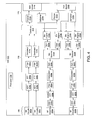
- FIG. 3 is a block diagram depicting an example of a unit of a distributed antenna system that can sub-divide downlink signals into sub-bands in the frequency domain according to one aspect of the present disclosure.
- FIG. 4 is a block diagram depicting an alternative example of a unit of a distributed antenna system that can sub-divide downlink signals into sub-bands in the frequency domain according to one aspect of the present disclosure.
- FIG. 5 is a block diagram depicting an example of a remote antenna unit of a distributed antenna system that can sub-divide uplink signals into sub-bands in the frequency domain.
- a master unit or other unit of a DAS can transform a digital downlink signal from the time domain to the frequency domain.
- the unit of the DAS can identify multiple, equally sized sub-bands from the digital downlink signal in the frequency domain.
- Dividing signals communicated via the DAS into equally spaced sub-bands can thus reduce the amount of bandwidth used to route the signals to different units of the DAS. For example, data for frequency domain representations of individual sub-bands of interest can be processed and routed to remote antenna units in the DAS. Data for frequency domain representations of other sub-bands can be discarded or otherwise omitted from routing. Processing and routing individual sub-bands of interest can obviate the need to route the entire downlink signal via the DAS.
- a unit of the DAS can include an input section, a processor, and an output section.
- the unit can receive downlink signals via the input section and output downlink signals via the output section to a remote antenna unit or other unit in the DAS.
- the processor of the unit can generate a transformed downlink signal by performing a frequency transform on the downlink signal or by configuring one or more signal processing devices to perform the frequency transform on the downlink signal.
- Performing a frequency transform on the downlink signal can include transforming the downlink signal from a time domain to a frequency domain.
- Non-limiting examples of a frequency transform can include a fast Fourier transform (“FFT”), a discrete Fourier transform, and a discrete cosine transform.
- FFT fast Fourier transform
- the processor can determine that at least one sub-band of the transformed downlink signal includes voice or other data to be transmitted via the DAS.
- the processor can extract, identify, or otherwise selected the sub-bands from the transformed downlink signal that include the voice or other data to be transmitted.
- the output section can route the sub-bands having the data to one or more remote antenna units or other units of the DAS.
- a master unit or other unit of a DAS can receive signals from base stations and convert the downlink signals into digital downlink signals.
- the master unit can decompose or otherwise sub-divide the digital downlink signals into multiple, equally sized sub-bands.
- the master unit can extract or otherwise select sub-bands of interest from the equally sized sub-bands.
- Sub-bands of interest can include sub-bands in which voice data or other data is included.
- the master unit can provide sub-bands of interest to one or more remote antenna units.
- a remote antenna unit receiving the sub-bands of interest can convert the sub-band into a composite signal for transmission to mobile communication devices in a coverage area serviced by the remote antenna unit.
- a master unit can route different sub-bands extracted from a transformed downlink signal to different sets of remote antenna units.
- Dividing signals communicated via a DAS into sub-bands can allow for separation of individual sub-bands of interest from composite signals communicated via the DAS. For example, in a time domain, a composite signal can be filtered to extract individual channels of interest, remove frequencies other than the channels of interest, or both. Transforming signals into a frequency domain representation of the signals can allow for removing the individual frequency components or otherwise manipulating the signals in a more computationally efficient manner as compared to filtering signals in the time domain. Also, each sub-band of a signal that has been divided can include digital signals sampled at the same sampling rate. Dividing signals that have been transformed into the frequency domain can provide greater computationally efficiency than extracting channels of interest using the signals in the time domain.
- the signal power for one or more sub-bands or groups of sub-bands extracted from a transformed downlink signal can be modified to increase or decrease the level of the signal in that sub-band.
- the signal level of each sub-band or a group of sub-bands can be compared to a threshold value.
- the signal level of a sub-band can be scaled up or down based on whether the signal level is above or below the threshold.
- FIG. 1 is a block diagram depicting an example of a DAS 100 in which sub-bands of interest can be extracted from signals in a frequency domain.
- the DAS 100 can communicate signals between one or more base stations 101 a , 101 b and mobile communication devices via master units and remote antenna units of the DAS 100 .
- the DAS 100 can include a unit 102 and multiple remote antenna units 112 a - c.
- the unit can be a master unit or other suitable unit that can communicate with one or more base stations 101 a , 101 b .
- the unit 102 can receive downlink signals from the base stations 101 a , 101 b and transmit uplink signals to the base stations 101 a , 101 b .
- Any suitable communication link can be used for communication between the base stations 101 a , 101 b and a unit 102 , such as (but not limited to) a wired connection or a wireless connection.
- a wired connection can include, for example, a connection via a copper cable, an optical fiber, or another suitable communication medium.
- a wireless connection can include, for example, a wireless RF communication link.
- the unit 102 can combine downlink signals received from base stations 101 a , 101 b .
- the unit 102 can transmit the combined downlink signals to one or more of the remote antenna units 112 a - c.
- the remote antenna units can provide signal coverage in respective coverage zones 114 a - c .
- Providing signal coverage in the coverage zones 114 a - c can include transmitting downlink signals received from the unit 102 to mobile communication devices or other terminal devices in the coverage zones 114 a - c .
- Providing signal coverage in the coverage zones 114 a - c can also include receiving uplink signals from the mobile communication devices or other terminal devices in the coverage zones 114 a - c .
- the remote antenna units 112 a - c can transmit the uplink signals to the unit 102 .
- the unit 102 can combine uplink signals received from remote antenna units for transmission to the base stations 101 a , 101 b.
- FIG. 1 depicts a direct connection between the unit 102 and the remote antenna units 112 a - c , other implementations are possible.
- the unit 102 can be connected to the remote antenna units 112 a - c via one or more extension units or other intermediate devices.
- the unit 102 can include a processor 104 , an interface section 106 , a signal processing section 108 , and an interface section 110 .
- the interface section 106 can include one or more physical layer (“PHY”) devices for communicating with base stations 101 a , 101 b .
- PHY physical layer
- the interface section 106 can include an external repeater, an internal RF transceiver included on an interface card, or other suitable RF interface device to communicate with the base stations 101 a , 101 b .
- the interface section 110 can include one or more PHY devices for communicating with remote antenna units or other units of a DAS 100 .
- the signal processing section 108 can include one or more modules for conditioning, filtering, combining, or otherwise processing signals received via an interface section 106 and communicated to other devices in the DAS 100 via an interface section 110 .
- the processor 104 can include any processing device or group of processing devices configured to execute one or more algorithms for identifying sub-bands of interest.
- the processor 104 can configure the signal processing section 108 to sub-divide signals into equally spaced sub-bands.
- the processor 104 can configure the signal processing section 108 to extract or otherwise select sub-bands of interest from the equally spaced sub-bands.
- the processor 104 can include any device suitable for executing program instructions stored in a non-transitory computer-readable medium or other memory device to control operation of the unit 102 . Examples of processor 104 include a microprocessor, an application-specific integrated circuit (“ASIC”), a field-programmable gate array (“FPGA”), or other suitable processor.
- ASIC application-specific integrated circuit
- FPGA field-programmable gate array
- the unit 102 can extract or otherwise identify sub-bands of interest from a downlink signal in the frequency domain.
- FIG. 2 is a flow chart depicting an example of a process for extracting sub-bands of interest from a downlink signal in the frequency domain.
- the unit 102 generates a transformed downlink signal by performing a frequency transform on a downlink signal received from a base station.
- One or both of the processor 104 and the signal processing section 108 can execute computationally efficient algorithms for generating the transformed downlink signal and for determining the equally spaced sub-bands into which downlink signals can be divided.
- an FFT can be applied to a downlink signal to convert the downlink signal from the time domain to the frequency domain.
- One or more FFT modules or modules in the signal processing section 108 of the unit can generate an FFT for a frequency spectrum used by the DAS 100 .
- Each bin of the FFT can correspond to a sub-band of the downlink signal.
- Each bin can include information about the downlink signal within the bandwidth of the bin, such as a magnitude and a phase for the sub-band in the bin.
- a length of the FFT being used can determine the bandwidth for each sub-band.
- the processor 104 can obtain a 1,024-point FFT of a signal received by the unit. The sampling rate of the digital signal can be divided into the 1,024 FFT bins.
- the processor 104 can identify sub-bands of interest within the frequency spectrum from the FFT of the frequency spectrum.
- the unit 102 can use the processor 104 to extract the identified sub-bands for processing and routing.
- the processor 104 determines that at least one sub-band of the transformed downlink signal includes data to be transmitted via the DAS 100 .
- the processor 104 can identify that the transformed downlink signal includes sub-bands of interest. For example, the processor 104 can determine that one or more bins of an FFT or other frequency transform include data having a magnitude exceeding a threshold magnitude.
- the processor 104 can analyze the downlink signal in the time domain to determine if a signal of interest is present.
- the processor 104 can calculate or otherwise determine which FFT bins include the signal of interest.
- the processor 104 can identify sub-bands of interest by examining the downlink signal in both the time and frequency domain.
- the processor 104 can detect signal characteristics consistent with mobile wireless signals. For example, the processor 104 can detect a particular modulation format and thereby identify signals of interest.
- the processor 104 can be configured by a user to extract specific spectral segments.
- the processor 104 can determine the FFT bins corresponding to the configured spectral segments.
- the processor 104 can communicate with the base station 101 a , 101 b to determine which channels are used by the base stations 101 a , 101 b .
- the processor 104 can identify the FFT bins that include the signals of interest based on which channels are used by the base stations 101 a , 101 b .
- the base stations 101 a , 101 b may transmit control signals that are addressed to the unit 102 and that identify the channels being used.
- the control signals can be transmitted via the same communication links as downlink signals that are to be communicated to terminal devices.
- the control signals can be transmitted via a dedicated communication link that is different from communication links used to transmit downlink signals to the DAS 100 .
- the unit 102 can include an interface card or other device used to communicate with one or more of the base stations 101 a , 101 b via the dedicated communication link.
- the unit 102 extracts the at least one sub-band from the transformed downlink signal.
- the processor 104 can extract or otherwise select the sub-bands of interest by selecting FFT bins corresponding to the sub-bands of interest. Each bin can represent a given amount of frequency spectrum.
- the unit 102 can transmit bins corresponding to the sub-bands of interest to one or more other remote antenna units 112 a - c .
- a portion of the downlink frequency band may lack any voice data or other data to be transmitted.
- the unit 102 can remove sub-bands from the downlink signal that correspond to the portion of the frequency band without voice or data. Removing the sub-bands can reduce the occupied bandwidth on the transport media between the unit 102 and the remote antenna units 112 a - c.
- selecting the bins of interest can cause one or more discontinuities in the frequency domain that may result in distortion in the time domain. Distortion can be minimized by filtering the sub-bands of interest from the frequency spectrum used by the DAS 100 .
- the unit 102 can select bins corresponding to the sub-bands of interest by applying a windowing function to an FFT of the frequency spectrum to minimize distortion in the time domain.
- Extracting sub-bands of interest can differ from filtering a signal in the time domain.
- Filtering signals may involve decimating the signal to reduce the sampling rate of the original signal in order to reduce the amount of bandwidth required to transport a digital version of the signal.
- a receiving device may interpolate or otherwise up-sample the received signal.
- each sub-band may be down-converted via a mixer and decimated in a low-pass filtering operation.
- To combine multiple sub-bands at an up-converter may involve tracking the phases of the down-converter and the up-converter.
- Tracking the phases of the down-converter and the up-converter can involve identifying the delays between the down-conversion process for de-composing or otherwise dividing the sub-band and the up-conversion process for reconstructing the signal at a receiving device.
- Subdividing signal in the frequency domain can obviate the need to track the phases of down-conversion and up-conversion processes.
- a phase relationship from bin to bin can be identified by the process of transforming the signal into the frequency domain.
- a filter can be applied to a signal in the time domain to sub-divide the signal into the sub-bands prior to converting the signal to the frequency domain.
- the unit 102 can include a filter bank or a set of discrete filters in the signal processing section 108 prior to an FFT module or other frequency transform module.
- the filter bank or a set of discrete filters can be used to sub-divide a downlink signal (either in analog or digital format) into multiple downlink signal components in the time domain. Each of the signal components can correspond to one of the sub-bands.
- the downlink signal components outputted by the filter bank or other set of filters can be transformed into the frequency domain using the FFT module or other frequency transform module.
- the bins of the frequency domain representation that correspond to sub-bands of interest can be selected by the unit 102 and communicated via the DAS 100 .
- using frequency transforms to divide downlink signals into sub-bands can allow the unit 102 to modify a signal level in some portions of the downlink frequency band relative to signal levels in other portions of the downlink frequency band.
- the unit 102 can modify a signal level for a portion of the downlink frequency band by multiplying sub-bands within the portion of the downlink frequency band by an appropriate scaling factor. Multiplying sub-bands within the portion of the downlink frequency band by the appropriate scaling factor can allow for simplified equalization of signal levels from different signal sources.
- dividing downlink signals into sub-bands can allow for flexible routing and combining of signals from multiple base stations 101 a , 101 b to different groups of remote antenna units. Dividing downlink signals into smaller sub-bands allows for flexible routing of signals by identifying channels of interest or sub-bands of interest and focusing signal processing to those channels of interest or sub-bands of interest.
- the unit 102 can determine that one or more sub-bands of a digital downlink lack data to be transmitted via the DAS 100 .
- the processor 104 of the unit 102 can identify one or more bins of the frequency domain representation of the downlink signal (e.g., an FFT, a discrete Fourier transform, a discrete cosine transform, etc.) that have signal level values that are less than a desired threshold.
- a signal level can include, for example, a signal power, a voltage, a magnitude, a variance, or any other signal parameter that is suitable for determining whether a signal is present.
- the unit 102 can discard data from the identified bins or otherwise modify the frequency domain representation of the downlink signal to exclude the sub-bands associated with the identified bins.
- the unit 102 can reduce the sampling rate of the modified digital downlink signal based on the sub-bands without data being excluded from the digital downlink signal.
- a unit 102 may receive downlink signals from three base stations that transmit downlink in a common frequency band. A first base station and a second base station may transmit downlink signals using the same frequencies with the frequency band.
- the unit 102 can route downlink signals from the first and second base stations to non-intersecting subsets of the remote antenna units 112 a - c .
- the unit 102 can route downlink signals from the first base station to one or more remote antenna units 112 a in the coverage zone 114 a and can route downlink signals from the second base station to one or more remote antenna units 112 b in the coverage zone 114 b .
- the third base station may transmit downlink signals using frequencies with the frequency band that are different from the frequencies used by the first and second base stations. For example, the third base station may operate in frequencies that do not overlap the frequencies used by the first and second base stations. Downlink signals from the first base station and the third base station can be combined and sent to a subset of the remote antenna units 112 a - c for transmission. Downlink signals from the second base station and the third base station can be combined and sent to a different subset of the remote antenna units 112 a - c for transmission.
- the unit 102 can route downlink signals from the first and third base stations to one or more remote antenna units 112 a in the coverage zone 114 a and can route downlink signals from the second and third base stations to one or more remote antenna units 112 b in the coverage zone 114 b.
- Downlink signals from base stations 101 a , 101 b can each be sampled at a rate that allows the downlink signals from the base stations 101 a , 101 b to be represented in a combined signal sum.
- a unit 102 may receive downlink signals from three base stations that transmit downlink in a common frequency band. Downlink signals from the first base station and the second base station may be converted to a digital signal with a sampling rate of X samples/second. Downlink signals from the third base station may be converted to a digital signal with a sampling rate of Y samples/second.
- Routing downlink signals from the three base stations to the remote antenna units 112 a - c may involve sampling the downlink signals received from the base stations at a sampling rate of at least X+Y samples/second.
- Communication links between the unit 102 and the remote antenna units 112 a - c may require a total bandwidth of 3 ⁇ (X+Y) for routing the downlink signals from the three base stations to the remote antenna units 112 a - c.
- the bandwidth requirements for the DAS 100 described in the example above can be reduced by identifying sub-bands of interest for the downlink signals received from the three base stations.
- the unit 102 can combine a first set of downlink signals from the first base station and the third base station and can route the combined downlink signals to a first subset of the remote antenna units 112 a - c .
- the unit 102 can convert downlink signals from the first and third base stations into digital downlink signals using a sampling rate of 2 ⁇ (X+Y) and can transmit the digital downlink signals to the first subset of remote antenna units 112 a over one or more communication links having a bandwidth of 2 ⁇ (X+Y).
- the unit 102 can also combine a second set of downlink signals from the second base station and the third base station and route the combined downlink signals to a second subset of the remote antenna units 112 a - c .
- the unit 102 can also convert the downlink signals received from the second and third base stations into digital downlink signals using a sampling rate of 2 ⁇ (X+Y) and can transmit the digital downlink signals to the second subset of remote antenna units 112 a over one or more communication links having a bandwidth of 2 ⁇ (X+Y). Sub-dividing downlink signals into sub-bands can thus provide more efficient use of resources in the DAS 100 .
- FIG. 3 is a block diagram depicting an example of a unit 102 that can sub-divide downlink signals into sub-bands in the frequency domain.
- the unit 102 can include the processor 104 , which is configured to communicate with signal processing devices in the signal processing section 108 .
- the unit 102 can include RF circuitry 302 a , 302 b , analog-to-digital converters 304 a , 304 b , FFT modules 306 a , 306 b , a combiner 310 , framers 312 a , 312 b , and PHY devices 314 a , 314 b .
- one or more of the FFT modules 306 a , 306 b , the combiner 310 , and the framers 312 a , 312 b can be implemented as software modules executed by the processor 104 .
- one or more of the FFT modules 306 a , 306 b , the combiner 310 , and the framers 312 a , 312 b can be implemented using dedicated signal processing circuitry, such as an FPGA.
- FIG. 3 depicts two downlink paths for illustrative purposes, any number of downlink paths can be implemented in the unit 102 .
- the interface section 106 can include the RF circuitry 302 a , 302 b that is configured for receiving downlink signals from the base stations 101 a , 101 b .
- RF circuitry include a wireless RF transceiver, an interface card for receiving RF signals over coaxial cable or another wired connection, etc.
- the signal processing section 108 can include the analog-to-digital converters 304 a , 304 b , the FFT modules 306 a , 306 b , and the combiner 310 .
- the analog-to-digital converters 304 a , 304 b of the unit 102 can convert analog downlink signals received by the unit 102 to digital downlink signals.
- the FFT modules 306 a , 306 b can transform the digital downlink signals into the frequency domain.
- the processor 104 of the unit 102 can extract or otherwise select sub-bands of interest from the downlink signals in the frequency domain.
- the processor 104 can be communicatively coupled to some or all of the signal processing devices of the unit 102 via any suitable structure for transporting electrical signals between devices or components within the unit 104 .
- the processor 104 can communicate with the signal processing devices of the unit 102 via, for example, a printed circuit board (not depicted) or other conductive components that can be used to communicate electrical signals within the unit 102 .
- the processor 104 can provide a control signal to the combiner 310 to ignore data in the frequency domain received from one or more of the FFT modules 306 a , 306 b other than the data in the frequency domain corresponding to the sub-bands of interest from the FFT module.
- the processor 104 can configure one or more of the FFT modules 306 a , 306 b to only send bins corresponding to the sub-bands of interest to the combiner 310 .
- the processor 104 can configure one or more of the combiner 310 or one or more of the framers 312 a , 312 b to only send bins corresponding to the sub-bands of interest to other devices or modules in the downlink path.
- the combiner 310 can combine the extracted sub-bands of interest from the downlink paths of the unit 102 into serialized downlink data for transmission to remote antenna units.
- FIG. 3 depicts FFT modules 306 a , 306 b for performing frequency transforms, any suitable frequency transform device or module can be used in the downlink direction.
- the interface section 110 can include the framers 312 a , 312 b and the PHY devices 314 a , 314 b .
- the framers 312 a , 312 b can packetize serialized downlink data received from the combiner 310 for transmission to one or more of the remote antenna units 112 a - c as a packetized data stream.
- the PHY devices 314 a , 314 b can transmit the packetized downlink data streams to the remote antenna units 112 a - c.
- the unit 102 can include the PHY devices 314 a , 314 b , deframers 316 a , 316 b , bin aligners 318 a - d , gain adjustment modules 320 a - d , bin summers 322 a , 322 b , gain adjustment modules 324 a , 324 b , inverse FFT modules 326 a , 326 b , digital-to-analog converters 328 a , 328 b , and RF circuitry 330 a , 330 b .
- one or more of the deframers 316 a , 316 b , the bin aligners 318 a - d , the gain adjustment modules 320 a - d , the bin summers 322 a , 322 b , the gain adjustment modules 324 a , 324 b , and the inverse FFT modules 326 a , 326 b can be implemented as software modules executed by the processor 104 .
- one or more of the deframers 316 a , 316 b , the bin aligners 318 a - d , the gain adjustment modules 320 a - d , the bin summers 322 a , 322 b , the gain adjustment modules 324 a , 324 b , and the inverse FFT modules 326 a , 326 b can be implemented using dedicated signal processing circuitry, such as an FPGA.
- FIG. 3 depicts two uplink paths for illustrative purposes, any number of uplink paths can be implemented in the unit 102 .
- the interface section 110 for communicating with the remote antenna units 112 a - c can include the PHY devices 314 a , 314 b and the deframers 316 a , 316 b .
- the PHY devices 314 a , 314 b can receive packetized uplink data streams from one or more of the remote antenna units 112 a - c .
- the de-framers 316 a , 316 b can extract uplink data from packetized uplink data streams received from remote antenna units 112 a - c.
- the signal processing section 108 can also include the bin aligners 318 a - d , the gain adjustment modules 320 a - d , the bin summers 322 a , 322 b , the gain adjustment modules 324 a , 324 b , the inverse FFT modules 326 a , 326 b , and the digital-to-analog converters 328 a , 328 b .
- Each of the bin aligners 318 a - d can align frequency bins from FFT's or other frequency transforms of uplink signals. For example, FFT data for the same uplink signals that are received by the unit 102 from different remote antenna units 112 a - c may be shifted in time with respect to one another.
- Each of the bin aligners 318 a - d can be used to account for the FFT data being shifted in time by ensuring that the same frequency bins of FFT data from different remote antenna units 112 a - c are added together in bin summers 322 a , 322 b .
- FIG. 3 depicts two bin aligners 318 a , 318 b for providing uplink signals to the bin summer 322 a and two bin aligners 318 c , 318 d for providing uplink signals to the bin summer 322 b
- any number of bin aligners can be used to align bins that are to be summed at a bin summer.
- Each of the bin aligners 318 a - d can provide an uplink signal to a respective one of the gain adjustment modules 320 a - d .
- Each of the gain adjustment modules 320 a - d can adjust the gain of the uplink signal outputted from a respective one of the bin aligners 318 a - d.
- Each of the bin summers 322 a , 322 b can sum or otherwise combine frequency bins from uplink signals in the frequency domain (e.g., OFDM uplink signals).
- Each of the bin summers 322 a , 322 b can add the same frequency bins of FFTs from multiple remote antenna units. For example, three FFTs may be obtained from three remote antenna units, where each FFT includes 1,024 bins.
- a bin summer can add the first bin from the three FFTs and can save the sum in the first bin of the FFT sum.
- the bin summer can add the second bin from the three FFTs and can save the sum in the second bin of the FFT sum.
- the bin summer can repeat the process until all bin values for each of the 1,024 bins of the FFT are added.
- the inverse FFT modules 326 a , 326 b can transform FFTs of uplink signals into the time domain for transmission to the base stations 101 a , 101 b .
- FIG. 3 depicts inverse FFT modules 326 a , 326 b for transforming FFTs into the time domain
- the unit 102 can include any suitable inverse frequency transform device for transforming frequency domain representations of signals into the time domain.
- the digital-to-analog converters 328 a , 328 b can convert digital uplink signals in the time domain to analog uplink signals for transmission to base stations 101 a , 101 b via the RF circuitry 330 a , 330 b included in the interface section 106 .
- FIG. 4 is a block diagram depicting an alternative example of a unit 102 ′ that can sub-divide downlink signals into sub-bands in the frequency domain.
- the unit 102 ′ can include downlink filters 402 a , 402 b and decimators 404 a , 404 b in the downlink paths.
- the analog-to-digital converters 304 a , 304 b may sample the downlink signals received from the base stations 101 a , 101 b at a higher rate than is desirable for representing the signals that occupy the bandwidth of the input RF signal.
- the decimators 404 a , 404 b can be used to reduce the sampling rate of the digital downlink signal to a rate at or near the minimum used to represent the downlink signals (e.g., the Nyquist rate). Reducing the sampling rate of the digital downlink signal can conserve transmission resources, such as the available bandwidth of communication links between the unit 102 and the remote antenna units 112 a - c .
- a frequency domain decimation function can be provided to reduce the sampling rate.
- Each of the downlink filters 402 a , 402 b can be a low-pass filter that can filter the transformed downlink signal outputted from a respective one of the FFT modules 306 a , 306 b . Filtering the transformed downlink signals can prevent or reduce aliasing caused by the decimators 404 a , 404 b .
- the downlink filters 402 a , 402 b can also attenuate signals in frequency bins from the FFT that are not of interest.
- Attenuating the signals that are not of interest using the downlink filters 402 a , 402 b can allow the decimators 404 a , 404 b to reduce aliasing to an acceptable level by removing the attenuated frequency bins from the FFT representations of the downlink signals.
- Each of the decimators 404 a , 404 b can reduce the sampling rate of downlink signals by removing the frequency bins that have been attenuated.
- the unit 102 depicted in FIG. 4 can also include interpolators 406 a , 406 b and uplink filters 408 a , 408 b in the uplink paths.
- Each of the interpolators 406 a , 406 b can increase the sampling rate of a respective uplink signal outputted from a respective one of the gain adjustment modules 324 a , 324 b .
- Each of the uplink filters 408 a , 408 b can filter the signal outputted from a respective one of the interpolators 406 a , 406 b to prevent or reduce aliasing caused by the interpolators 406 a , 406 b.
- frequency transforms of uplink signals can be used to reduce the bandwidth requirements for communicating the uplink signals via the DAS 100 .
- the unit 102 can combine uplink signals received by multiple remote antenna units 112 a - c into a combined uplink signal for transmission to one or more of the base stations 101 a , 101 b .
- the unit 102 can add or otherwise combine individual sub-bands of uplink signals from different remote antenna units 112 a - c .
- the unit 102 can exclude other sub-bands of the uplink signals from the combined uplink signal. For example, a given sub-band or group of sub-bands from one remote antenna unit may be unexcited.
- An unexcited sub-band can include a sub-band in which only noise without any signal component is received at a remote antenna unit.
- Unexcited sub-bands may be excluded from a combination of sub-bands in the same frequency range received from other remote antenna units (e.g., a squelch operation).
- sub-bands of interest can be identified and extracted by a processor 104 of a unit 102 receiving uplink signals from remote antenna units.
- sub-bands of interest can be identified and extracted by a processor of a remote antenna unit.
- FIG. 5 is a block diagram depicting an example of a remote antenna unit 112 that can sub-divide uplink signals into sub-bands in the frequency domain.
- the remote antenna unit 112 can include an interface section 502 and a signal processing section 503 .
- the interface section 502 can include a PHY device 504 , a deframer 506 , and a framer 522 .
- the signal processing section 503 can include an interpolator 508 , a low-pass filter 510 , an inverse FFT module 512 , a digital-to-analog converter 514 , a processor 515 , an analog-to-digital converter 516 , an FFT module 518 , a filter 520 , and a decimator 524 .
- the PHY device 504 can receive packetized downlink data streams from the unit 102 .
- the deframer 506 can extract downlink data from the packetized downlink data streams.
- the interpolator 508 can increase the sampling rate of a digital downlink signal received from the deframer 506 .
- the filter 510 can be a low-pass filter or other filter that is suitable for preventing or reducing aliasing caused by the interpolator 508 .
- the inverse FFT module 512 or other suitable inverse frequency transform device can transform digital downlink signals from the frequency domain into the time domain.
- the digital-to-analog converter 514 can convert the digital downlink signals to analog downlink signals for transmission to mobile communication devices or other terminal devices via suitable RF circuitry.
- the analog-to-digital converter 516 can convert analog uplink signals to digital uplink signals.
- the analog uplink signals can be received using suitable RF circuitry of the remote antenna unit 112 .
- An FFT module 518 or other frequency transform device can transform the digital uplink signals into the frequency domain.
- the processor 515 can extract or otherwise select sub-bands of interest from the uplink signal in the frequency domain.
- the processor 515 can include any device suitable for executing program instructions stored in a non-transitory computer-readable medium or other memory device to control operation of the remote antenna unit 112 . Examples of processor 515 include a microprocessor, an ASIC, an FPGA, or other suitable processor.
- the filter 520 can be a low-pass filter or other filter that is suitable for preventing or reducing aliasing caused by the decimator 524 .
- the decimator 524 can decrease the sampling rate of the digital uplink signal for transmission via the DAS 100 .
- the framer 522 can packetize uplink data received from mobile communication devices for transmission to the unit 102 .
- the PHY device 504 can transmit packetized uplink data streams to the unit 102 .
- one or more of the elements in the signal processing section 503 can be implemented as software modules executed by the processor 104 . In additional or alternative aspects, one or more of the elements in the signal processing section 503 can be implemented using dedicated signal processing circuitry, such as an FPGA.
- FIG. 5 depicts the downlink path as including an interpolator 508 and a low-pass filter 510 , other implementations are possible. In some aspects, the interpolator 508 and the low-pass filter 510 can be omitted.
- FIG. 5 depicts the uplink path as including the 520 and the decimator 524 , other implementations are possible. In some aspects, the filter 520 and the decimator 524 can be omitted.
- LTE signals can include multiple resource blocks. Each resource block may have a size of one FFT bin. Each FFT bin can be encoded via quadrature amplitude modulation (“QAM”) to convey information.
- QAM quadrature amplitude modulation
- a sub-banding unit of a DAS 100 can decompose an LTE signal into FFT bins. Unused resource blocks may not be transmitted from the master unit to the remote antenna unit. A guard time (called the cyclic prefix) used between LTE symbols may not convey information. The guard time or cyclic prefix may not be transmitted from the master unit to the remote antenna unit. Excluding un-used resource blocks or guard times from signals communicated via a DAS 100 can reduce the bandwidth used to communicate the signals.
- OFDM signals can be communicated in an FFT format. If a known OFDM-based signal uses an FFT format, the unit 102 can synchronize the start and stop of FFT frames to correspond with the start and stop of the OFDM-based symbols to be transported. Synchronizing the start and stop of FFT frames to correspond with the start and stop of the OFDM-based symbols can include analyzing the OFDM signal with a measurement module implemented in the processor 104 of the unit 102 . The measurement module can determine the timing of the received signal. The timing of the signal can be used to control when to start and stop FFT frames.
- a magnitude (i.e., weight) associated with each bin of interest can be modified by the processor applying a multiplier to the bin.
- a complex weight can be applied to the bins of interest.
- a complex weight can be used to modify the gain and phase of a bin by performing a complex multiplication of the bin and the complex weight.
Landscapes
- Engineering & Computer Science (AREA)
- Signal Processing (AREA)
- Computer Networks & Wireless Communication (AREA)
- Mobile Radio Communication Systems (AREA)
Abstract
Description
Claims (16)
Priority Applications (3)
| Application Number | Priority Date | Filing Date | Title |
|---|---|---|---|
| US14/255,739 US9438318B2 (en) | 2013-04-17 | 2014-04-17 | Extracting sub-bands from signals in a frequency domain |
| US15/255,592 US9813274B2 (en) | 2013-04-17 | 2016-09-02 | Extracting sub-bands from signals in a frequency domain |
| US15/804,849 US10326630B2 (en) | 2013-04-17 | 2017-11-06 | Extracting sub-bands from signals in a frequency domain |
Applications Claiming Priority (2)
| Application Number | Priority Date | Filing Date | Title |
|---|---|---|---|
| US201361812820P | 2013-04-17 | 2013-04-17 | |
| US14/255,739 US9438318B2 (en) | 2013-04-17 | 2014-04-17 | Extracting sub-bands from signals in a frequency domain |
Related Child Applications (1)
| Application Number | Title | Priority Date | Filing Date |
|---|---|---|---|
| US15/255,592 Continuation US9813274B2 (en) | 2013-04-17 | 2016-09-02 | Extracting sub-bands from signals in a frequency domain |
Publications (2)
| Publication Number | Publication Date |
|---|---|
| US20140314002A1 US20140314002A1 (en) | 2014-10-23 |
| US9438318B2 true US9438318B2 (en) | 2016-09-06 |
Family
ID=51728945
Family Applications (3)
| Application Number | Title | Priority Date | Filing Date |
|---|---|---|---|
| US14/255,739 Active US9438318B2 (en) | 2013-04-17 | 2014-04-17 | Extracting sub-bands from signals in a frequency domain |
| US15/255,592 Active US9813274B2 (en) | 2013-04-17 | 2016-09-02 | Extracting sub-bands from signals in a frequency domain |
| US15/804,849 Active US10326630B2 (en) | 2013-04-17 | 2017-11-06 | Extracting sub-bands from signals in a frequency domain |
Family Applications After (2)
| Application Number | Title | Priority Date | Filing Date |
|---|---|---|---|
| US15/255,592 Active US9813274B2 (en) | 2013-04-17 | 2016-09-02 | Extracting sub-bands from signals in a frequency domain |
| US15/804,849 Active US10326630B2 (en) | 2013-04-17 | 2017-11-06 | Extracting sub-bands from signals in a frequency domain |
Country Status (3)
| Country | Link |
|---|---|
| US (3) | US9438318B2 (en) |
| EP (2) | EP2987250B1 (en) |
| WO (1) | WO2014172553A1 (en) |
Cited By (4)
| Publication number | Priority date | Publication date | Assignee | Title |
|---|---|---|---|---|
| US9680556B2 (en) | 2014-02-13 | 2017-06-13 | Commscope Technologies Llc | Narrowband signal transport sub-system for distributed antenna system |
| US10326630B2 (en) | 2013-04-17 | 2019-06-18 | Commscope Technologies Llc | Extracting sub-bands from signals in a frequency domain |
| US11206713B2 (en) * | 2017-06-28 | 2021-12-21 | Huawei Technologies Co., Ltd. | Sub-band compression domain processing for uplink MIMO systems |
| US12010606B2 (en) | 2019-01-14 | 2024-06-11 | Corning Optical Communications LLC | Selective distribution and/or reception of wireless communications signals in a non-contiguous wireless distributed communications system (WDCS) for reducing downlink transmission power and/or uplink noise |
Families Citing this family (14)
| Publication number | Priority date | Publication date | Assignee | Title |
|---|---|---|---|---|
| US9391724B2 (en) * | 2013-08-16 | 2016-07-12 | Arris Enterprises, Inc. | Frequency sub-band coding of digital signals |
| US9577798B1 (en) * | 2014-04-30 | 2017-02-21 | Keysight Technologies, Inc. | Real-time separation of signal components in spectrum analyzer |
| KR102386123B1 (en) | 2014-12-30 | 2022-04-13 | 주식회사 쏠리드 | Node unit comprising dummy hub for broadcasting ethernet data and distributed antenna system comprising for the same |
| EP3242452A4 (en) * | 2014-12-30 | 2018-09-12 | Solid, Inc. | Node unit of distributed antenna system and signal processing method |
| WO2016108640A1 (en) * | 2014-12-30 | 2016-07-07 | 주식회사 쏠리드 | Node unit comprising queuing engine for multicasting ethernet data, and distributed antenna system comprising same |
| KR101866798B1 (en) * | 2015-03-10 | 2018-06-18 | 주식회사 쏠리드 | Node unit of distributed antenna system and signal processing method thereof |
| EP3284227B1 (en) * | 2015-04-16 | 2023-04-05 | Andrew Wireless Systems GmbH | Uplink signal combiners for mobile radio signal distribution systems using ethernet data networks |
| US10797782B2 (en) * | 2015-04-27 | 2020-10-06 | Commscope Technologies Llc | Transport of modulated radio communication signals over data networks |
| KR102303650B1 (en) * | 2015-07-09 | 2021-09-23 | 삼성전자주식회사 | Device For Controlling Radio Frequency Interference and Method Thereof |
| EP3787195A1 (en) | 2016-03-03 | 2021-03-03 | Andrew Wireless Systems GmbH | Hybrid ran/digital das repeater system with ethernet transport |
| KR101791636B1 (en) * | 2016-03-28 | 2017-10-30 | 주식회사 쏠리드 | Base station signal matching device, base station interface unit and distributed antenna system comprising the same |
| US10263727B2 (en) * | 2016-07-06 | 2019-04-16 | Booz Allen Hamilton Inc. | System and method for mitigating narrowband interference |
| US10912101B2 (en) | 2018-11-12 | 2021-02-02 | General Electric Company | Frequency-based communication system and method |
| US11297689B2 (en) | 2019-05-20 | 2022-04-05 | Andrew Wireless Systems Gmbh | Systems and methods for uplink noise suppression for a distributed antenna system |
Citations (40)
| Publication number | Priority date | Publication date | Assignee | Title |
|---|---|---|---|---|
| US20030099285A1 (en) * | 2001-07-31 | 2003-05-29 | Graziano Michael J. | Method and system for determining data rate using sub-band capacity |
| US20040028003A1 (en) * | 2002-04-22 | 2004-02-12 | Diener Neil R. | System and method for management of a shared frequency band |
| US20040136314A1 (en) * | 2002-12-24 | 2004-07-15 | Samsung Electronics Co., Ltd. | Apparatus and method for minimizing PAPR in an OFDM communication system |
| US20040146072A1 (en) | 2001-09-13 | 2004-07-29 | Pedestal Networks Incorporated | System for enhancing data transfer |
| US20070232341A1 (en) * | 2006-03-30 | 2007-10-04 | Kabushiki Kaisha Toshiba | Base station, radio terminal and radio communication method |
| KR20080020078A (en) | 2006-08-30 | 2008-03-05 | 텔레시스 와이어레스 인코포레이티드 | Apparatus and method for receiving data by beamforming in a smart antenna system |
| US20080189119A1 (en) * | 2007-02-07 | 2008-08-07 | Samsung Electronics Co., Ltd. | Method of implementing equalizer in audio signal decoder and apparatus therefor |
| US20080267142A1 (en) * | 2004-06-18 | 2008-10-30 | Stellaris Ltd. | Distributed Antenna Wlan Access-Point System and Method |
| WO2008144685A1 (en) | 2007-05-21 | 2008-11-27 | Spatial Digital Systems, Inc. | Apparatus and method for remote beam forming for satellite broadcasting systems |
| US7463576B2 (en) | 2002-10-29 | 2008-12-09 | Qualcomm Incorporated | Channel estimation for OFDM communication systems |
| US20090111496A1 (en) * | 2007-10-31 | 2009-04-30 | Brima Babatunde Ibrahim | Method and system for classifying bluetooth channels using a wideband receiver |
| US20090196249A1 (en) | 2006-06-19 | 2009-08-06 | Ntt Docomo, Inc. | Base station, user device, and method used in mobile communication system |
| US20090233646A1 (en) | 2005-11-02 | 2009-09-17 | Pallasium Ltd. | Interference Cancellation in Sector Antenna |
| US20090232087A1 (en) | 2008-03-07 | 2009-09-17 | Texas Instruments Incomrporated | User Equipment Multiplexing In Downlink Multiuser, Multiple Input Multiple Output Orthogonal Frequency Division Multiple Access |
| US20100150013A1 (en) | 2007-05-29 | 2010-06-17 | Mitsubishi Electric Corporation | Calibration method, communication system, frequency control method, and communication device |
| US20100265874A1 (en) * | 2009-04-21 | 2010-10-21 | Qualcomm Incorporated | Pre-communication for relay base stations in wireless communication |
| US7995689B2 (en) | 2006-03-14 | 2011-08-09 | Qualcomm Incorporated | Transmission/reception apparatus and method for frequency domain signal processing in a smart antenna system |
| US8010049B2 (en) | 2006-03-28 | 2011-08-30 | Fujitsu Limited | Sub-band notification method and terminal apparatus |
| US20110222632A1 (en) | 2008-09-26 | 2011-09-15 | Ntt Docomo Inc. | Receiving apparatus and receiving method |
| US8023599B2 (en) | 2005-10-24 | 2011-09-20 | Panasonic Corporation | Interfering signal characterizing quantity storing method and device, interfering signal characterizing quantity acquiring method and device, and interfering signal suppressing method and device |
| US20110281602A1 (en) | 2010-05-12 | 2011-11-17 | Information System Technologies, Inc. | Feature Extraction & Data Compression System & Method For Distributed Sensor Networks |
| US20120051302A1 (en) | 2010-08-26 | 2012-03-01 | Fujitsu Limited | Antenna device, communication system, base station device, and communication method |
| US8130847B2 (en) | 2007-11-09 | 2012-03-06 | Motorola Mobility, Inc. | Closed-loop transmission feedback in wireless communication systems |
| US20120069807A1 (en) * | 2009-04-28 | 2012-03-22 | Yan Meng | Transmitter with multiple antennas and data transmission method in the transmitter with multiple antennas |
| US20120176966A1 (en) | 2011-01-07 | 2012-07-12 | Integrated Device Technology, Inc. | Frequency domain compression in a base transceiver system |
| US20120250740A1 (en) | 2011-01-07 | 2012-10-04 | Integrated Device Technology, Inc. | Ofdm signal processing in a base transceiver system |
| US20120314797A1 (en) | 2011-06-09 | 2012-12-13 | Andrew Llc | Distributed Antenna System Interface for Processing Digital Signals in a Standardized Format |
| US20120321314A1 (en) | 2006-12-19 | 2012-12-20 | Yair Oren | Distributed antenna system for mimo technologies |
| US20130017863A1 (en) | 2011-07-11 | 2013-01-17 | Andrew Llc | Base Station Router for Distributed Antenna Systems |
| US20130083705A1 (en) | 2011-09-29 | 2013-04-04 | Institute For Information Industry | Time division duplex orthogonal frequency division multiplexing distributed antenna system, base station and remote access unit |
| US20130095870A1 (en) | 2010-06-09 | 2013-04-18 | Andrew Llc | Uplink noise minimization |
| US20130117029A1 (en) * | 2011-05-25 | 2013-05-09 | Huawei Technologies Co., Ltd. | Signal classification method and device, and encoding and decoding methods and devices |
| US8494073B2 (en) | 2009-07-14 | 2013-07-23 | Cisco Technology, Inc. | Beamforming weight estimation using wideband multipath direction of arrival analysis |
| US8619542B2 (en) | 2010-01-15 | 2013-12-31 | Motorola Mobility Llc | Closed-loop feedback in wireless communications system |
| US20140050187A1 (en) | 2011-04-27 | 2014-02-20 | Sharp Kabushiki Kaisha | Communication system, mobile station device, base station device, communication method, and integrated circuit |
| US20140119281A1 (en) * | 2012-10-31 | 2014-05-01 | Andrew Llc | Digital Baseband Transport in Telecommunications Distribution Systems |
| US20140219262A1 (en) | 2013-02-05 | 2014-08-07 | Ricoh Company, Ltd. | Wireless network area limiting method and system based on near field communication |
| US20140219267A1 (en) | 2013-02-07 | 2014-08-07 | Airvana Llc | Radio access networks |
| US20140219255A1 (en) | 2013-02-07 | 2014-08-07 | Airvana Llc | Radio access networks |
| US20140253361A1 (en) * | 2013-03-08 | 2014-09-11 | Qualcomm Incorporated | Systems and methods for detecting radar signals |
Family Cites Families (3)
| Publication number | Priority date | Publication date | Assignee | Title |
|---|---|---|---|---|
| US7054294B2 (en) * | 2001-11-29 | 2006-05-30 | Telefonaktiebolaget Lm Ericsson (Publ) | Orthogonal variable spreading code (OVSF) allocation telecommunications network |
| US9380466B2 (en) | 2013-02-07 | 2016-06-28 | Commscope Technologies Llc | Radio access networks |
| US9438318B2 (en) | 2013-04-17 | 2016-09-06 | Commscope Technologies Llc | Extracting sub-bands from signals in a frequency domain |
-
2014
- 2014-04-17 US US14/255,739 patent/US9438318B2/en active Active
- 2014-04-17 WO PCT/US2014/034528 patent/WO2014172553A1/en active Application Filing
- 2014-04-17 EP EP14784624.0A patent/EP2987250B1/en active Active
- 2014-04-17 EP EP19187801.6A patent/EP3576309B1/en active Active
-
2016
- 2016-09-02 US US15/255,592 patent/US9813274B2/en active Active
-
2017
- 2017-11-06 US US15/804,849 patent/US10326630B2/en active Active
Patent Citations (43)
| Publication number | Priority date | Publication date | Assignee | Title |
|---|---|---|---|---|
| US20030099285A1 (en) * | 2001-07-31 | 2003-05-29 | Graziano Michael J. | Method and system for determining data rate using sub-band capacity |
| US20040146072A1 (en) | 2001-09-13 | 2004-07-29 | Pedestal Networks Incorporated | System for enhancing data transfer |
| US7376130B2 (en) | 2001-09-13 | 2008-05-20 | Utstarcom, Inc. | System for enhancing data transfer |
| US20040028003A1 (en) * | 2002-04-22 | 2004-02-12 | Diener Neil R. | System and method for management of a shared frequency band |
| US7463576B2 (en) | 2002-10-29 | 2008-12-09 | Qualcomm Incorporated | Channel estimation for OFDM communication systems |
| US20040136314A1 (en) * | 2002-12-24 | 2004-07-15 | Samsung Electronics Co., Ltd. | Apparatus and method for minimizing PAPR in an OFDM communication system |
| US20080267142A1 (en) * | 2004-06-18 | 2008-10-30 | Stellaris Ltd. | Distributed Antenna Wlan Access-Point System and Method |
| US8023599B2 (en) | 2005-10-24 | 2011-09-20 | Panasonic Corporation | Interfering signal characterizing quantity storing method and device, interfering signal characterizing quantity acquiring method and device, and interfering signal suppressing method and device |
| US20090233646A1 (en) | 2005-11-02 | 2009-09-17 | Pallasium Ltd. | Interference Cancellation in Sector Antenna |
| US7995689B2 (en) | 2006-03-14 | 2011-08-09 | Qualcomm Incorporated | Transmission/reception apparatus and method for frequency domain signal processing in a smart antenna system |
| US8010049B2 (en) | 2006-03-28 | 2011-08-30 | Fujitsu Limited | Sub-band notification method and terminal apparatus |
| US20070232341A1 (en) * | 2006-03-30 | 2007-10-04 | Kabushiki Kaisha Toshiba | Base station, radio terminal and radio communication method |
| US20090196249A1 (en) | 2006-06-19 | 2009-08-06 | Ntt Docomo, Inc. | Base station, user device, and method used in mobile communication system |
| KR20080020078A (en) | 2006-08-30 | 2008-03-05 | 텔레시스 와이어레스 인코포레이티드 | Apparatus and method for receiving data by beamforming in a smart antenna system |
| US20120321314A1 (en) | 2006-12-19 | 2012-12-20 | Yair Oren | Distributed antenna system for mimo technologies |
| US20080189119A1 (en) * | 2007-02-07 | 2008-08-07 | Samsung Electronics Co., Ltd. | Method of implementing equalizer in audio signal decoder and apparatus therefor |
| WO2008144685A1 (en) | 2007-05-21 | 2008-11-27 | Spatial Digital Systems, Inc. | Apparatus and method for remote beam forming for satellite broadcasting systems |
| US20100150013A1 (en) | 2007-05-29 | 2010-06-17 | Mitsubishi Electric Corporation | Calibration method, communication system, frequency control method, and communication device |
| US20090111496A1 (en) * | 2007-10-31 | 2009-04-30 | Brima Babatunde Ibrahim | Method and system for classifying bluetooth channels using a wideband receiver |
| US8130847B2 (en) | 2007-11-09 | 2012-03-06 | Motorola Mobility, Inc. | Closed-loop transmission feedback in wireless communication systems |
| US20090232087A1 (en) | 2008-03-07 | 2009-09-17 | Texas Instruments Incomrporated | User Equipment Multiplexing In Downlink Multiuser, Multiple Input Multiple Output Orthogonal Frequency Division Multiple Access |
| US20110222632A1 (en) | 2008-09-26 | 2011-09-15 | Ntt Docomo Inc. | Receiving apparatus and receiving method |
| US20100265874A1 (en) * | 2009-04-21 | 2010-10-21 | Qualcomm Incorporated | Pre-communication for relay base stations in wireless communication |
| US20120069807A1 (en) * | 2009-04-28 | 2012-03-22 | Yan Meng | Transmitter with multiple antennas and data transmission method in the transmitter with multiple antennas |
| US8494073B2 (en) | 2009-07-14 | 2013-07-23 | Cisco Technology, Inc. | Beamforming weight estimation using wideband multipath direction of arrival analysis |
| US8619542B2 (en) | 2010-01-15 | 2013-12-31 | Motorola Mobility Llc | Closed-loop feedback in wireless communications system |
| US20110281602A1 (en) | 2010-05-12 | 2011-11-17 | Information System Technologies, Inc. | Feature Extraction & Data Compression System & Method For Distributed Sensor Networks |
| US20130095870A1 (en) | 2010-06-09 | 2013-04-18 | Andrew Llc | Uplink noise minimization |
| US20120051302A1 (en) | 2010-08-26 | 2012-03-01 | Fujitsu Limited | Antenna device, communication system, base station device, and communication method |
| US20120176966A1 (en) | 2011-01-07 | 2012-07-12 | Integrated Device Technology, Inc. | Frequency domain compression in a base transceiver system |
| US20120250740A1 (en) | 2011-01-07 | 2012-10-04 | Integrated Device Technology, Inc. | Ofdm signal processing in a base transceiver system |
| US9059778B2 (en) | 2011-01-07 | 2015-06-16 | Integrated Device Technology Inc. | Frequency domain compression in a base transceiver system |
| US8989088B2 (en) | 2011-01-07 | 2015-03-24 | Integrated Device Technology Inc. | OFDM signal processing in a base transceiver system |
| US20140050187A1 (en) | 2011-04-27 | 2014-02-20 | Sharp Kabushiki Kaisha | Communication system, mobile station device, base station device, communication method, and integrated circuit |
| US20130117029A1 (en) * | 2011-05-25 | 2013-05-09 | Huawei Technologies Co., Ltd. | Signal classification method and device, and encoding and decoding methods and devices |
| US20120314797A1 (en) | 2011-06-09 | 2012-12-13 | Andrew Llc | Distributed Antenna System Interface for Processing Digital Signals in a Standardized Format |
| US20130017863A1 (en) | 2011-07-11 | 2013-01-17 | Andrew Llc | Base Station Router for Distributed Antenna Systems |
| US20130083705A1 (en) | 2011-09-29 | 2013-04-04 | Institute For Information Industry | Time division duplex orthogonal frequency division multiplexing distributed antenna system, base station and remote access unit |
| US20140119281A1 (en) * | 2012-10-31 | 2014-05-01 | Andrew Llc | Digital Baseband Transport in Telecommunications Distribution Systems |
| US20140219262A1 (en) | 2013-02-05 | 2014-08-07 | Ricoh Company, Ltd. | Wireless network area limiting method and system based on near field communication |
| US20140219267A1 (en) | 2013-02-07 | 2014-08-07 | Airvana Llc | Radio access networks |
| US20140219255A1 (en) | 2013-02-07 | 2014-08-07 | Airvana Llc | Radio access networks |
| US20140253361A1 (en) * | 2013-03-08 | 2014-09-11 | Qualcomm Incorporated | Systems and methods for detecting radar signals |
Non-Patent Citations (2)
| Title |
|---|
| International Patent Application No. PCT/US2014/034528, International Search Report and Written Opinion mailed on Aug. 26, 2014, 12 pages. |
| Mahapatra , "High speed and energy efficient hardware architectures for LTE-advanced systems", A thesis submitted in partial fulfillment of the requirements for the Degree of Master of Applied Science, The University of British Columbia, Oct. 2013, 133 pages. |
Cited By (5)
| Publication number | Priority date | Publication date | Assignee | Title |
|---|---|---|---|---|
| US10326630B2 (en) | 2013-04-17 | 2019-06-18 | Commscope Technologies Llc | Extracting sub-bands from signals in a frequency domain |
| US9680556B2 (en) | 2014-02-13 | 2017-06-13 | Commscope Technologies Llc | Narrowband signal transport sub-system for distributed antenna system |
| US10355769B2 (en) | 2014-02-13 | 2019-07-16 | Commscope Technologies Llc | Narrowband signal transport sub-system for distributed antenna system |
| US11206713B2 (en) * | 2017-06-28 | 2021-12-21 | Huawei Technologies Co., Ltd. | Sub-band compression domain processing for uplink MIMO systems |
| US12010606B2 (en) | 2019-01-14 | 2024-06-11 | Corning Optical Communications LLC | Selective distribution and/or reception of wireless communications signals in a non-contiguous wireless distributed communications system (WDCS) for reducing downlink transmission power and/or uplink noise |
Also Published As
| Publication number | Publication date |
|---|---|
| EP2987250B1 (en) | 2019-07-24 |
| US20160373285A1 (en) | 2016-12-22 |
| EP3576309A1 (en) | 2019-12-04 |
| WO2014172553A1 (en) | 2014-10-23 |
| EP2987250A1 (en) | 2016-02-24 |
| EP3576309B1 (en) | 2020-12-02 |
| US20140314002A1 (en) | 2014-10-23 |
| US10326630B2 (en) | 2019-06-18 |
| EP2987250A4 (en) | 2016-11-23 |
| US20180062900A1 (en) | 2018-03-01 |
| US9813274B2 (en) | 2017-11-07 |
Similar Documents
| Publication | Publication Date | Title |
|---|---|---|
| US10326630B2 (en) | Extracting sub-bands from signals in a frequency domain | |
| JP5295373B2 (en) | OFDM signal processing | |
| JP4409771B2 (en) | Generality enhancement for improved fast convolution algorithm | |
| CN110661742B (en) | Apparatus, method, and computer-readable storage medium for waveform processing | |
| CN103491045B (en) | Multi-carrier peak-clipping processing method and device | |
| US9374291B2 (en) | Downstream OFDM signal egress detection | |
| KR20160092837A (en) | Method and apparatus for controlling power in multi carrier communication system | |
| AU4810899A (en) | A method and apparatus for digital channelisation and de-channelisation | |
| US20140003547A1 (en) | Orthogonal signal demodulation | |
| CN109644171B (en) | Filtered multicarrier communications | |
| CN106936755B (en) | Signal processing method and device | |
| JP2007006219A (en) | Adaptive antenna assembly | |
| Renfors et al. | Channel equalization in fast-convolution filter bank based receivers for professional mobile radio | |
| EP3086523A1 (en) | Apparatus, sub-carrier module, transmitter module, method and computer program for providing an output signal for a filter module | |
| CN101370000B (en) | Multi-carrier implementing method and apparatus for TD-SCDMA system | |
| Renfors et al. | Timing offset compensation in fast-convolution filter bank based waveform processing | |
| US8725092B2 (en) | Methods and apparatuses for frequency filtering for non-centered component carrier transmission | |
| US20190349157A1 (en) | Receiver, transmitter, communication system for subband communication and methods for subband communication | |
| US9252906B2 (en) | Communication system, transmitter apparatus and receiver apparatus | |
| KR101400926B1 (en) | Apparatus and method for transmitting/receiving signal | |
| KR20140044762A (en) | Methods and apparatus for signal filtering | |
| JP5718785B2 (en) | Wireless communication system, wireless receiver and wireless transmitter | |
| KR20090060035A (en) | Apparatus and method for removing a echo signal in a communication system | |
| US20090318099A1 (en) | Peak Suppressing Apparatus, Peak Suppressing Method, and Wireless Communication Device | |
| CN116458126A (en) | Processing of successive fast convolutions based on symbol synchronization |
Legal Events
| Date | Code | Title | Description |
|---|---|---|---|
| AS | Assignment |
Owner name: ANDREW LLC, NORTH CAROLINA Free format text: ASSIGNMENT OF ASSIGNORS INTEREST;ASSIGNORS:HANSON, VAN E.;RANSON, CHRISTOPHER G.;KUMMETZ, THOMAS;SIGNING DATES FROM 20140513 TO 20140602;REEL/FRAME:033033/0052 |
|
| AS | Assignment |
Owner name: COMMSCOPE TECHNOLOGIES LLC, NORTH CAROLINA Free format text: CHANGE OF NAME;ASSIGNOR:ANDREW LLC;REEL/FRAME:035178/0442 Effective date: 20150301 |
|
| AS | Assignment |
Owner name: WILMINGTON TRUST, NATIONAL ASSOCIATION, AS COLLATERAL AGENT, CONNECTICUT Free format text: SECURITY INTEREST;ASSIGNORS:ALLEN TELECOM LLC;COMMSCOPE TECHNOLOGIES LLC;COMMSCOPE, INC. OF NORTH CAROLINA;AND OTHERS;REEL/FRAME:036201/0283 Effective date: 20150611 Owner name: WILMINGTON TRUST, NATIONAL ASSOCIATION, AS COLLATE Free format text: SECURITY INTEREST;ASSIGNORS:ALLEN TELECOM LLC;COMMSCOPE TECHNOLOGIES LLC;COMMSCOPE, INC. OF NORTH CAROLINA;AND OTHERS;REEL/FRAME:036201/0283 Effective date: 20150611 |
|
| STCF | Information on status: patent grant |
Free format text: PATENTED CASE |
|
| AS | Assignment |
Owner name: COMMSCOPE, INC. OF NORTH CAROLINA, NORTH CAROLINA Free format text: RELEASE OF SECURITY INTEREST PATENTS (RELEASES RF 036201/0283);ASSIGNOR:WILMINGTON TRUST, NATIONAL ASSOCIATION;REEL/FRAME:042126/0434 Effective date: 20170317 Owner name: REDWOOD SYSTEMS, INC., NORTH CAROLINA Free format text: RELEASE OF SECURITY INTEREST PATENTS (RELEASES RF 036201/0283);ASSIGNOR:WILMINGTON TRUST, NATIONAL ASSOCIATION;REEL/FRAME:042126/0434 Effective date: 20170317 Owner name: ALLEN TELECOM LLC, NORTH CAROLINA Free format text: RELEASE OF SECURITY INTEREST PATENTS (RELEASES RF 036201/0283);ASSIGNOR:WILMINGTON TRUST, NATIONAL ASSOCIATION;REEL/FRAME:042126/0434 Effective date: 20170317 Owner name: COMMSCOPE TECHNOLOGIES LLC, NORTH CAROLINA Free format text: RELEASE OF SECURITY INTEREST PATENTS (RELEASES RF 036201/0283);ASSIGNOR:WILMINGTON TRUST, NATIONAL ASSOCIATION;REEL/FRAME:042126/0434 Effective date: 20170317 |
|
| AS | Assignment |
Owner name: WILMINGTON TRUST, NATIONAL ASSOCIATION, AS COLLATE Free format text: PATENT SECURITY AGREEMENT;ASSIGNOR:COMMSCOPE TECHNOLOGIES LLC;REEL/FRAME:049892/0051 Effective date: 20190404 Owner name: JPMORGAN CHASE BANK, N.A., NEW YORK Free format text: ABL SECURITY AGREEMENT;ASSIGNORS:COMMSCOPE, INC. OF NORTH CAROLINA;COMMSCOPE TECHNOLOGIES LLC;ARRIS ENTERPRISES LLC;AND OTHERS;REEL/FRAME:049892/0396 Effective date: 20190404 Owner name: JPMORGAN CHASE BANK, N.A., NEW YORK Free format text: TERM LOAN SECURITY AGREEMENT;ASSIGNORS:COMMSCOPE, INC. OF NORTH CAROLINA;COMMSCOPE TECHNOLOGIES LLC;ARRIS ENTERPRISES LLC;AND OTHERS;REEL/FRAME:049905/0504 Effective date: 20190404 Owner name: WILMINGTON TRUST, NATIONAL ASSOCIATION, AS COLLATERAL AGENT, CONNECTICUT Free format text: PATENT SECURITY AGREEMENT;ASSIGNOR:COMMSCOPE TECHNOLOGIES LLC;REEL/FRAME:049892/0051 Effective date: 20190404 |
|
| MAFP | Maintenance fee payment |
Free format text: PAYMENT OF MAINTENANCE FEE, 4TH YEAR, LARGE ENTITY (ORIGINAL EVENT CODE: M1551); ENTITY STATUS OF PATENT OWNER: LARGE ENTITY Year of fee payment: 4 |
|
| AS | Assignment |
Owner name: WILMINGTON TRUST, DELAWARE Free format text: SECURITY INTEREST;ASSIGNORS:ARRIS SOLUTIONS, INC.;ARRIS ENTERPRISES LLC;COMMSCOPE TECHNOLOGIES LLC;AND OTHERS;REEL/FRAME:060752/0001 Effective date: 20211115 |
|
| MAFP | Maintenance fee payment |
Free format text: PAYMENT OF MAINTENANCE FEE, 8TH YEAR, LARGE ENTITY (ORIGINAL EVENT CODE: M1552); ENTITY STATUS OF PATENT OWNER: LARGE ENTITY Year of fee payment: 8 |
|
| AS | Assignment |
Owner name: OUTDOOR WIRELESS NETWORKS LLC, NORTH CAROLINA Free format text: ASSIGNMENT OF ASSIGNORS INTEREST;ASSIGNOR:COMMSCOPE TECHNOLOGIES LLC;REEL/FRAME:068492/0826 Effective date: 20240715 |