US9438024B2 - Isolator protection device - Google Patents
Isolator protection device Download PDFInfo
- Publication number
- US9438024B2 US9438024B2 US14/868,764 US201514868764A US9438024B2 US 9438024 B2 US9438024 B2 US 9438024B2 US 201514868764 A US201514868764 A US 201514868764A US 9438024 B2 US9438024 B2 US 9438024B2
- Authority
- US
- United States
- Prior art keywords
- isolator
- arrester
- stud
- protection device
- coupling
- Prior art date
- Legal status (The legal status is an assumption and is not a legal conclusion. Google has not performed a legal analysis and makes no representation as to the accuracy of the status listed.)
- Active
Links
Images


Classifications
-
- H—ELECTRICITY
- H02—GENERATION; CONVERSION OR DISTRIBUTION OF ELECTRIC POWER
- H02G—INSTALLATION OF ELECTRIC CABLES OR LINES, OR OF COMBINED OPTICAL AND ELECTRIC CABLES OR LINES
- H02G13/00—Installations of lightning conductors; Fastening thereof to supporting structure
-
- H—ELECTRICITY
- H01—ELECTRIC ELEMENTS
- H01T—SPARK GAPS; OVERVOLTAGE ARRESTERS USING SPARK GAPS; SPARKING PLUGS; CORONA DEVICES; GENERATING IONS TO BE INTRODUCED INTO NON-ENCLOSED GASES
- H01T1/00—Details of spark gaps
- H01T1/14—Means structurally associated with spark gap for protecting it against overload or for disconnecting it in case of failure
-
- H—ELECTRICITY
- H01—ELECTRIC ELEMENTS
- H01T—SPARK GAPS; OVERVOLTAGE ARRESTERS USING SPARK GAPS; SPARKING PLUGS; CORONA DEVICES; GENERATING IONS TO BE INTRODUCED INTO NON-ENCLOSED GASES
- H01T4/00—Overvoltage arresters using spark gaps
- H01T4/08—Overvoltage arresters using spark gaps structurally associated with protected apparatus
-
- H—ELECTRICITY
- H02—GENERATION; CONVERSION OR DISTRIBUTION OF ELECTRIC POWER
- H02G—INSTALLATION OF ELECTRIC CABLES OR LINES, OR OF COMBINED OPTICAL AND ELECTRIC CABLES OR LINES
- H02G13/00—Installations of lightning conductors; Fastening thereof to supporting structure
- H02G13/80—Discharge by conduction or dissipation, e.g. rods, arresters, spark gaps
Definitions
- Embodiments described herein relate generally to electric power transmission equipment, and more particularly to systems, methods, and devices for protecting insulators at the end at transmission line arresters.
- An arrester sometimes called a lightning arrester or a surge arrester or a transmission line arrester
- a typical arrester has a high-voltage terminal and a secondary terminal.
- a power surge fault current
- earth also called ground, an electrical ground, or an earth ground.
- the disclosure relates to an isolator protection device.
- the isolator protection device can include a housing having at least one wall and a first coupling feature, where the at least one wall forms a cavity, where the first coupling feature is configured to couple to an arrester, and where the at least one wall is configured to house an isolator body of an isolator within the cavity.
- the isolator protection device can also include a securing device disposed within the cavity, where the securing device is configured to secure a stud of the isolator to the isolator body during normal operating conditions.
- the disclosure can generally relate to an electrical transmission system that includes an arrester.
- the arrester of the electrical transmission system can include an isolator having an isolator body and a stud coupled to a distal end of the isolator body.
- the arrester of the electrical transmission system can include an isolator protection device coupled to the arrester.
- the isolator protection device can include a housing having at least one wall and a first coupling feature, where the at least one wall forms a cavity, where the first coupling feature couples to the arrester, and where the isolator body and at least a portion of the stud is disposed within the cavity.
- the isolator protection device can also include a securing device disposed within the cavity, where the securing device couples to the stud of the isolator and helps maintain a coupling between the stud and the isolator body during normal operating conditions.
- FIG. 1 shows a portion of a transmission system that includes a transmission line arrester in a normally-operating state according to embodiments currently known in the art.
- FIG. 2 shows the portion of the transmission system of FIG. 1 that includes the transmission line arrester in a fault state according to embodiments currently known in the art.
- FIGS. 3A-3C show various views of an isolator protection device in accordance with certain example embodiments.
- FIG. 4 shows a portion of a transmission system that includes an isolator in a normally-operating state in accordance with certain example embodiments.
- FIG. 5 shows another portion of a transmission system that includes an isolator during normal operating conditions in accordance with certain example embodiments.
- FIG. 6 shows the system of FIG. 5 shortly after a fault condition in accordance with certain example embodiments.
- FIG. 7 shows another portion of a transmission system that includes an isolator during normal operating conditions in accordance with certain example embodiments.
- FIG. 8 shows the system of FIG. 7 shortly after a fault condition in accordance with certain example embodiments.
- example embodiments discussed herein are directed to systems, apparatuses, and methods of isolator protection devices. While example embodiments are described herein as being directed to transmission line arresters, example embodiments can also be used in other systems using arresters, including but not limited to electric distribution systems.
- a user can be any person that interacts with example isolator protection devices. Examples of a user may include, but are not limited to, a consumer, an electrician, an engineer, a lineman, a consultant, a contractor, an operator, and a manufacturer's representative.
- an arrester or similar electrical protection device is subject to meeting certain standards and/or requirements.
- the International Electrotechnical Commission (EEC) sets standards, such as IEC 60099-4 Ed 2.2 (2009) that applies to metal-oxide surge arresters without gaps for alternating current (AC) systems with which an arrester must comply to be used in field applications.
- Example embodiments are designed to be used with an arrester or similar electrical protection device so that such arrester or similar electrical protection device is in compliance with any applicable standards and/or regulations.
- example isolator protection devices (or components thereof) described herein can be physically placed in outdoor environments, in addition, or in the alternative, example isolator protection devices (or components thereof) can be subject to extreme heat, extreme cold, moisture humidity, chemical exposure (related to potential combustion for chemical corrosion), high winds, dust, and other conditions that can cause wear on the isolator protection devices or portions thereof.
- the isolator protection devices, including any components and/or portions thereof are made of materials that are designed to maintain a long-term useful life and to perform when required without mechanical failure. Such materials can include, but are not limited to, aluminum, stainless steel, plastic, and ceramic.
- any example isolator protection device, or portions (e.g., features) thereof, described herein can be made from a single piece (as from a mold).
- the single piece can be cut out, bent, stamped, and/or otherwise shaped to create certain features, elements, or other portions of a component.
- an example isolator protection device (or portions thereof) can be made from multiple pieces that are mechanically coupled to each other.
- the multiple pieces can be mechanically coupled to each other using one or more of a number of coupling methods, including but not limited to epoxy, welding, fastening devices, compression fittings, mating threads, and slotted fittings.
- One or more pieces that are mechanically coupled to each other can be coupled to each other in one or more of a number of ways, including but not limited to fixedly, hingedly, removeably, slidably, and threadably.
- Components and/or features described herein can include elements that are described as coupling, fastening, securing, or other similar terms. Such terms are merely meant to distinguish various elements ace/or features within a component or device and are not meant to limit the capability or function of that particular element and/or feature.
- a feature described as a “coupling feature” can couple, secure, fasten, and/or perform other functions aside from merely coupling.
- a coupling feature (including a complementary coupling feature) as described herein can allow one or more components and/or portions of an isolator protection device (e.g., a housing) to become mechanically and/or electrically coupled, directly or indirectly, to another portion (e.g., securing device) of the isolator protection device and/or to an arrester (or component thereof).
- a coupling feature can include, but is not limited to, portion of a hinge, an aperture, a recessed area, a protrusion, a slot, a spring clip, a tab, a detent, and mating, threads.
- One portion of an example isolator protection device can be coupled to another portion of an isolator protection device and/or to an arrester by the direct use of one or more coupling features.
- a portion of an example isolator protection device can be coupled to another portion of the isolator protection device and/or an arrester using one or more independent devices that interact with one or more coupling features disposed on a component of the isolator protection device.
- independent devices can include, but are not limited to, a pin, a hinge, a fastening device a stud, a bolt, a screw, a rivet), and a spring.
- One coupling feature described herein can be the same as, or different than, one or more other coupling, features described herein.
- a complementary coupling feature as described herein can be a coupling feature that mechanically couples, directly or indirectly, with another coupling feature.
- any component described in one or more figures herein can apply to any subsequent figures having the same label.
- the description for an component of a subsequent (or other) figure can be considered substantially the same as the corresponding component described with respect to a previous (or other) figure.
- the numbering scheme for the components in the figures herein parallel the numbering scheme for the components of previously described figures in that each component is a three or four digit number having either the identical last two digits.
- one or more of the components may be omitted, added, repeated, and/or substituted. Accordingly, embodiments shown in a particular figure should not be considered limited to the specific arrangements of components shown in such figure.
- Example embodiments of isolator protection devices will be described more fully hereinafter with reference to the accompanying drawings, in which example isolator protection devices are shown. Isolator protection devices may, however, be embodied in many different forms and should not be construed as limited to the example embodiments set forth herein. Rather, these example embodiments are provided so that this disclosure will be thorough and complete, and will fully convey the scope of isolator protection devices to those of ordinary skill in the art. Like, but not necessarily the same, elements (also sometimes called components) in the various figures are denoted by like reference numerals for consistency.
- FIG. 1 shows a portion of a transmission system 100 that includes a transmission line arrester 120 in a normally-operating state according to embodiments currently known in the art.
- the portion of the transmission system 100 of FIG. 1 can include a ground source 110 , at least one first phase high-voltage conductor 101 , an arrester 120 , a ground conductor 140 , and a tether 142 .
- the ground source 110 can be any device that is electrically coupled to an earth ground.
- An example of a ground source 110 can be a transmission tower having multiple pieces 111 made of metal or some other electrically conductive material.
- Other examples of a ground source 110 can include, but are not limited to, a ground conductor (separate from the ground conductor 140 ), an electrically conductive pole, and a ground grid.
- the first phase high-voltage conductor 101 can be one or more conductors that carry a common phase of power.
- the first phase high-voltage conductor 101 can carry one phase of AC power.
- the first phase high-voltage conductor 101 can carry one leg (e.g., positive leg, negative leg) of direct current (DC) power.
- the power flowing through the first phase high-voltage conductor 101 cart have a voltage level that is sufficient to use an arrester (e.g., arrester 120 ) in the manner shown in FIG. 1 .
- the voltage carried by the first phase high-voltage conductor 101 is associated with the transmission (as opposed to distribution) of electric power. Examples of such voltage can include, but are not limited to 230 kVAC, 345 kVAC, and 600 kVDC.
- the arrester 120 can have a top end 121 , an arrester body 122 , and a arrester coupling device 123 .
- the arrester 120 (including one or more of its components) can be made of an electrically non-conductive material.
- the arrester body 122 can be made of ceramic.
- the top end 121 of the arrester 120 is electrically and mechanically coupled to the first phase high-voltage conductor 101 .
- the arrester 120 can have a length and/or thickness that meets or exceeds a minimum distance required far separating (thus preventing arc-over between) the high-voltage conductor to which the arrester 120 is coupled (e.g., the first phase high-voltage conductor 101 ) and the ground conductor 140 .
- the length of the arrester 120 must be considered in light of a number of factors, including but not limited to the voltage flowing through the first phase high voltage conductor 101 , the distance between the first phase high-voltage conductor 101 and an adjacent high-voltage conductor, the length of the ground conductor 140 , and the distance between the arrester coupling device 123 of the arrester 120 and an adjacent high-voltage conductor.
- the arrester body 122 can include one or more features (e.g., protrusions) disposed on its outer surface to help ensure that the arrester 120 operates properly both during normal operating conditions and during limit conditions.
- the arrester 120 acts as an insulator.
- the arrester 120 prevents current from flowing from the top end 121 of the arrester 120 to the arrester coupling device 123 of the arrester 120 .
- the arrester 120 creates an open circuit between the first phase high-voltage conductor 101 and the ground conductor 140 during normal operating conditions.
- the arrester 120 can include one or more components.
- the arrester 120 can include an isolator 130 .
- the isolator 130 is disposed at the arrester coupling device 123 of the arrester 120 .
- the isolator 130 can include one or more components.
- the isolator 130 can include an isolator body 131 and a stud 132 .
- the isolator 130 acts as a type of mechanical switch.
- the isolator 130 acts as a type of release mechanism that physically releases (directly or indirectly) the stud 132 disposed at the distal end of the isolator body 131 from the isolator body 131 when a certain condition is met (in this case, when a fault current is detected flowing through the arrester 120 ).
- the isolator 130 can be configured in one or more of a variety of forms.
- the isolator 130 can be a relay with a coil (positioned within the isolator body 131 ) that energizes. In response to the energized coil, the isolator 130 can change the state of a contact (e.g., from open (normal state) to closed (operated state)).
- the isolator 130 can be a disconnection in such a case, the isolator 130 can include a detonator positioned within the isolator body 131 that detonates based on a range of currents for a given frequency.
- One or more discrete components e.g., capacitors, inductors, resistors
- integrated circuits can be part of or electrically coupled to, the isolator 130 to control the conditions under which the detonator of the disconnector (or any other aspect of isolator 130 ) detonates.
- the isolator 130 can have an unprimed cartridge located in the vicinity of a sparkgap, which is oriented in parallel with some type of electrical grading component (e.g., an electronic capacitor, an electronic resistor, a conductive polymer, a high-wattage resistor).
- some type of electrical grading component e.g., an electronic capacitor, an electronic resistor, a conductive polymer, a high-wattage resistor.
- some type of electrical grading component e.g., an electronic capacitor, an electronic resistor, a conductive polymer, a high-wattage resistor.
- some type of electrical grading component e.g., an electronic capacitor, an electronic resistor, a conductive polymer, a high-wattage resistor.
- the isolator 130 can break into multiple pieces when the disconnector or other part of the isolator 130 ) detonates.
- the isolator 130 can be subject to one or more of a number of standards and/or regulations.
- the ground conductor 140 is electrically and mechanically coupled to the isolator 130 (in this case, to the stud 132 of the isolator 130 ) at one end and to a piece 111 of the ground source 110 at the other end.
- the ground conductor 140 is made of one or more of a number of electrically conductive materials (e.g., copper, aluminum) and can be of an appropriate size (e.g., 6 AWG) to allow a fault current to flow therethrough during a limit condition. Specifically, a fault current flows from the stud 132 , through the ground conductor 140 , and to the ground source 110 .
- the optional tether 142 can be mechanically coupled to the isolator 130 (in this case, to the stud 132 of the isolator 130 ) at one end and to a piece 111 of the ground source 110 at the other end.
- the tether 142 can be mechanically coupled to the ground conductor 140 at one or more points along the length of the ground conductor 140 .
- the tether 142 can be made of one or more of a number of electrically conductive materials (e.g., copper, aluminum).
- the tether 142 can be constructed in such a way as to be flexible. For example, as shown in FIG. 1 , the tether 142 can be a chain having a number of links 143 that are coupled end-to-end in a line.
- the tether 142 can be used for one or more of a number of purposes.
- the tether 142 can help anchor the arrester 120 , a relatively heavy component, against wind, vibrations, and other forces that can be applied to the arrester 120 .
- the ground conductor 140 would be used to anchor the arrester coupling device 123 of the arrester 120 .
- FIG. 2 shows the portion of the transmission system 200 of FIG. 1 that includes the transmission line arrester 120 in a fault state according to embodiments currently known in the art.
- the components of FIG. 2 are identical to the components of FIG. 1 , except that FIG. 2 shows a fault condition as opposed to the normal operating conditions shown in FIG. 1 .
- FIG. 2 can show the portion of the transmission system 200 of FIG. 1 when the stud 132 experiences excessive mechanical stress, which causes the stud 132 (along with the ground conductor 140 and the tether 142 ) to separate from the rest of the arrester 120 . Separation of the stud 132 from the remainder of the arrester 120 (and specifically from the isolator body 131 of the isolator 130 ) due to mechanical stress can occur during normal operating conditions or during a fault condition.
- a fault current also called, among other commonly known names, a power surge or simply a fault
- a fault current is an electrical disturbance associated with a fault condition that falls outside of normal operating conditions and can lead to damage of electrical equipment if not contained and controlled.
- a fault current can be caused by one or more of a number of conditions, including but not limited to a lightning strike, a mechanical breakage, excessive heat, an open circuit, and putting power too close to ground.
- the isolator 130 When the isolator 130 detects a fault current flowing through the arrester 120 , the isolator 130 changes from the normal state to an operated state. For the brief fractions of a second before the isolator 130 changes to the operated state, the fault current flowing through the arrester 120 continues through the stud 132 of the isolator 130 , through the ground conductor 140 , and to the piece 111 of the ground source 110 . Once the isolator 130 is in the operated state, as shown in FIG. 2 , the stud 132 of the isolator 130 physically separates from some or all of the isolator body 131 .
- the isolator body 131 can break apart, in which case the stud 132 remains coupled to a portion of the isolator body 131 . In any case, the stud 132 separates from the isolator body 131 . When this occurs, the isolator body 131 remains coupled to the arrester coupling device 123 of the arrester 120 , while the stud 132 remains mechanically and electrically coupled to the ground conductor 140 and the tether 142 .
- the arrester 120 is not electrically coupled to ground (as when the stud 132 , the tether 142 , and the ground conductor 140 are separated from the rest of the arrester 120 ), then severe damage can result when a fruit condition occurs because the arrester 120 cannot properly switch during the fault condition as designed.
- Example embodiments are designed to increase the cantilever strength of the isolator 130 (and, in particular, the isolator body 131 and the stud 132 ) without compromising the electrical operation of the isolator and the rest of the transmission system 100 .
- the housing of the example isolator protection device is designed to house the isolator body 131 and at least a portion of the stud 132 and provide strength and rigidity to the isolator 130 in the face of any forces applied substantially perpendicular to the length-wise axial direction of the isolator body 131 and the stud 132 .
- FIGS. 3A-3C show various views of an isolator protection device 350 in accordance with certain example embodiments. Specifically, FIG. 3A shows a cross-sectional side view of the isolator protection device 350 . FIG. 3B shows a top view of the housing 380 of the isolator protection device 350 . FIG. 3C shows a top view of the securing device 370 of the isolator protection device 350 .
- the example isolator protection device 350 can include a housing 380 and a securing device 370 .
- the housing 380 has at least one wall 392 .
- the at least one wall 392 can be disposed on the sides and top of the housing 380 .
- each wall 392 has an outer surface 387 , an inner surface 389 , and a bottom surface 388 .
- the wall 396 has an outer surface 386 and an inner surface 390 .
- the top wall 396 can have a coupling feature 394 that is used to couple the housing 380 to a portion of the arrester 120 .
- the coupling feature 394 can be coupled to the arrester coupling device 123 .
- the coupling feature 394 in this case is an aperture formed by an inner wall 391 that traverses the top wall 396 and has a width 383 (in this case, a diameter).
- An example width 383 can be approximately one inch.
- Mating threads are shown in FIG. 3A to be disposed on at least a portion of the inner wall 391 . In such a case, as shown in FIG. 5 below, complementary mating threads can be disposed on the outer surface of the arrester coupling device 123 (or some other portion of the arrester 120 ).
- the coupling feature 394 can have any of a number of other configurations that complement the coupling features of the arrester coupling device 123 .
- the side wall 392 combined with the top wall 396 , form a cavity 393 .
- the bottom end i.e., the end opposite the top wall 392
- the side walls 392 of the housing 380 can form any of it number of shapes when viewed cross-sectionally from above.
- the side walls 392 of the housing 380 can be substantially circular when viewed from above.
- Other shapes formed by side walls 392 of the housing 380 when viewed cross-sectionally from above can include, but are not limited to, a square, a hexagon, an oval, a rectangle, and a random shape.
- the housing 380 can have a height 381 and a width 382 .
- the cavity 393 within the housing 380 can have a height 384 and a width 385 .
- the width 385 of the cavity 393 can be substantially the same as, or slightly larger than, the width 373 of the securing device 370 .
- the height 384 and width 385 of the cavity can be at least as great as the height and width of the isolator body.
- the securing device 370 of the isolator protection device 350 is removably disposed within a distal end of the cavity 393 of the housing 380 and includes a coupling feature 395 .
- the securing device 370 is a washer-shaped device that is substantially circular when viewed from above, and has a thickness 371 and a width 373 (in this case, a diameter).
- the cross-sectional shape of the securing device 370 when viewed from above can be substantially the same as the cross-sectional shape of the side walls 392 of the housing 380 when viewed from above.
- the cross-sectional shape of the securing device 370 when viewed from above can be shaped differently than the cross-sectional shape of the side walls 392 of the housing 380 when viewed from above, but can still be positioned within the cavity 393 in such a way that the side walls 392 prohibit or greatly reduce sideways (toward or away from a side wall 392 ) and/or rotational movement of the securing device 370 within the cavity 393 .
- the securing device 370 of FIG. 3C is shaped as a disc and has a body 375 that has a top surface 376 , a bottom surface 377 , and an outer perimeter 378 .
- the securing device 370 can also have one or more coupling features disposed thereon.
- the securing device 370 can have coupling feature 395 used to couple the securing device 370 to a portion of the isolator 130 .
- the coupling feature 395 is an aperture formed by an inner wall 374 that traverses the thickness 371 of the body 375 of the securing device 370 .
- the aperture can have a width 372 (in this case, a diameter).
- An example width 372 can be approximately 3 ⁇ 8 inches.
- Mating threads are shown in FIG. 3A to be disposed on at least a portion of the inner wall 374 .
- complementary mating threads can be disposed on the outer surface of the stud 132 (or some other portion of the isolator 130 ).
- the coupling feature 395 can have any of a number of other configurations that complement the coupling features of the stud 132 .
- the inner wall 374 that forms the coupling feature 395 of the securing device 370 can be featureless (e.g., smooth).
- the securing device 370 is held in place within the cavity 393 of the housing 380 by the stud 132 of the isolator 130 .
- the outer perimeter 378 of the securing device 370 can be substantially featureless (e.g., smooth).
- the outer perimeter 378 of the securing device 370 can have one or more coupling features (e.g., mating threads disposed thereon to couple to complementary coupling features (e.g., complementary mating threads) of the side wall 392 (for example, along the inner surface 389 of the side wall 392 ) of the housing 380 .
- FIG. 4 shows a portion of a transmission system 400 that includes the isolator protection device 350 of FIG. 3 in a normally-operating state (which is driven by the isolator 130 being in a normally-operating (non-exploded) state) in accordance with certain example embodiments.
- Any reference numbers described below but not shown in FIG. 4 are hereby incorporated based on the reference number used in FIGS. 1-3 . Further, any description for a component with respect to FIGS. 1-3 can be incorporated into the corresponding component of the system 400 in FIG. 4 .
- the portion of the transmission system 400 shown in FIG. 4 includes the isolator protection device 350 of FIG. 3 , the arrester coupling device 123 of FIGS. 1 and 2 , and the isolator 130 of FIGS. 1 and 2 . While more detail is provided below with respect to FIG. 5 , in addition to the isolator body 131 and the stud 132 the isolator 130 includes to coupling device 134 that couples, at one end to die top of the isolator body 131 (as shown in FIG. 4 ) and at the opposite end to the arrester coupling device 123 (although, in FIG. 4 , the coupling device 134 is decoupled from the arrester coupling device 123 ).
- FIG. 4 also shows that the stud 132 of the isolator 130 is threadably coupled to the coupling feature 395 of the securing device 370 .
- FIG. 4 further shows that the width 373 of the securing device 370 (defined by the outer perimeter 378 ) is slightly greater than the width of the isolator body 131 .
- the arrester coupling device 123 is threadably coupled to the coupling feature 394 of the housing 380 .
- an optional nut 464 is shown threadably coupled to the arrester coupling device 123 and positioned adjacent to the outer surface 386 of the top will 396 of the housing 380 .
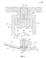
- FIG. 5 shows another portion of a transmission system 500 that includes the isolator 130 of FIGS. 1 and 2 and the isolator protection device 350 of FIG. 3 during normal operating conditions in accordance with certain example embodiments.
- Any reference numbers described below but not shown in FIG. 5 are hereby incorporated based on the reference number used in FIGS. 1-4 . Further, any description for a component with respect to FIGS. 1-4 can be incorporated into the corresponding component of the system 500 in FIG. 5 .
- the system 500 of FIG. 5 includes the isolator protection device 350 coupled to the arrester coupling device 123 and the stud 132 of the isolator 130 , as is the case during normal operating conditions.
- the outer surface of the arrester coupling device 123 in FIG. 5 is threadably coupled to the coupling feature 394 of the top wall 396 of the housing 380 of the isolator protection device 350 and to the arrester body 122 .
- the system 500 of FIG. 5 also shows that the coupling device 134 that extends outward from the top of the isolator body 131 is threadably coupled to an inner bore disposed in the distal end of the arrester coupling device 123 .
- the coupling device 134 can have any of a number of widths, including but not limited to be approximately 3 ⁇ 8 inches.
- the proximal end of the coupling device 134 can have a head (not shown) that anchors the coupling device 134 into the isolator body 131 .
- the coupling device 134 can be coupled to the isolator body 131 in one or more other ways.
- the coupling device 134 can be held within the isolator body 131 by epoxy.
- the isolator body 131 is disposed entirely within the cavity 393 formed by the side walls 392 of the isolator protection device 350 .
- the height 139 and the width 138 of the isolator body 131 is less than the height 384 and the width 385 , respectively, of the cavity 393 formed by the side walls 392 and the top wall 396 of the housing 380 .
- the optional nut 464 is also shown threadably coupled to the arrester coupling device 123 and disposed between the housing 380 and the arrester body 122 .
- one or more other optional components can be coupled to the arrester coupling device 123 and/or disposed between the housing 380 and the arrester body 122 .
- the securing device 370 of the isolator protection device 350 is threadably coupled to the stud 132 that extends outward from the distal end of the isolator body 131 .
- the proximal end of the stud 132 can have a head 133 that anchors the stud 132 into the isolator body 131 .
- the stud 132 can be coupled to the isolator body 131 in one or more other ways.
- the stud 132 can be held within the isolator body 131 by epoxy.
- the securing device 370 is disposed within the cavity 393 .
- the width 373 of the securing device 370 is substantially the same as or slightly less than the width 385 of the cavity 393 , the stud 132 of the isolator 130 is held firmly in place within the cavity 393 .
- any lateral forces applied by be ground conductor 140 and/or the tether 142 which are coupled to a more distal portion of the stud 132 compared to the securing device 370 , have little to no effect on the mechanical integrity of the isolator 130 (and the isolator body 131 in particular) during normal operating conditions.
- the tether 142 and the ground conductor 140 can be coupled to the stud 132 in a number of ways.
- the distal end of the ground conductor 140 of the tether 142 is coupled to a terminating device 144
- the distal end (in this case the distal link 143 ) of the tether 142 is coupled to a connection bar 136 .
- the resulting configuration at the distal end of the stud 132 includes a spacer 135 coupled to (or disposed over) the stud 332 .
- the spacer 135 is disposed between the securing device 370 and the terminating device 144 .
- connection bar 136 is disposed between the terminating device 144 and a nut 137 .
- the connection bar 136 can be used to securely couple the tether 142 and the ground conductor 140 to the stud 132 , and provide proper clearance of the tether 142 and the ground conductor 140 from the housing 380 of the isolator protection device 350 .
- FIG. 6 shows a system 600 that includes the system of FIG. 5 shortly after a fault condition in accordance with certain example embodiments.
- the system 600 of FIG. 6 is shown in a fault state.
- the system 600 of FIG. 6 is substantially the same as the system 500 of FIG. 5 , except as described below.
- the stud 132 (as well as the optional head 133 ) has become physically separated from the isolator body 131 . Consequently, the securing device 370 is physically removed from the cavity 393 and physically separates from the rest of the isolator protection device 350 .
- the securing device 370 is physically removed from the cavity 393 because the securing device 370 is mechanically coupled to the stud 132 .
- the securing device 370 merely abuts against or does not physically contact the at least one wall 392 of the housing 380 during normal operating conditions, then the securing device 370 (and so the stud 132 ) can more easily be ejected from the cavity 393 when a fault condition occurs. Further, the housing 380 can be substantially undamaged as a result of the stud 132 and the securing device 370 being ejected from the cavity 393 when a fault condition occurs.
- FIG. 7 shows yet another portion of a transmission system 700 that includes the isolator 130 of FIGS. 1 and 2 and an isolator protection device 750 during normal operating conditions in accordance with certain example embodiments.
- Any reference numbers described below but not shown in FIG. 7 are hereby incorporated based on the reference number used in FIGS. 1-6 . Further, any description for a component with respect to FIGS. 1-6 can be incorporated into the corresponding component of the system 700 in FIG. 7 .
- the isolator protection device 750 in the system 700 of FIG. 7 differs from the isolator protection device 350 of FIG. 3 in that the securing device 770 is configured differently. Instead of a disc the securing device 770 of the isolator protection device 750 of FIG. 7 includes a potting compound 768 that fills the cavity 793 and surrounds at least a portion of the isolator 730 .
- a potting compound 768 is any material (liquid, solid) that can fill at least a portion of the cavity 793 and one or more components (e.g., the isolator body 731 , the stud 732 ) of the isolator 730 stable within the housing 780 of the isolator protection device 750 during normal operating conditions.
- the potting compound 768 can be specifically designed to remain solid and within the cavity 793 during normal operating conditions, and yet also break apart or otherwise allow the stud 732 (with or without a portion of the isolator housing 731 ) to be released during a fault condition when the isolator 730 operates.
- the potting compound 768 can be designed to break apart or liquefy when its temperature (driven by an explosion of the isolator housing 731 ) exceeds a certain threshold temperature.
- some or all of the potting compound 768 can be designed to fracture or otherwise break apart when the pressure (driven by an explosion of the isolator housing 731 ) that it is exposed to exceeds a certain threshold pressure.
- the inner surface 789 of the side wall 792 can be coated with a special material to allow the potting compound 768 to more easily fall out of the housing 780 when the isolator 730 operates.
- the inner surface 789 of the side wall 792 of the housing 780 can be featureless (e.g., smooth) also to allow the potting compound 768 to more easily fall out of the housing 780 when the isolator 730 operates.
- the securing device 770 of the isolator protection device 750 of FIG. 7 is designed to secure, at least in part, the stud 732 to the isolator body 731 during normal operating conditions. Further, the securing device 770 of the isolator protection device 750 of FIG. 7 is designed to release the stud 732 during a fault condition, which allows the stud 732 to become decoupled from the isolator body 731 during the fault condition.
- FIG. 8 shows a system 800 that includes the system of FIG. 7 shortly after a fault condition in accordance with certain example embodiments.
- the system 800 of FIG. 8 is shown in a fault state.
- the system 800 of FIG. 8 is substantially the same as the system 700 of FIG. 7 , except as described below.
- the potting compound 768 fractures (especially the potting compound 768 proximate to where the stud 732 couples to the isolator body 731 ).
- the stud 732 (as well as the optional head 733 ) can become physically separated from the isolator body 731 .
- at least a portion of the potting compound 768 (the securing device 770 ) is physically removed from the cavity 793 and physically separates from the rest of the isolator protection device 750 as a result of the fault condition.
- Example embodiments provide increased mechanical stability of the isolator of an arrester, extending the useful life and reliability of the isolator and the arrester as a whole.
- Example embodiments provide a number of benefits. Examples of such benefits include, but are not limited to reduced downtime of equipment, lower maintenance costs, avoidance of catastrophic failure, improved maintenance panning, improved efficiency of one or more devices and/or other portions of an example transmission system, extended useful life of one or more components of an example transmission system, and reduced cost of labor and materials.
Landscapes
- Emergency Protection Circuit Devices (AREA)
- Thermistors And Varistors (AREA)
- Gas-Insulated Switchgears (AREA)
- Insulators (AREA)
Abstract
Description
Claims (20)
Priority Applications (1)
| Application Number | Priority Date | Filing Date | Title |
|---|---|---|---|
| US14/868,764 US9438024B2 (en) | 2014-09-30 | 2015-09-29 | Isolator protection device |
Applications Claiming Priority (2)
| Application Number | Priority Date | Filing Date | Title |
|---|---|---|---|
| US201462057559P | 2014-09-30 | 2014-09-30 | |
| US14/868,764 US9438024B2 (en) | 2014-09-30 | 2015-09-29 | Isolator protection device |
Publications (2)
| Publication Number | Publication Date |
|---|---|
| US20160094021A1 US20160094021A1 (en) | 2016-03-31 |
| US9438024B2 true US9438024B2 (en) | 2016-09-06 |
Family
ID=55585476
Family Applications (1)
| Application Number | Title | Priority Date | Filing Date |
|---|---|---|---|
| US14/868,764 Active US9438024B2 (en) | 2014-09-30 | 2015-09-29 | Isolator protection device |
Country Status (6)
| Country | Link |
|---|---|
| US (1) | US9438024B2 (en) |
| EP (1) | EP3201936B1 (en) |
| CN (1) | CN107077993B (en) |
| AU (1) | AU2015324017B2 (en) |
| BR (1) | BR112017006545B1 (en) |
| WO (1) | WO2016053977A1 (en) |
Cited By (1)
| Publication number | Priority date | Publication date | Assignee | Title |
|---|---|---|---|---|
| US11025036B2 (en) | 2018-03-12 | 2021-06-01 | Paul Lindemulder | Hot stick quick connect surge arrester assembly |
Families Citing this family (3)
| Publication number | Priority date | Publication date | Assignee | Title |
|---|---|---|---|---|
| US10388438B2 (en) * | 2013-03-15 | 2019-08-20 | Richards Manufacturing Company Sales, Inc. | Push on arrester |
| AU2020264443B2 (en) * | 2019-04-29 | 2025-04-17 | Hubbell Incorporated | Disconnector device and overvoltage protection assembly including the same |
| US12537338B2 (en) | 2022-07-22 | 2026-01-27 | Richards Mfg. Co. Sales, Llc | Obstruction feature for ensuring proper connectivity in a cable assembly |
Citations (6)
| Publication number | Priority date | Publication date | Assignee | Title |
|---|---|---|---|---|
| US3662083A (en) * | 1969-04-15 | 1972-05-09 | Detude De Lenergie Nucleaire E | Lightning conductor |
| EP0548333A1 (en) | 1991-07-10 | 1993-06-30 | Joslyn Corp | OVERVOLTAGE LIMITER WITH ERROR DISPLAY. |
| US5998731A (en) * | 1997-01-16 | 1999-12-07 | Etsuko Takamura | Absorbed type lightning rod and absorbed type lightning discharging apparatus |
| US20040239471A1 (en) | 2003-05-29 | 2004-12-02 | Hubbell Incorporated | Arrester disconnector assembly having a capacitor |
| US7236341B1 (en) * | 2006-04-19 | 2007-06-26 | Lightning Eliminators & Consultants, Inc. | Lightning termination preventer |
| US20110216463A1 (en) | 2010-03-08 | 2011-09-08 | Kester Jeffrey J | Line protection systems |
Family Cites Families (3)
| Publication number | Priority date | Publication date | Assignee | Title |
|---|---|---|---|---|
| DE2738544A1 (en) * | 1977-08-26 | 1979-03-01 | Transformatoren Union Ag | Disconnection of mains from overloaded overvoltage shunts - by separation of contacts in earth lead due to softening or melting material holding contacts together |
| US5400207A (en) * | 1993-11-18 | 1995-03-21 | Hubbell Incorporated | Isolator-arrester assembly |
| DE102011052390A1 (en) * | 2011-08-03 | 2013-02-07 | Phoenix Contact Gmbh & Co. Kg | Thermal overload protection device |
-
2015
- 2015-09-29 BR BR112017006545-2A patent/BR112017006545B1/en active IP Right Grant
- 2015-09-29 AU AU2015324017A patent/AU2015324017B2/en active Active
- 2015-09-29 WO PCT/US2015/052845 patent/WO2016053977A1/en not_active Ceased
- 2015-09-29 US US14/868,764 patent/US9438024B2/en active Active
- 2015-09-29 CN CN201580058299.9A patent/CN107077993B/en active Active
- 2015-09-29 EP EP15847186.2A patent/EP3201936B1/en active Active
Patent Citations (6)
| Publication number | Priority date | Publication date | Assignee | Title |
|---|---|---|---|---|
| US3662083A (en) * | 1969-04-15 | 1972-05-09 | Detude De Lenergie Nucleaire E | Lightning conductor |
| EP0548333A1 (en) | 1991-07-10 | 1993-06-30 | Joslyn Corp | OVERVOLTAGE LIMITER WITH ERROR DISPLAY. |
| US5998731A (en) * | 1997-01-16 | 1999-12-07 | Etsuko Takamura | Absorbed type lightning rod and absorbed type lightning discharging apparatus |
| US20040239471A1 (en) | 2003-05-29 | 2004-12-02 | Hubbell Incorporated | Arrester disconnector assembly having a capacitor |
| US7236341B1 (en) * | 2006-04-19 | 2007-06-26 | Lightning Eliminators & Consultants, Inc. | Lightning termination preventer |
| US20110216463A1 (en) | 2010-03-08 | 2011-09-08 | Kester Jeffrey J | Line protection systems |
Non-Patent Citations (1)
| Title |
|---|
| The International Search Report and Written Opinion from Corresponding International Application PCT/US2015/052845, mailed Jan. 21, 2016 (6 pages). |
Cited By (1)
| Publication number | Priority date | Publication date | Assignee | Title |
|---|---|---|---|---|
| US11025036B2 (en) | 2018-03-12 | 2021-06-01 | Paul Lindemulder | Hot stick quick connect surge arrester assembly |
Also Published As
| Publication number | Publication date |
|---|---|
| AU2015324017A1 (en) | 2017-04-27 |
| US20160094021A1 (en) | 2016-03-31 |
| AU2015324017B2 (en) | 2020-09-10 |
| BR112017006545A2 (en) | 2018-01-23 |
| BR112017006545B1 (en) | 2022-08-09 |
| CN107077993A (en) | 2017-08-18 |
| CN107077993B (en) | 2019-08-09 |
| EP3201936A1 (en) | 2017-08-09 |
| EP3201936A4 (en) | 2018-07-04 |
| EP3201936B1 (en) | 2021-11-03 |
| WO2016053977A1 (en) | 2016-04-07 |
Similar Documents
| Publication | Publication Date | Title |
|---|---|---|
| US5220480A (en) | Low voltage, high energy surge arrester for secondary applications | |
| US6876533B1 (en) | Surge suppressor enclosure and fusing system | |
| US9557349B2 (en) | Measuring system for continuously monitoring a high-voltage bushing | |
| US5583729A (en) | Terminal bushing having integral overvoltage and overcurrent protection | |
| US20210344192A1 (en) | Surge protection device and system | |
| US6055147A (en) | Apparatus for providing independent over-current protection to a plurality of electrical devices and transient-voltage suppression system employing the apparatus | |
| US9438024B2 (en) | Isolator protection device | |
| US20080068122A1 (en) | Arrester Disconnector Assembly Minimizing Explosive Separation | |
| US9824800B2 (en) | Multi-terminal surge arrester | |
| AU2021200625A1 (en) | Electrically insulated tethers for transmission line arresters | |
| CN108428526A (en) | A kind of lightning arrester core body and arrester | |
| US7656639B2 (en) | Retainer for surge arrester disconnector | |
| US9543745B2 (en) | Arrester bypass devices | |
| US4400754A (en) | Spark arrestor | |
| KR200422796Y1 (en) | Multi-core ground rod | |
| CA2610127A1 (en) | Fuse having a plurality of configurable thermal ceilings | |
| KR101390387B1 (en) | System preventing thermal runway for varistor | |
| KR200449360Y1 (en) | Bushing Shield | |
| KR20190001610U (en) | The connecting apparatus of lead wire | |
| KR200306066Y1 (en) | An outlet with surge voltage prevention function | |
| JP2004200092A (en) | Arrestor with gap |
Legal Events
| Date | Code | Title | Description |
|---|---|---|---|
| AS | Assignment |
Owner name: COOPER TECHNOLOGIES COMPANY, TEXAS Free format text: ASSIGNMENT OF ASSIGNORS INTEREST;ASSIGNORS:RAMARGE, MICHAEL M.;SMITH, TIMOTHY STEPHEN;REEL/FRAME:036798/0876 Effective date: 20150928 |
|
| FEPP | Fee payment procedure |
Free format text: PAYOR NUMBER ASSIGNED (ORIGINAL EVENT CODE: ASPN); ENTITY STATUS OF PATENT OWNER: LARGE ENTITY |
|
| STCF | Information on status: patent grant |
Free format text: PATENTED CASE |
|
| AS | Assignment |
Owner name: EATON INTELLIGENT POWER LIMITED, IRELAND Free format text: ASSIGNMENT OF ASSIGNORS INTEREST;ASSIGNOR:COOPER TECHNOLOGIES COMPANY;REEL/FRAME:048207/0819 Effective date: 20171231 |
|
| AS | Assignment |
Owner name: EATON INTELLIGENT POWER LIMITED, IRELAND Free format text: CORRECTIVE ASSIGNMENT TO CORRECT THE COVER SHEET TO REMOVE APPLICATION NO. 15567271 PREVIOUSLY RECORDED ON REEL 048207 FRAME 0819. ASSIGNOR(S) HEREBY CONFIRMS THE ASSIGNMENT;ASSIGNOR:COOPER TECHNOLOGIES COMPANY;REEL/FRAME:048655/0114 Effective date: 20171231 |
|
| MAFP | Maintenance fee payment |
Free format text: PAYMENT OF MAINTENANCE FEE, 4TH YEAR, LARGE ENTITY (ORIGINAL EVENT CODE: M1551); ENTITY STATUS OF PATENT OWNER: LARGE ENTITY Year of fee payment: 4 |
|
| MAFP | Maintenance fee payment |
Free format text: PAYMENT OF MAINTENANCE FEE, 8TH YEAR, LARGE ENTITY (ORIGINAL EVENT CODE: M1552); ENTITY STATUS OF PATENT OWNER: LARGE ENTITY Year of fee payment: 8 |