US9427797B2 - Up-drawing continuous casting apparatus and up-drawing continuous casting method - Google Patents
Up-drawing continuous casting apparatus and up-drawing continuous casting method Download PDFInfo
- Publication number
- US9427797B2 US9427797B2 US14/638,348 US201514638348A US9427797B2 US 9427797 B2 US9427797 B2 US 9427797B2 US 201514638348 A US201514638348 A US 201514638348A US 9427797 B2 US9427797 B2 US 9427797B2
- Authority
- US
- United States
- Prior art keywords
- molten metal
- casting
- shape determining
- determining member
- solidification interface
- Prior art date
- Legal status (The legal status is an assumption and is not a legal conclusion. Google has not performed a legal analysis and makes no representation as to the accuracy of the status listed.)
- Expired - Fee Related, expires
Links
- 238000009749 continuous casting Methods 0.000 title claims abstract description 27
- 238000000034 method Methods 0.000 title claims description 30
- 229910052751 metal Inorganic materials 0.000 claims abstract description 158
- 239000002184 metal Substances 0.000 claims abstract description 158
- 238000007711 solidification Methods 0.000 claims abstract description 122
- 230000008023 solidification Effects 0.000 claims abstract description 122
- 238000005266 casting Methods 0.000 claims abstract description 111
- 230000000717 retained effect Effects 0.000 claims abstract description 47
- 238000003384 imaging method Methods 0.000 claims abstract description 25
- 239000000112 cooling gas Substances 0.000 claims description 26
- 239000003086 colorant Substances 0.000 claims description 6
- 238000001816 cooling Methods 0.000 claims description 5
- 230000010355 oscillation Effects 0.000 description 23
- 239000007858 starting material Substances 0.000 description 17
- 238000001514 detection method Methods 0.000 description 7
- XKRFYHLGVUSROY-UHFFFAOYSA-N Argon Chemical compound [Ar] XKRFYHLGVUSROY-UHFFFAOYSA-N 0.000 description 2
- IJGRMHOSHXDMSA-UHFFFAOYSA-N Atomic nitrogen Chemical compound N#N IJGRMHOSHXDMSA-UHFFFAOYSA-N 0.000 description 2
- 229910052782 aluminium Inorganic materials 0.000 description 2
- XAGFODPZIPBFFR-UHFFFAOYSA-N aluminium Chemical compound [Al] XAGFODPZIPBFFR-UHFFFAOYSA-N 0.000 description 2
- 238000010586 diagram Methods 0.000 description 2
- 238000010998 test method Methods 0.000 description 2
- 229910000838 Al alloy Inorganic materials 0.000 description 1
- 239000003570 air Substances 0.000 description 1
- 229910045601 alloy Inorganic materials 0.000 description 1
- 239000000956 alloy Substances 0.000 description 1
- 229910052786 argon Inorganic materials 0.000 description 1
- 239000000919 ceramic Substances 0.000 description 1
- 239000000470 constituent Substances 0.000 description 1
- 230000007423 decrease Effects 0.000 description 1
- 230000007547 defect Effects 0.000 description 1
- 238000006073 displacement reaction Methods 0.000 description 1
- 230000000694 effects Effects 0.000 description 1
- 230000003628 erosive effect Effects 0.000 description 1
- 238000010191 image analysis Methods 0.000 description 1
- 238000010348 incorporation Methods 0.000 description 1
- 229910052757 nitrogen Inorganic materials 0.000 description 1
- 239000007787 solid Substances 0.000 description 1
- 238000005507 spraying Methods 0.000 description 1
- 239000010935 stainless steel Substances 0.000 description 1
- 229910001220 stainless steel Inorganic materials 0.000 description 1
Images


Classifications
-
- B—PERFORMING OPERATIONS; TRANSPORTING
- B22—CASTING; POWDER METALLURGY
- B22D—CASTING OF METALS; CASTING OF OTHER SUBSTANCES BY THE SAME PROCESSES OR DEVICES
- B22D11/00—Continuous casting of metals, i.e. casting in indefinite lengths
- B22D11/14—Plants for continuous casting
- B22D11/142—Plants for continuous casting for curved casting
-
- B—PERFORMING OPERATIONS; TRANSPORTING
- B22—CASTING; POWDER METALLURGY
- B22D—CASTING OF METALS; CASTING OF OTHER SUBSTANCES BY THE SAME PROCESSES OR DEVICES
- B22D11/00—Continuous casting of metals, i.e. casting in indefinite lengths
- B22D11/01—Continuous casting of metals, i.e. casting in indefinite lengths without moulds, e.g. on molten surfaces
-
- B—PERFORMING OPERATIONS; TRANSPORTING
- B22—CASTING; POWDER METALLURGY
- B22D—CASTING OF METALS; CASTING OF OTHER SUBSTANCES BY THE SAME PROCESSES OR DEVICES
- B22D11/00—Continuous casting of metals, i.e. casting in indefinite lengths
- B22D11/12—Accessories for subsequent treating or working cast stock in situ
- B22D11/1206—Accessories for subsequent treating or working cast stock in situ for plastic shaping of strands
-
- B—PERFORMING OPERATIONS; TRANSPORTING
- B22—CASTING; POWDER METALLURGY
- B22D—CASTING OF METALS; CASTING OF OTHER SUBSTANCES BY THE SAME PROCESSES OR DEVICES
- B22D11/00—Continuous casting of metals, i.e. casting in indefinite lengths
- B22D11/14—Plants for continuous casting
- B22D11/141—Plants for continuous casting for vertical casting
-
- B—PERFORMING OPERATIONS; TRANSPORTING
- B22—CASTING; POWDER METALLURGY
- B22D—CASTING OF METALS; CASTING OF OTHER SUBSTANCES BY THE SAME PROCESSES OR DEVICES
- B22D11/00—Continuous casting of metals, i.e. casting in indefinite lengths
- B22D11/14—Plants for continuous casting
- B22D11/145—Plants for continuous casting for upward casting
-
- B—PERFORMING OPERATIONS; TRANSPORTING
- B22—CASTING; POWDER METALLURGY
- B22D—CASTING OF METALS; CASTING OF OTHER SUBSTANCES BY THE SAME PROCESSES OR DEVICES
- B22D11/00—Continuous casting of metals, i.e. casting in indefinite lengths
- B22D11/16—Controlling or regulating processes or operations
- B22D11/22—Controlling or regulating processes or operations for cooling cast stock or mould
- B22D11/225—Controlling or regulating processes or operations for cooling cast stock or mould for secondary cooling
Definitions
- the invention relates to an up-drawing continuous casting apparatus and an up-drawing continuous casting method.
- JP 2012-61518 A proposes a free casting method as a technological up-drawing continuous casting method that does not require a mold.
- a starter is first dipped into the surface of molten metal (a molten metal surface), and then when the starter is drawn up, molten metal is also drawn up following the starter by surface tension and the surface film of the molten metal.
- a casting that has a desired sectional shape is able to be continuously cast by drawing up the molten metal through a shape determining member arranged near the molten metal surface, and cooling the drawn up molten metal.
- the sectional shape and the shape in the longitudinal direction are both determined by a mold.
- the solidified metal i.e., the casting
- the shape determining member in the free casting method determines only the sectional shape of the casting.
- the shape in the longitudinal direction is not determined. Therefore, castings of various shapes in the longitudinal direction are able to be obtained by drawing the starter up while moving the starter (or the shape determining member) in a horizontal direction.
- JP 2012-61518 A describes a hollow casting (i.e., a pipe) formed in a zigzag shape or a helical shape, not a linear shape in the longitudinal direction.
- the inventors have found that, because the surface of the drawn-up molten metal oscillates (more specifically, greatly fluctuates in short fluctuation cycles) and the surface of the casting formed by the molten metal solidifying does not oscillate much at all (more specifically, fluctuates little in long fluctuation cycles), the solidification interface can be determined based on whether there is oscillation.
- the position of the solidification interface is low, oscillation of the drawn-up molten metal is small and is difficult to detect, so it is difficult to determine the solidification interface based on whether there is oscillation.
- the position of the solidification interface is low, the solidification interface may not be able to be controlled to within an appropriate reference range.
- the invention thus provides an up-drawing continuous casting apparatus and an up-drawing continuous casting method in which a solidification interface can be controlled to within an appropriate reference range even if the solidification interface is low, and which therefore obtain excellent dimensional accuracy and surface quality of a casting.
- a first aspect of the invention relates to an up-drawing continuous casting apparatus that includes a holding furnace that holds molten metal; a shape determining member that is arranged above a molten metal surface of the molten metal held in the holding furnace, and that determines a sectional shape of a cast casting by the molten metal passing through the shape determining member, the shape determining member including a pattern provided on an upper surface of the shape determining member; an imaging portion configured to capture an image of the pattern that is reflected onto both retained molten metal that has passed through the shape determining member, and the casting formed by the retained molten metal solidifying; an image analyzing portion configured to determine a solidification interface from the image; and a casting controlling portion configured to change a casting condition when the solidification interface determined by the image analyzing portion is not within a predetermined reference range.
- the pattern provided on the upper surface of the solidification interface is reflected onto the molten metal that has passed through the shape determining member, so the brightness of the molten metal surface greatly changes with even the slightest oscillation of the molten metal. Therefore, the solidification interface is able to be determined even if the solidification interface is low and the oscillation of the molten metal is small. As a result, the solidification interface is able to be controlled to within an appropriate reference range even if the solidification interface is low.
- a second aspect of the invention relates to an up-drawing continuous casting method that includes arranging a shape determining member that determines a sectional shape of a cast casting above a molten metal surface of molten metal held in a holding furnace, and drawing up the molten metal while passing the molten metal through the shape determining member, the shape determining member including a pattern provided on an upper surface of the shape determining member.
- This up-drawing continuous casting method also includes capturing an image of the pattern that is reflected onto both retained molten metal that has passed through the shape determining member, and the casting formed by the retained molten metal solidifying; determining a solidification interface from the image; and changing a casting condition when the determined solidification interface is not within a predetermined reference range.
- the pattern provided on the upper surface of the solidification interface is reflected onto the molten metal that has passed through the shape determining member, so the brightness of the molten metal surface greatly changes with even the slightest oscillation of the molten metal. Therefore, the solidification interface is able to be determined even if the solidification interface is low and the oscillation of the molten metal is small. As a result, the solidification interface is able to be controlled to within an appropriate reference range even if the solidification interface is low.
- the invention is thus able to provide an up-drawing continuous casting apparatus and an up-drawing continuous casting method in which a solidification interface can be controlled to within an appropriate reference range even if the solidification interface is low, and which therefore obtain excellent dimensional accuracy and surface quality of a casting.
- FIG. 1 is a sectional view showing a frame format of a free casting apparatus according to a first example embodiment of the invention
- FIG. 2 is a plan view of a shape determining member according to the first example embodiment
- FIG. 3 is a block diagram of a solidification interface control system provided in the free casting apparatus according to the first example embodiment
- FIG. 4 is a view of three example images of an area near a solidification interface
- FIG. 5 is a flowchart illustrating a solidification interface control method according to the first example embodiment
- FIG. 6 is a plan view of a modified example of the shape determining member according to the first example embodiment
- FIG. 7 is a plan view of the modified example of the shape determining member according to the first example embodiment.
- FIG. 8 is a side view of the modified example of the shape determining member according to the first example embodiment
- FIG. 9 is a view of an image of the shape determining member used in a test.
- FIG. 10 is a view of example images of an area near the solidification interface in a case in which a pattern is not applied to an upper surface of the shape determining member, and a case in which the pattern is applied to the upper surface of the shape determining member;
- FIG. 11 is a view illustrating a test method
- FIG. 12 is a view of the relationship between the position of the solidification interface and interface detection rate
- FIG. 13 is a plan view of a shape determining member according to a second example embodiment of the invention.
- FIG. 14 is a side view of the shape determining member of the second example embodiment.
- FIG. 15 is a flowchart illustrating a solidification interface control method according to the second example embodiment.
- FIG. 1 is a sectional view showing a frame format of the free casting apparatus according to the first example embodiment.
- the free casting apparatus according to the first example embodiment includes a molten metal holding furnace 101 , a shape determining member 102 , a support rod 104 , an actuator 105 , a cooling gas nozzle 106 , a cooling gas supplying portion 107 , an up-drawing machine 108 , and an imaging portion (camera) 109 .
- a molten metal holding furnace 101 As shown in FIG. 1 , the free casting apparatus according to the first example embodiment includes a molten metal holding furnace 101 , a shape determining member 102 , a support rod 104 , an actuator 105 , a cooling gas nozzle 106 , a cooling gas supplying portion 107 , an up-drawing machine 108 , and an imaging portion (camera) 109 .
- FIG. 1 is a sectional view showing a frame format of the free casting apparatus according to the first example embodiment.
- a right-handed xyz coordinate system is shown for descriptive purposes to illustrate the positional relationship of the constituent elements.
- the x-y plane in FIG. 1 forms a horizontal plane, and the z-axis direction is the vertical direction. More specifically, the plus direction of the z-axis is vertically upward.
- the molten metal holding furnace 101 holds molten metal M 1 such as aluminum or an aluminum alloy, for example, and keeps it at a predetermined temperature at which the molten metal M 1 has fluidity.
- molten metal is not replenished into the molten metal holding furnace 101 during casting, so the surface of the molten metal M 1 (i.e., the molten metal surface level) drops as casting proceeds.
- molten metal may also be replenished into the molten metal holding furnace 101 when necessary during casting so that the molten metal surface level is kept constant.
- the position of a solidification interface SIF can be raised by increasing a set temperature of the molten metal holding furnace 101 , and lowered by reducing the set temperature of the molten metal holding furnace 101 .
- the molten metal M 1 may be another metal or alloy other than aluminum.
- the shape determining member 102 is made of ceramic or stainless steel, for example, and is arranged above the molten metal M 1 .
- the shape determining member 102 determines the sectional shape of a cast casting M 3 .
- the casting M 3 shown in FIG. 1 is a solid casting (a plate) having a rectangular cross-section in the horizontal direction (hereinafter, simply referred to as “transverse section”). Naturally, the sectional shape of the casting M 3 is not particularly limited.
- the casting M 3 may also be a hollow casting of a round pipe or a square pipe or the like.
- a main surface (a lower surface) on a lower side of the shape determining member 102 is arranged contacting the molten metal surface. Therefore, an oxide film that forms on the surface of the molten metal M 1 and foreign matter floating on the surface of the molten metal M 1 are able to be prevented from getting mixed into the casting M 3 .
- the lower surface of the shape determining member 102 may also be arranged a predetermined distance away from the molten metal surface. When the shape determining member 102 is arranged away from the molten metal surface, heat deformation and erosion of the shape determining member 102 are inhibited, so the durability of the shape determining member 102 improves.
- FIG. 2 is a plan view of the shape determining member 102 according to the first example embodiment.
- the sectional view of the shape determining member 102 in FIG. 1 corresponds to a sectional view taken along line I-I in FIG. 2 .
- the shape determining member 102 has a rectangular planar shape, for example, and has a rectangular open portion (a molten metal passage portion 103 ) having a thickness t1 and a width w1 through which the molten metal passes in the center portion.
- the xyz coordinates in FIG. 2 match those in FIG. 1 .
- a pattern P is applied to an upper surface (i.e., the surface on the upper side) of the shape determining member 102 . More specifically, a striped pattern P formed by a plurality of colors (black and white in this case) is applied to the upper surface of the shape determining member 102 .
- the pattern P is preferably applied such that the pattern P has slimness (density) where the colors are enough to be able to be identified by an image analyzing portion 110 .
- the pattern P is applied by applying heat resistance ink to the upper surface of the shape determining member 102 , for example. The specific effects of the pattern P will be described later.
- the molten metal M 1 is drawn up following the starter ST while maintaining its outer shape, by the surface tension and the surface film of the molten metal M 1 , and passes through the molten metal passage portion 103 of the shape determining member 102 .
- external force is applied to the molten metal M 1 from the shape determining member 102 , such that the sectional shape of the casting M 3 is determined.
- the molten metal that is drawn up from the molten metal surface following the starter ST (or the casting M 3 that is formed by the molten metal M 1 drawn up following the starter ST solidifying) by the surface tension and the surface film of the molten metal M 1 will be referred to as “retained molten metal M 2 ”.
- the boundary between the casting M 3 and the retained molten metal M 2 is a solidification interface SIF.
- the support rod 104 supports the shape determining member 102 .
- the support rod 104 is connected to the actuator 105 .
- the shape determining member 102 is able to move up and down (i.e., in the vertical direction; the z-axis direction) via the support rod 104 , by the actuator 105 . According to this kind of structure, the shape determining member 102 is able to be moved downward as the molten metal surface level drops as casting proceeds.
- a cooling gas nozzle (a cooling portion) 106 is cooling means for spraying cooling gas (e.g., air, nitrogen, argon, or the like) supplied from the cooling gas supplying portion 107 at the casting M 3 to cool the casting M 3 .
- the position of the solidification interface SIF is able to be lowered by increasing the flow rate of the cooling gas, and raised by reducing the flow rate of the cooling gas.
- the cooling gas nozzle 106 is also able to be moved up and down (i.e., in the vertical direction; in the z-axis direction) and horizontally (i.e., in the x-axis direction and the y-axis direction).
- the cooling gas nozzle 106 can be moved downward, in concert with the movement of the shape determining member 102 , as the molten metal surface level drops as casting proceeds.
- the cooling gas nozzle 106 can be moved horizontally, in concert with horizontal movement of the up-drawing machine 108 .
- the casting M 3 is formed by the retained molten metal M 2 near the solidification interface SIF progressively solidifying from the upper side (i.e., a plus side in the z-axis direction) toward lower side (i.e., a minus side in the z-axis direction), by cooling the starter ST and the casting M 3 with the cooling gas, while drawing the casting M 3 up with the up-drawing machine 108 that is connected to the starter ST.
- the position of the solidification interface SIF is able to be raised by increasing the up-drawing speed with the up-drawing machine 108 , and lowered by reducing the up-drawing speed.
- the retained molten metal M 2 is able to be drawn out diagonally by drawing the casting M 3 up while moving the up-drawing machine 108 horizontally (in the x-axis direction and the y-axis direction). Therefore, the longitudinal shape of the casting M 3 is able to be freely changed.
- the longitudinal shape of the casting M 3 may also be freely changed by moving the shape determining member 102 horizontally, instead of by moving the up-drawing machine 108 horizontally.
- the imaging portion 109 continuously monitors the area near the solidification interface SIF that is the boundary between the casting M 3 and the retained molten metal M 2 , during casting.
- the imaging portion 109 is arranged at a position and angle such that it is able to capture the pattern P reflected onto the surfaces of both the retained molten metal M 2 and the casting M 3 (or more preferably, the entire area used for image analysis).
- the pattern P is applied to a position and area that satisfies this.
- the imaging portion 109 successively captures an image of not only the surfaces of both the retained molten metal M 2 and the casting M 3 , but also of the pattern P reflected onto these surfaces.
- the imaging portion 109 is arranged looking diagonally down and facing on the solidification interface SIF from above the solidification interface SIF.
- the imaging portion 109 may also be configured to move according to this change.
- the solidification interface SIF is able to be determined from the image captured by the imaging portion 109 , as will be described in detail later.
- FIG. 3 is a block diagram of the solidification interface control system provided in the free casting apparatus according to the first example embodiment.
- This solidification interface control system is designed to keep the position (height) of the solidification interface SIF within a predetermined reference range.
- this solidification interface control system includes the imaging portion 109 , an image analyzing portion 110 , a casting controlling portion 111 , the up-drawing machine 108 , the molten metal holding furnace 101 , and the cooling gas supplying portion 107 .
- the imaging portion 109 , the up-drawing machine 108 , the molten metal holding furnace 101 , and the cooling gas supplying portion 107 have been described with reference to FIG. 1 , so detailed descriptions of these will be omitted here.
- the image analyzing portion 110 determines the solidification interface from an image captured by the imaging portion 109 . More specifically, the image analyzing portion 110 compares a plurality of images captured in succession, and determines a location where a brightness value of reflected light changes greatly in short fluctuation cycles, to be the surface of the retained molten metal M 2 which oscillates. On the other hand, the image analyzing portion 110 determines a location where the brightness value of the reflected light changes only slightly in long fluctuation cycles, i.e., a location where there is not much oscillation, to be the surface of the casting M 3 . As a result, the image analyzing portion 110 is able to determine the solidification interface based on whether there is oscillation (or more specifically, the fluctuation cycle of the oscillation and fluctuation range of the oscillation).
- the pattern P is applied to the upper surface of the shape determining member 102 .
- This pattern P is reflected onto the retained molten metal M 2 , so the brightness of the surface of the retained molten metal M 2 changes greatly when the retained molten metal M 2 oscillates slightly. Therefore, the solidification interface is able to be determined even when the molten metal surface is low and oscillation of the molten metal surface is small.
- FIG. 4 is a view of three example images of the area near the solidification interface.
- the example images in FIG. 4 are, in order from the top of FIG. 4 , an example image of a case in which the position of the solidification interface is above an upper limit, an example image of a case in which the position of the solidification interface is within the reference range, and an example image of a case in which the position of the solidification interface is below a lower limit As shown in the example image in the center of FIG.
- the image analyzing portion 110 determines a boundary portion between a region where oscillation is detected (i.e., molten metal), and a region where oscillation is so small that it is not detected (i.e., the casting), in the image captured by the imaging portion 109 , to be the solidification interface, for example.
- the casting controlling portion 111 includes a storing portion, not shown, that stores the reference range (the upper and lower limits) of the solidification interface position. Also, if the solidification interface determined by the image analyzing portion 110 is above the upper limit, the casting controlling portion 111 reduces the up-drawing speed of the up-drawing machine 108 , lowers the set temperature of the molten metal holding furnace 101 , or increases the flow rate of the cooling gas supplied from the cooling gas supplying portion 107 .
- the casting controlling portion 111 increases the up-drawing speed of the up-drawing machine 108 , raises the set temperature of the molten metal holding furnace 101 , or decreases the flow rate of the cooling gas supplied from the cooling gas supplying portion 107 .
- Control of these three conditions may simultaneously change two or more conditions, but changing only one condition makes control easier, and is thus preferable.
- the priority order of the three conditions may be set in advance, and they may be changed in order from that of the highest priority.
- the upper and lower limits of the solidification interface position will be described with reference to FIG. 4 .
- the upper limit of the solidification interface position can be determined by changing the height of the solidification interface, and examining in advance whether a “constriction” occurs in the retained molten metal M 2 .
- the position of the solidification interface is below the lower limit, as shown in the example image at the bottom of FIG. 4 , asperities occur on the surface of the casting M 3 and become shape defects.
- the lower limit of the solidification interface position can be determined by changing the height of the solidification interface, and examining in advance whether asperities occur on the surface of the casting M 3 . These asperities are thought to be solidified flakes that have formed inside the shape determining member 102 due to the solidification interface being too low.
- the free casting apparatus has the pattern P applied to the upper surface of the shape determining member 102 , and includes the imaging portion that captures an image of the pattern P that is reflected onto an area near the solidification interface, and an image analyzing portion that determines the solidification interface from this image. Because this pattern P is reflected onto the retained molten metal M 2 , the brightness of the surface of the retained molten metal M 2 greatly changes when the retained molten metal M 2 oscillates slightly. Therefore, the solidification interface is able to be determined even if the solidification interface is low and the oscillation of the molten metal is small. As a result, even if the solidification interface is low, feedback control for keeping the solidification interface within the predetermined reference range is able to be performed, so the dimensional accuracy and surface quality of the casting are able to be improved.
- the starter ST is lowered by the up-drawing machine 108 so that it passes through the molten metal passage portion 103 of the shape determining member 102 , and the tip end portion of the starter ST is dipped into the molten metal M 1 .
- the starter ST starts to be drawn up at a predetermined speed.
- the molten metal M 1 follows the starter ST and is drawn up from the molten metal surface by the surface film and surface tension, and forms the retained molten metal M 2 .
- the retained molten metal M 2 is formed in the molten metal passage portion 103 of the shape determining member 102 . That is, the shape determining member 102 gives the retained molten metal M 2 its shape.
- the starter ST (or the casting M 3 formed by the retained molten metal M 2 solidifying) is cooled by cooling gas blown from the cooling gas nozzle 106 .
- the retained molten metal M 2 is indirectly cooled and solidifies progressively from the upper side toward the lower side, thus forming the casting M 3 .
- the casting M 3 is able to be continuously cast.
- FIG. 5 is a flowchart illustrating the solidification interface control method according to the first example embodiment.
- the imaging portion 109 captures an image of the area near the solidification interface (step ST 1 ). Then, the image analyzing portion 110 analyzes the image captured by the imaging portion 109 (step ST 2 ). More specifically, the image analyzing portion 110 determines a location where the brightness value of reflected light changes greatly in short fluctuation cycles, to be the surface of the retained molten metal M 2 which oscillates, and determines a location where there is almost no oscillation to be the surface of the casting M 3 , by comparing a plurality of images captured in succession. Then the image analyzing portion 110 determines the boundary portion between a region where oscillation was detected and a region where oscillation was so small that it was not detected, in the image captured by the imaging portion 109 , to be the solidification interface.
- the pattern P is applied to the upper surface of the shape determining member 102 .
- This pattern P is reflected onto the retained molten metal M 2 , so the brightness of the surface of the retained molten metal M 2 changes greatly when the retained molten metal M 2 oscillates slightly. Therefore, the solidification interface is able to be determined even when the molten metal surface is low and the oscillation of the molten metal surface is small.
- the casting controlling portion 111 determines whether the position of the solidification interface determined by the image analyzing portion 110 is within the reference range (step ST 3 ). If the position of the solidification interface is not within the reference range (i.e., NO in step ST 3 ), the casting controlling portion 111 changes one of the conditions, i.e., the cooling gas flow rate, the casting speed, and the holding furnace set temperature (step ST 4 ). Then, the casting controlling portion 111 determines whether casting is complete (step ST 5 ).
- step ST 4 if the solidification interface determined by the image analyzing portion 110 is above the upper limit, the casting controlling portion 111 reduces the up-drawing speed of the up-drawing machine 108 , lowers the set temperature of the molten metal holding furnace 101 , or increases the flow rate of cooling gas supplied from the cooling gas supplying portion 107 .
- the casting controlling portion 111 increases the up-drawing speed of the up-drawing machine 108 , raises the set temperature of the molten metal holding furnace 101 , or reduces the flow rate of the cooling gas supplied from the cooling gas supplying portion 107 .
- step ST 3 If the position of the solidification interface is within the reference range (i.e., YES in step ST 3 ), none of the casting conditions are changed and the process proceeds directly on to step ST 5 .
- step ST 5 If casting is not complete (i.e., NO in step ST 5 ), the process returns to step ST 1 . On the other hand, if casting is complete (i.e., YES in step ST 5 ), control of the solidification interface ends.
- the pattern P is applied to the upper surface of the shape determining member 102 , and an image of the pattern P reflected onto an area near the solidification interface is captured, and the solidification interface is determined from this image. Because this pattern P is reflected onto the retained molten metal M 2 , the brightness of the surface of the retained molten metal M 2 changes greatly when the retained molten metal M 2 oscillates slightly. Therefore, the solidification interface is able to be determined even if the solidification interface is low and oscillation of the molten metal is small. As a result, even if the solidification interface is low, feedback control for keeping the solidification interface within the predetermined reference range is able to be performed, so the dimensional accuracy and surface quality of the casting are able to be improved.
- the pattern P is described as being made up of black and white colors, but it is not limited to this.
- the pattern P may be made up of any two or more suitable colors. Also, in this example embodiment, an example in which the pattern P is striped is described, but the pattern P is not limited to this.
- the pattern P may be a pattern of any suitable shape, e.g., a mesh shape such as that shown in FIG. 6 .
- the pattern P may be formed by applying a serrated shape to the upper surface of the shape determining member 102 , as shown in the plan view of FIG. 7 and the side view of FIG. 8 .
- different brightnesses are able to be distributed onto the upper surface of the shape determining member 102 , so the brightness of the surface of the retained molten metal M 2 is able to be greatly changed by even the slightest oscillation of the retained molten metal M 2 , just as with the case in which the pattern P is formed by a plurality of colors. Therefore, the solidification interface is able to be determined even if the solidification interface is low and oscillation of the molten metal is small.
- the interface detection rate is the ratio of the time for which the image analyzing portion 110 was able to detect the solidification interface to the capturing time by the imaging portion 109 .
- FIG. 10 is a view of example images of an area near the solidification interface in a case in which the pattern P was not applied to the upper surface of the shape determining member 102 , and a case in which the pattern P was applied to the upper surface of the shape determining member 102 .
- the pattern P was applied, it is evident that the pattern P is reflected onto the retained molten metal M 2 , as shown in FIG. 10 .
- FIG. 11 is a view illustrating the test method.
- the xyz coordinates in FIG. 11 are the same as those in FIG. 1 .
- the imaging portion 109 is arranged so as to capture an image of the minus side from the x-axis direction plus side, as shown in FIG. 11 .
- the molten metal M 1 is drawn upward in the vertical direction (i.e., toward the z-axis direction plus side).
- the molten metal M 1 is drawn up inclined toward the x-axis direction plus side with respect to up direction in the vertical direction.
- the solidification interface on the side captured by the imaging portion 109 is lower than the solidification interface at time t1 to t2.
- the molten metal M 1 is drawn up inclined toward the x-axis direction minus side with respect to up direction in the vertical direction. At this time, the solidification interface on the side captured by the imaging portion 109 is higher than the solidification interface at time t1 to t2.
- FIG. 12 is a view of the relationship between the interface detection rate and the position of the solidification interface (i.e., a view of the test results).
- the interface detection rate is extremely low, at 30% or 0%, without the pattern P when the interface position is medium or low. This is because it is difficult to identify the solidification interface without the pattern P when the interface position is relatively low.
- the interface detection rate is approximately 100% regardless of the interface position (i.e., even when the interface position is low). This is because it is possible to identify the solidification interface, regardless of the interface position, when the pattern P is provided.
- FIG. 13 is a plan view of a shape determining member 202 according to the second example embodiment.
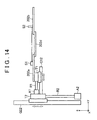
- FIG. 14 is a side view of the shape determining member 202 according to the second example embodiment.
- the xyz coordinates in FIGS. 13 and 14 also match those in FIG. 1 .
- the shape determining member 102 according to the first example embodiment shown in FIG. 2 is formed from one plate, so the thickness t1 and width w1 of the molten metal passage portion 103 are fixed.
- the shape determining member 202 according to the second example embodiment includes four rectangular shape determining plates 202 a, 202 b, 202 c, and 202 d, as shown in FIG. 13 . That is, the shape determining member 202 according to the second example embodiment is divided into a plurality of sections. This kind of structure enables the thickness t1 and width w1 of the molten metal passage portion 203 to be changed.
- the four rectangular shape determining plates 202 a, 202 b, 202 c, and 202 d are able to be synchronously moved in the z-axis direction.
- the pattern P is applied to the upper surface of the shape determining member 202 , similar to the shape determining member 102 .
- the shape determining plates 202 a and 202 b are arranged facing each other lined up in the y-axis direction. Also, as shown in FIG. 14 , the shape determining plates 202 a and 202 b are arranged at the same height in the z-axis direction. The distance between the shape determining plates 202 a and 202 b determines the width w1 of the molten metal passage portion 203 .
- the shape determining plates 202 a and 202 b are able to move independently in the y-axis direction, so they are able to change the width w1.
- a laser displacement gauge S 1 may be provided on the shape determining plate 202 a, and a laser reflecting plate S 2 may be provided on the shape determining plate 202 b, as shown in FIGS. 13 and 14 , in order to measure the width w1 of the molten metal passage portion 203 .
- the shape determining plates 202 c and 202 d are arranged facing each other lined up in the x-axis direction. Also, the shape determining plates 202 c and 202 d are arranged at the same height in the z-axis direction. The distance between the shape determining plates 202 c and 202 d determines the thickness t1 of the molten metal passage portion 203 . Also, the shape determining plates 202 c and 202 d are able to move independently in the x-axis direction, so they are able to change the thickness t1.
- the shape determining plates 202 a and 202 b are arranged contacting upper sides of the shape determining plates 202 c and 202 d.
- the drive mechanism of the shape determining plate 202 a will be described with reference to FIGS. 13 and 14 .
- the drive mechanism of the shape determining plate 202 a includes slide tables T 1 and T 2 , linear guides G 11 , G 12 , G 21 , and G 22 , actuators A 1 and A 2 , and rods R 1 and R 2 .
- the shape determining plates 202 b, 202 c, and 202 d also each include a drive mechanism, similar to the shape determining plate 202 a, but these are not shown in FIGS. 13 and 14 .
- the shape determining plate 202 a is placed on and fixed to the slide table T 1 that is able to slide in the y-axis direction.
- the slide table T 1 is slidably placed on the pair of linear guides G 11 and G 12 that extend parallel to the y-axis direction.
- the slide table T 1 is connected to the rod R 1 that extends in the y-axis direction from the actuator A 1 . This kind of structure enables the shape determining plate 202 a to slide in the y-axis direction.
- the linear guides 11 and 12 , and the actuator A 1 are placed on and fixed to the slide table T 2 that is able to slide in the z-axis direction.
- the slide table T 2 is slidably placed on the pair of linear guides G 21 and G 22 that extend parallel to the z-axis direction.
- the slide table T 2 is connected to the rod R 2 that extends in the z-axis direction from the actuator A 2 .
- the linear guides G 21 and G 22 , and the actuator A 2 are fixed to a horizontal floor or base, not shown, or the like. This kind of structure enables the shape determining plate 202 a to slide in the z-axis direction.
- the actuators A 1 and A 2 may be hydraulic cylinders, air cylinders, or electric motors or the like, for example.
- FIG. 15 is a flowchart illustrating the solidification interface control method according to the second example embodiment.
- the steps up to step ST 4 are the same as those in the first example embodiment shown in FIG. 5 , so a detailed description of these steps will be omitted.
- the casting controlling portion 111 determines whether the dimensions (i.e., the thickness t and the width w) at the solidification interface determined by the image analyzing portion 110 are within the dimensional tolerance of the casting M 3 (step ST 11 ).
- the dimensions (i.e., the thickness t and the width w) at the solidification interface are obtained simultaneously when the image analyzing portion 110 determines the solidification interface. If the dimensions obtained from the image are not within the dimensional tolerance (i.e., NO in step ST 11 ), the thickness t1 and the width w1 of the molten metal passage portion 103 are changed (step ST 12 ). Then the casting controlling portion 111 determines whether casting is complete (step ST 5 ).
- step ST 11 If the dimensions are within the dimensional tolerance (i.e., YES in step ST 11 ), the process proceeds directly on to step ST 5 without changing the thickness t1 and the width t1 of the molten metal passage portion 103 . If casting is not complete (i.e., NO in step ST 5 ), the process returns to step ST 1 . On the other hand, if casting is complete (i.e., YES in step ST 5 ), control of the solidification interface ends.
- the other structure is the same as that in the first example embodiment, so a description thereof will be omitted.
- the pattern P is applied to the upper surface of the shape determining member 202 , an image of the pattern P that is reflected onto an area near the solidification interface is captured, and the solidification interface is determined from this image, similar to the first example embodiment. Because the pattern P is reflected onto the retained molten metal M 2 , the brightness of the surface of the retained molten metal M 2 greatly changes when the retained molten metal M 2 oscillates slightly. Therefore, the solidification interface is able to be determined even when the solidification interface is low and oscillation of the molten metal is small. As a result, even if the solidification interface is low, feedback control for keeping the solidification interface within the predetermined reference range is able to be performed, so the dimensional accuracy and surface quality of the casting are able to be improved.
- the thickness t1 and the width w1 of the molten metal passage portion 203 of the shape determining member 202 are able to be changed. Therefore, when determining the solidification interface from the image, the thickness t and the width w at the solidification interface are measured, and the thickness t1 and the width w1 of the molten metal passage portion 203 are changed if this measured value is not within the dimensional tolerance. That is, feedback control for keeping the dimensions of the casting within the dimensional tolerance is able to be performed. As a result, the dimensional accuracy of the casting is able to be improved even more.
Landscapes
- Engineering & Computer Science (AREA)
- Mechanical Engineering (AREA)
- Continuous Casting (AREA)
- Length Measuring Devices By Optical Means (AREA)
- Image Analysis (AREA)
Abstract
Description
Claims (8)
Applications Claiming Priority (2)
| Application Number | Priority Date | Filing Date | Title |
|---|---|---|---|
| JP2014-046046 | 2014-03-10 | ||
| JP2014046046A JP5915678B2 (en) | 2014-03-10 | 2014-03-10 | Pull-up type continuous casting apparatus and pull-up type continuous casting method |
Publications (2)
| Publication Number | Publication Date |
|---|---|
| US20150251245A1 US20150251245A1 (en) | 2015-09-10 |
| US9427797B2 true US9427797B2 (en) | 2016-08-30 |
Family
ID=54016435
Family Applications (1)
| Application Number | Title | Priority Date | Filing Date |
|---|---|---|---|
| US14/638,348 Expired - Fee Related US9427797B2 (en) | 2014-03-10 | 2015-03-04 | Up-drawing continuous casting apparatus and up-drawing continuous casting method |
Country Status (3)
| Country | Link |
|---|---|
| US (1) | US9427797B2 (en) |
| JP (1) | JP5915678B2 (en) |
| CN (1) | CN104907517B (en) |
Families Citing this family (3)
| Publication number | Priority date | Publication date | Assignee | Title |
|---|---|---|---|---|
| CN107790661B (en) * | 2016-08-30 | 2019-09-20 | 宝山钢铁股份有限公司 | An automatic early warning system and method for corner defects of continuous casting billet |
| CN117047054A (en) * | 2023-07-26 | 2023-11-14 | 河南科技大学 | Method for detecting shape of continuous casting solid-liquid interface |
| CN117900407B (en) * | 2023-12-28 | 2024-11-01 | 宝钢工程技术集团有限公司 | A method for fault diagnosis of secondary cooling system in continuous casting |
Citations (5)
| Publication number | Priority date | Publication date | Assignee | Title |
|---|---|---|---|---|
| JPS63199050A (en) | 1987-02-13 | 1988-08-17 | Natl Res Inst For Metals | Pull-up continuous casting method that does not use a mold and its equipment |
| JPH09248657A (en) | 1996-03-19 | 1997-09-22 | Toyota Motor Corp | Molding method and molding apparatus |
| JP2005324203A (en) | 2004-05-12 | 2005-11-24 | Toyota Motor Corp | Method for detecting solidification process of molten metal |
| JP2012061518A (en) | 2010-09-17 | 2012-03-29 | Toyota Central R&D Labs Inc | Free casting method, free casting apparatus, and casting |
| JP2014104467A (en) | 2012-11-22 | 2014-06-09 | Toyota Motor Corp | Draw-up type continuous casting apparatus, draw-up type continuous casting method and solidification interface detection device |
Family Cites Families (7)
| Publication number | Priority date | Publication date | Assignee | Title |
|---|---|---|---|---|
| US4415017A (en) * | 1981-06-26 | 1983-11-15 | Olin Corporation | Control of liquid-solid interface in electromagnetic casting |
| JPS60191640A (en) * | 1984-03-12 | 1985-09-30 | Nippon Light Metal Co Ltd | Ingot casting method in heated mold continuous casting method |
| JPH02205232A (en) * | 1989-02-01 | 1990-08-15 | Natl Res Inst For Metals | Continuous pulling casting method and its equipment |
| JPH02251341A (en) * | 1989-03-25 | 1990-10-09 | Kubota Ltd | Continuous pulling casting equipment |
| JPH10230347A (en) * | 1997-02-18 | 1998-09-02 | Nippon Light Metal Co Ltd | Updrawing continuous casting method and apparatus for obtaining purified ingot from molten aluminum |
| CN201776417U (en) * | 2010-07-16 | 2011-03-30 | 石家庄爱迪尔电气有限公司 | Electromagnetic upper-leading suspension continuous casting device |
| CN203170937U (en) * | 2012-10-25 | 2013-09-04 | 苏州金江铜业有限公司 | Up-casting device |
-
2014
- 2014-03-10 JP JP2014046046A patent/JP5915678B2/en not_active Expired - Fee Related
-
2015
- 2015-03-04 US US14/638,348 patent/US9427797B2/en not_active Expired - Fee Related
- 2015-03-06 CN CN201510100369.4A patent/CN104907517B/en not_active Expired - Fee Related
Patent Citations (7)
| Publication number | Priority date | Publication date | Assignee | Title |
|---|---|---|---|---|
| JPS63199050A (en) | 1987-02-13 | 1988-08-17 | Natl Res Inst For Metals | Pull-up continuous casting method that does not use a mold and its equipment |
| JPH09248657A (en) | 1996-03-19 | 1997-09-22 | Toyota Motor Corp | Molding method and molding apparatus |
| US6217803B1 (en) | 1996-03-19 | 2001-04-17 | Toyota Jidosha Kabushiki Kaisha | Forming method and forming system |
| JP2005324203A (en) | 2004-05-12 | 2005-11-24 | Toyota Motor Corp | Method for detecting solidification process of molten metal |
| JP2012061518A (en) | 2010-09-17 | 2012-03-29 | Toyota Central R&D Labs Inc | Free casting method, free casting apparatus, and casting |
| US20130171021A1 (en) | 2010-09-17 | 2013-07-04 | Toyota Jidosha Kabushiki Kaisha | Free casting method, free casting apparatus, and casting |
| JP2014104467A (en) | 2012-11-22 | 2014-06-09 | Toyota Motor Corp | Draw-up type continuous casting apparatus, draw-up type continuous casting method and solidification interface detection device |
Also Published As
| Publication number | Publication date |
|---|---|
| CN104907517A (en) | 2015-09-16 |
| JP5915678B2 (en) | 2016-05-11 |
| US20150251245A1 (en) | 2015-09-10 |
| JP2015167988A (en) | 2015-09-28 |
| CN104907517B (en) | 2017-06-23 |
Similar Documents
| Publication | Publication Date | Title |
|---|---|---|
| US9427797B2 (en) | Up-drawing continuous casting apparatus and up-drawing continuous casting method | |
| US9931692B2 (en) | Hoisting type continuous casting device, hoisting type continuous casting method, and solidification interface detection device | |
| US9751127B2 (en) | Pulling-up-type continuous casting apparatus and pulling-up-type continuous casting method | |
| US9751128B2 (en) | Pulling-up-type continuous casting apparatus and pulling-up-type continuous casting method | |
| JP2021003813A (en) | Quality estimation device for additional product | |
| JP6036710B2 (en) | Pull-up continuous casting method and pull-up continuous casting apparatus | |
| US9919357B2 (en) | Up-drawing continuous casting apparatus and up-drawing continuous casting method | |
| US20150251243A1 (en) | Up-drawing continuous casting method | |
| US20150122451A1 (en) | Up-drawing continuous casting apparatus and up-drawing continuous casting method | |
| US10166600B2 (en) | Formed body manufacturing method and formed body manufacturing apparatus | |
| JP6003839B2 (en) | Pull-up continuous casting method and pull-up continuous casting apparatus | |
| JP2015027693A (en) | Drawing type continuous casting apparatus and drawing type continuous casting method | |
| KR101585786B1 (en) | Tundish gap control apparatus and method | |
| US20160296999A1 (en) | Pulling-up-type continuous casting method and pulling-up-type continuous casting apparatus |
Legal Events
| Date | Code | Title | Description |
|---|---|---|---|
| AS | Assignment |
Owner name: TOYOTA JIDOSHA KABUSHIKI KAISHA, JAPAN Free format text: ASSIGNMENT OF ASSIGNORS INTEREST;ASSIGNORS:SUGIURA, NAOAKI;TSUCHIYA, SHOICHI;YOKOTA, YUSUKE;SIGNING DATES FROM 20150113 TO 20150115;REEL/FRAME:035195/0816 |
|
| ZAAA | Notice of allowance and fees due |
Free format text: ORIGINAL CODE: NOA |
|
| ZAAB | Notice of allowance mailed |
Free format text: ORIGINAL CODE: MN/=. |
|
| STCF | Information on status: patent grant |
Free format text: PATENTED CASE |
|
| MAFP | Maintenance fee payment |
Free format text: PAYMENT OF MAINTENANCE FEE, 4TH YEAR, LARGE ENTITY (ORIGINAL EVENT CODE: M1551); ENTITY STATUS OF PATENT OWNER: LARGE ENTITY Year of fee payment: 4 |
|
| FEPP | Fee payment procedure |
Free format text: MAINTENANCE FEE REMINDER MAILED (ORIGINAL EVENT CODE: REM.); ENTITY STATUS OF PATENT OWNER: LARGE ENTITY |
|
| LAPS | Lapse for failure to pay maintenance fees |
Free format text: PATENT EXPIRED FOR FAILURE TO PAY MAINTENANCE FEES (ORIGINAL EVENT CODE: EXP.); ENTITY STATUS OF PATENT OWNER: LARGE ENTITY |
|
| STCH | Information on status: patent discontinuation |
Free format text: PATENT EXPIRED DUE TO NONPAYMENT OF MAINTENANCE FEES UNDER 37 CFR 1.362 |
|
| FP | Lapsed due to failure to pay maintenance fee |
Effective date: 20240830 |