US9426564B2 - Audio processing device, method and program - Google Patents
Audio processing device, method and program Download PDFInfo
- Publication number
- US9426564B2 US9426564B2 US14/072,050 US201314072050A US9426564B2 US 9426564 B2 US9426564 B2 US 9426564B2 US 201314072050 A US201314072050 A US 201314072050A US 9426564 B2 US9426564 B2 US 9426564B2
- Authority
- US
- United States
- Prior art keywords
- frequency
- matrix
- time
- channel
- audio
- Prior art date
- Legal status (The legal status is an assumption and is not a legal conclusion. Google has not performed a legal analysis and makes no representation as to the accuracy of the status listed.)
- Expired - Fee Related, expires
Links
Images

Classifications
-
- H—ELECTRICITY
- H04—ELECTRIC COMMUNICATION TECHNIQUE
- H04R—LOUDSPEAKERS, MICROPHONES, GRAMOPHONE PICK-UPS OR LIKE ACOUSTIC ELECTROMECHANICAL TRANSDUCERS; DEAF-AID SETS; PUBLIC ADDRESS SYSTEMS
- H04R3/00—Circuits for transducers, loudspeakers or microphones
-
- H—ELECTRICITY
- H04—ELECTRIC COMMUNICATION TECHNIQUE
- H04S—STEREOPHONIC SYSTEMS
- H04S7/00—Indicating arrangements; Control arrangements, e.g. balance control
- H04S7/30—Control circuits for electronic adaptation of the sound field
- H04S7/302—Electronic adaptation of stereophonic sound system to listener position or orientation
-
- G—PHYSICS
- G06—COMPUTING OR CALCULATING; COUNTING
- G06F—ELECTRIC DIGITAL DATA PROCESSING
- G06F16/00—Information retrieval; Database structures therefor; File system structures therefor
- G06F16/20—Information retrieval; Database structures therefor; File system structures therefor of structured data, e.g. relational data
- G06F16/28—Databases characterised by their database models, e.g. relational or object models
- G06F16/283—Multi-dimensional databases or data warehouses, e.g. MOLAP or ROLAP
-
- G06F17/30592—
-
- G—PHYSICS
- G10—MUSICAL INSTRUMENTS; ACOUSTICS
- G10L—SPEECH ANALYSIS TECHNIQUES OR SPEECH SYNTHESIS; SPEECH RECOGNITION; SPEECH OR VOICE PROCESSING TECHNIQUES; SPEECH OR AUDIO CODING OR DECODING
- G10L21/00—Speech or voice signal processing techniques to produce another audible or non-audible signal, e.g. visual or tactile, in order to modify its quality or its intelligibility
- G10L21/02—Speech enhancement, e.g. noise reduction or echo cancellation
- G10L21/0208—Noise filtering
- G10L21/0216—Noise filtering characterised by the method used for estimating noise
- G10L2021/02161—Number of inputs available containing the signal or the noise to be suppressed
- G10L2021/02166—Microphone arrays; Beamforming
-
- G—PHYSICS
- G10—MUSICAL INSTRUMENTS; ACOUSTICS
- G10L—SPEECH ANALYSIS TECHNIQUES OR SPEECH SYNTHESIS; SPEECH RECOGNITION; SPEECH OR VOICE PROCESSING TECHNIQUES; SPEECH OR AUDIO CODING OR DECODING
- G10L21/00—Speech or voice signal processing techniques to produce another audible or non-audible signal, e.g. visual or tactile, in order to modify its quality or its intelligibility
- G10L21/02—Speech enhancement, e.g. noise reduction or echo cancellation
- G10L21/0208—Noise filtering
-
- H—ELECTRICITY
- H04—ELECTRIC COMMUNICATION TECHNIQUE
- H04R—LOUDSPEAKERS, MICROPHONES, GRAMOPHONE PICK-UPS OR LIKE ACOUSTIC ELECTROMECHANICAL TRANSDUCERS; DEAF-AID SETS; PUBLIC ADDRESS SYSTEMS
- H04R1/00—Details of transducers, loudspeakers or microphones
- H04R1/02—Casings; Cabinets ; Supports therefor; Mountings therein
- H04R1/028—Casings; Cabinets ; Supports therefor; Mountings therein associated with devices performing functions other than acoustics, e.g. electric candles
-
- H—ELECTRICITY
- H04—ELECTRIC COMMUNICATION TECHNIQUE
- H04S—STEREOPHONIC SYSTEMS
- H04S2400/00—Details of stereophonic systems covered by H04S but not provided for in its groups
- H04S2400/15—Aspects of sound capture and related signal processing for recording or reproduction
Definitions
- the present technology relates to an audio processing device, method and program, in particular to an audio processing device, method and program which are able to more easily extract audio from a sound source in a desired direction.
- a technology of the related art may separate the audio output from a plurality of sound sources into audio of the respective sound sources.
- a method has been proposed which realizes high sound source separation ability even in environments having noise influence by separating one or more sound source signals from a plurality of mixed audio signals and further subjecting them to a binary masking process using sound source separation processing based on the independent component analysis method (for example, refer to Japanese Unexamined Patent Application Publication No. 2006-154314).
- An audio processing device includes a factorization unit which factorizes frequency information obtained by performing time-frequency transformation on an audio signal from a plurality of channels into a channel matrix representing characteristics of a channel direction, a frequency matrix representing characteristics of a frequency direction, and a time matrix representing characteristics of a time direction; and an extraction unit which extracts the frequency information of audio from an arbitrary designated direction based on the channel matrix, the frequency matrix, and the time matrix.
- the audio processing device may further include a direction specification unit which obtains direction specification information specifying a matrix component relating to audio from the designated direction based on direction information and the channel matrix representing the designated direction; in which the extraction unit extracts the frequency information of audio from the designated direction based on the channel matrix, the frequency matrix, as well as the time matrix and the direction specification information.
- a direction specification unit which obtains direction specification information specifying a matrix component relating to audio from the designated direction based on direction information and the channel matrix representing the designated direction; in which the extraction unit extracts the frequency information of audio from the designated direction based on the channel matrix, the frequency matrix, as well as the time matrix and the direction specification information.
- the extraction unit may extract the frequency information of audio from the designated direction by amplifying the frequency information by an amplification factor determined using the direction specification information.
- the extraction unit may change the amplification factor based on statistical characteristics of the frequency matrix or the time matrix.
- the factorization unit assumes that the frequency information is a three-dimensional tensor where a channel, a frequency, and a time frame are the respective dimensions, and may factorize the frequency information into the channel matrix, the frequency matrix, and the time matrix by performing tensor factorization.
- the tensor factorization may be a non-negative tensor factorization.
- the audio processing device may further include a frequency-time transform unit which generates an audio signal from a plurality of channels by performing frequency-time transformation on the frequency information of audio from the designated direction obtained by the extraction unit.
- an audio processing method or program including factorizing frequency information obtained by performing time-frequency transformation on an audio signal from a plurality of channels into a channel matrix representing characteristics of a channel direction, a frequency matrix representing characteristics of a frequency direction, and a time matrix representing characteristics of a time direction; and extracting the frequency information of audio from an arbitrary designated direction based on the channel matrix, the frequency matrix, and the time matrix.
- frequency information obtained by performing time-frequency transformation on an audio signal from a plurality of channels is factorized into a channel matrix representing characteristics of a channel direction, a frequency matrix representing characteristics of a frequency direction, and a time matrix representing characteristics of a time direction; and the frequency information of audio from an arbitrary designated direction based on the channel matrix, the frequency matrix, and the time matrix is extracted.
- FIG. 1 is a view showing an example of the configuration of the appearance of a spectacle-type apparatus
- FIG. 2 is a view showing an example of the configuration of a direction designated audio amplifier
- FIG. 3 is a view illustrating an input complex spectrum
- FIG. 4 is a view illustrating an input complex spectrogram
- FIG. 5 is a view illustrating a tensor factorization
- FIG. 6 is a view illustrating a channel matrix
- FIG. 7 is a view illustrating the specification of the designated direction
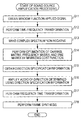
- FIG. 8 is a flowchart illustrating the sound source amplification processing
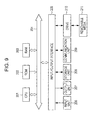
- FIG. 9 is a view showing an example of the configuration of a computer.
- the present technology relates to a direction designated sound source extraction device which extracts audio from a sound source in a desired direction from the audio from a plurality of sound sources.
- the direction designated audio amplifier provided in an inner portion of the spectacle-type apparatus as an example of the direction designated sound source extraction device.
- the direction designated audio amplifier is realized using an application program which amplifies only the audio of an arbitrary direction which a user designates. Furthermore, attenuation of the audio is realized by a negative amplification factor.
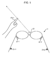
- FIG. 1 The appearance of a spectacle-type apparatus with a built-in direction designated audio amplifier is configured, for example, as shown in FIG. 1 .
- a spectacle-type apparatus 11 there is provided a spectacle-type apparatus 11 , a camera 21 , a microphone 22 - 1 , a microphone 22 - 2 , an earphone 23 - 1 , and an earphone 23 - 2 .
- the camera 21 is provided in the center of the spectacles, and the left channel microphone 22 - 1 and the right channel microphone 22 - 2 are provided respectively in the vicinity of the left and right lenses.
- the left channel earphone 23 - 1 and the right channel earphone 23 - 2 are provided respectively on the left and right temple portions of the spectacle-type apparatus 11 .
- the microphones 22 when there is no particular reason to distinguish between the microphone 22 - 1 and the microphone 22 - 2 , they will simply be referred to as the microphones 22 , and when there is no particular reason to distinguish between the earphone 23 - 1 and the earphone 23 - 2 , they will simply be referred to as the earphones 23 .
- the microphones 22 there are a total of two of the microphones 22 provided in the spectacle-type apparatus 11 , however, three or more microphones 22 may also be provided. Similarly, three or more of the earphones 23 may also be provided.
- peripheral audio is collected by the monaural microphones 22 provided on the left and right, the audio signal obtained thereby is submitted to acoustic treatment, and the audio of a direction designated by the user is amplified. Furthermore, the audio signal which has been amplification processed is supplied to the earphones 23 , and audio is output from the earphones 23 .
- the user when designating the direction of the audio to amplify, for example, the user holds out the index finger FG 11 of their left hand and designates the sound source direction of the audio to be extracted.
- the spectacle-type apparatus 11 Since the camera 21 provided in the center of the spectacles of the spectacle-type apparatus 11 images the image in front of the user wearing the spectacle-type apparatus 11 , the index finger FG 11 appears on the image imaged by the camera 21 . Then, the spectacle-type apparatus 11 detects the index finger FG 11 from the image imaged by the camera 21 and specifies the direction designated by the user, based on the detection results. In the spectacle-type apparatus 11 , only the audio from the direction which is specified in this manner is amplified and reproduced.
- the detection of the index finger FG 11 on the image is performed by, for example, object detection using feature values, or the like, however, the specification method of a direction designated by the user may be any manner of method.
- the designated direction may be specified by the user wearing a predetermined finger stall on the index finger FG 11 and the finger stall being detected, and may also be specified by the user directly inputting the direction to designate.
- an application program which amplifies only the audio of the direction designated by the user will be described, however, the present technology may also be applied to, for example, musical instrument extraction, sound source separation with facial recognition, and the like.
- musical instrument extraction is an application program which designates a specific musical instrument in a situation in which musical instrument map information showing the three-dimensional arrangement of musical instruments beforehand may be obtained, and extracts the audio signal of only a specific musical instrument using sound source separation with prior information.
- sound source separation with facial recognition is an application program which specifies the direction in which a plurality of humans are present using facial recognition, and separates the voices of each human using the directional information and the general characteristics of the human voice.
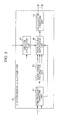
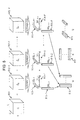
- FIG. 2 is a view showing an example of the configuration of a direction designated audio amplifier.
- the direction designated audio amplifier 51 is formed from a time-frequency transform unit 61 , a sound source factorization unit 62 , a direction specification unit 63 , a sound source amplification unit 64 , and a frequency-time transform unit 65 .
- the audio signal of a plurality of channels collected by the microphones 22 is supplied as a multichannel input signal.
- the time-frequency transform unit 61 performs time-frequency transformation on the supplied multichannel input signal and supplies the input complex spectrum which was obtained as a result to the sound source amplification unit 64 , in addition to supplying a non-negative spectrogram, formed from a non-negative spectrum obtained by making an input complex spectrum non-negative, to the sound source factorization unit 62 .
- the sound source factorization unit 62 assumes that the non-negative spectrogram supplied from the time-frequency transform unit 61 is a three-dimensional tensor, in which the dimensions are the channel, the frequency, and the time frame, and performs Non-negative Tensor Factorization (NTF).
- NTF Non-negative Tensor Factorization
- the sound source factorization unit 62 supplies the channel matrix Q, the frequency matrix W, and the time matrix H obtained using the non-negative tensor factorization to the sound source amplification unit 64 , in addition to supplying the channel matrix Q to the direction specification unit 63 .
- the directional information u which shows the direction which was designated by the user and obtained based on the image imaged by the camera 21 , in other words, the direction of the sound source to be amplified (hereinafter also referred to as the designated direction), is supplied to the direction specification unit 63 .
- the direction specification unit 63 Based on the supplied direction information u and the channel matrix Q from the sound source factorization unit 62 , the direction specification unit 63 obtains the direction specification information q, which specifies a matrix component relating to the audio, from the designated direction which is contained in the matrix obtained from the non-negative spectrum and supplies the direction specification information q to the sound source amplification unit 64 .
- the sound source amplification unit 64 Based on the input complex spectrum from the time-frequency transform unit 61 , the channel matrix Q from the sound source factorization unit 62 , the frequency matrix W, and the time matrix H, as well as the direction specification information q from the direction specification unit 63 , the sound source amplification unit 64 generates an output time-frequency spectrum in which the audio from the designated direction is amplified and supplies the output time-frequency spectrum to the frequency-time transform unit 65 .
- the factorized tensor component specified by the direction specification information q is selected, an amplification factor corresponding to the selection result is multiplied by each tensor component, and amplification of the amplitude of the audio component from a designated direction on the spectrogram is performed.
- the frequency-time transform unit 65 generates an amplified multichannel output signal and outputs the amplified multichannel output signal to the earphones 23 by performing an Overlap-Add on the obtained time signal after performing frequency-time transformation on the output time-frequency spectrum supplied from the sound source amplification unit 64 .
- the time-frequency transform unit 61 analyses the time-frequency information of the multichannel input signal x(c, t) supplied from the microphones 22 .
- the time-frequency transform unit 61 performs time frame division of a static size on the multichannel input signal x(c, t), multiplies the multichannel frame signal x′(c, n, l) which was obtained as a result with a window function W ana (n), and obtains a window function applied signal wx(c, n, l).
- c and t in the multichannel input signal x(c, t) refer to the channel index and the time, respectively.
- c, n, and l in the multichannel frame signal x′(c, n, l), and the window function applied signal wx(c, n, l) refer to the channel index, the time index, and the time frame index, respectively.
- C is the total number of channels
- N is the frame size, in other words, the number of samples within one frame
- L is the total number of time frames.
- the time-frequency transform unit 61 calculates the window function applied signal wx(c, n, l) from the multichannel frame signal x′(c, n, l) by performing the calculation of the following Expression (1).
- wx ( c,n,l ) W ana ( n ) ⁇ x ′( c,n,l ) (1)
- window function w ana (n) used in the operation of Expression (1) is, for example, a function such as that shown in the following Expression (2).
- window function w ana (n) is the square root of a Hanning window, however other windows such as the Hanning window or the Blackman Harris window may also be used as the window function.
- r( ) is an arbitrary rounding function, and here, for example, is the maximal rounding system.
- the shift amount of the frame is not limited to 50% of the frame size N, and may be any value.
- the time-frequency transform unit 61 performs time-frequency transformation on the window function applied signal wx(c, n, l) and obtains an input complex spectrum X(c, k, l).
- the calculation of the following Expression (3) is performed, and the input complex spectrum X(c, k, l) is calculated using a discrete Fourier transform (DFT).
- DFT discrete Fourier transform
- j represents a purely imaginary number
- M represents the number of points used in the time-frequency transformation.
- the number of points M is the frame size N or greater, and is a value such as an exponent of 2 which is closest to N, however, may also be another number.
- K M/2+1.
- wx′(c, m, l) is a zero-padded signal and is represented by the following Expression (4).
- the zero-padding is performed corresponding to the number of points M of the discrete Fourier transform according to necessity.
- DCT discrete cosine transform
- MDCT modified discrete cosine transform
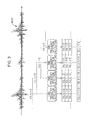
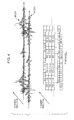
- the time-frequency transform unit 61 calculates the input complex spectrum X(c, k, l) by performing time-frequency transformation for each time frame of the multichannel input signal x(c, t), the time-frequency transform unit 61 concatenates the input complex spectra X(c, k, l) which span a plurality of frames of the same channel, and configures a matrix.
- the matrix shown in FIG. 3 is obtained.
- time-frequency transformation is being performed in relation to the four multichannel frame signals, multichannel frame signal x′(c, n, l ⁇ 3) to multichannel frame signal x′(c, n, l) which are adjacent to each other in the multichannel input signal x(c, t) of one channel represented by the arrow MCS 11 .
- the vertical direction and horizontal direction of the multichannel input signal x(c, t) represented by the arrow MCS 11 represent the amplitude and the time, respectively.
- one rectangle represents one input complex spectrum, for example, K input complex spectra, input complex spectrum X(c, 0, 1-3) to input complex spectrum X(c, K ⁇ 1, l ⁇ 3), are obtained using time-frequency transformation in relation to the multichannel frame signal x′(c, n, l ⁇ 3).
- the input complex spectra are concatenated into a single matrix. Furthermore, the input complex spectrogram X shown in FIG. 4 is obtained by further concatenating the matrices obtained for each of C channels.
- FIG. 4 the same reference numerals will be given to portions corresponding to those in the case of FIG. 3 , and a description thereof will be omitted.
- each input complex spectrum in the figure is arranged and concatenated in the vertical direction, the horizontal direction, and the depth direction, in other words, in the frequency direction, the time direction, and the channel direction to form an input complex spectrogram X in a three-dimensional tensor representation.
- the time-frequency transform unit 61 calculates a non-negative spectrum G(c, k, l) by performing the calculation of the following Expression (5) and making each of the input complex spectra X(c, k, l), which were obtained using time-frequency transformation, non-negative.
- G ( c,k,l ) ( X ( c,k,l ) ⁇ conj( X ( c,k,l ))) ⁇ (5)
- conj(X(c, k, l)) represents a complex conjugate of the input complex spectrum X(c, k, l), and ⁇ represents a non-negative control value.
- the non-negative spectra G(c, k, l) obtained using the calculation of Expression (5) are conjugated in the channel direction, the frequency direction and the time frame direction, are the non-negative spectrogram G which is supplied from the time-frequency transform unit 61 to the sound source factorization unit 62 .
- the sound source factorization unit 62 treats the non-negative spectrogram G as a three-dimensional tensor of C ⁇ K ⁇ L, and separates the non-negative spectrogram G into P three-dimensional tensors ⁇ P (hereinafter, referred to as the base spectrogram).
- the P base spectrograms ⁇ p may express the outer product of three vectors, they are respectively factorized into three vectors. Accordingly, as a result of collecting P vectors of each of the three types, three new matrices, in other words, the channel matrix Q, the frequency matrix W, and the time matrix H, may be obtained, therefore the non-negative spectrogram G could be said to be possible to factorize into three matrices. Furthermore, the size of the channel matrix Q is C ⁇ P, the size of the frequency matrix W is K ⁇ P, and the size of the time matrix H is L ⁇ P.
- the tensor factorization is performed by minimizing the error tensor E using non-negative tensor factorization.
- the necessary constraints for optimization are that there is non-negativity between the non-negative spectrogram G, the channel matrix Q, the frequency matrix W, and the time matrix H.
- non-negative tensor factorization unlike in tensor factorization methods of the related art such as PARAFAC or Tucker factorization, it is possible to extract the inherent characteristics which the sound source has.
- non-negative tensor factorization is also a generalization of the tensor of a Non-negative Matrix Factorization (NMF).
- NMF Non-negative Matrix Factorization
- the channel matrix Q, the frequency matrix W, and the time matrix H obtained using tensor factorization each have inherent characteristics.
- the base spectrogram ⁇ 0 to the base spectrogram ⁇ P-1 represented by the arrow R 12 - 1 to the arrow R 12 -P are obtained.
- Each of the base spectrograms ⁇ P (where 0 ⁇ p ⁇ P ⁇ 1), in other words, the three-dimensional tensor ⁇ P described above, may respectively be represented by an outer product of the three vectors.
- the base spectrogram ⁇ 0 may be represented by the outer product of the three vectors of, the vector [Q] c,0 represented by the arrow R 13 - 1 , the vector [H] l,0 represented by the arrow R 14 - 1 , and the vector [W] k,0 represented by the arrow R 15 - 1 .
- the vector [Q] c,0 is a column vector formed from a total number of channels C elements, and the sum of the values of each of the C elements is 1.
- Each of the C elements of the vector [Q] c,0 is a component which corresponds to each channel represented by the channel index c.
- the vector [H] l,0 is a row vector formed from a total number of time frames L elements, and each of the L elements of the vector [H] l,0 is a component which corresponds to each time frame represented by the time frame index l. Furthermore, the vector [W] k,0 is a column vector formed from a number of frequency K elements, and each of the K elements of the vector [W] k,0 is a component which corresponds to the frequency represented by the frequency index k.
- the vector [Q] c,0 , the vector [H] l,0 , and the vector represent the characteristics of the channel direction of the base spectrogram ⁇ 0 , the characteristics of the time direction, and the characteristics of the frequency direction, respectively.
- the base spectrogram ⁇ 1 may be represented by the outer product of the three vectors of, the vector [Q] c,1 represented by the arrow R 13 - 2 , the vector [H] l,1 represented by the arrow R 14 - 2 , and the vector [W] k,1 represented by the arrow R 15 - 2 .
- the base spectrogram may be represented by the outer product of the three vectors of, the vector [Q] c,P-1 represented by the arrow R 13 -P, the vector [H] l,P-1 represented by the arrow R 14 -P, and the vector [W] k,P-1 represented by the arrow R 15 -P.
- the channel matrix Q, the frequency matrix W, and the time matrix H are the result of collecting, for each respective dimension, the three vectors which correspond to the three dimensions of the P base spectrograms ⁇ p (where 0 ⁇ p ⁇ P) and making them into a matrix.
- the matrix formed from the vector [W] k,0 to the vector [W] k,P-1 , which are vectors which represent the characteristics of the frequency direction of each base spectrogram ⁇ p , is the frequency matrix W.
- the matrix formed from the vector [H] l,0 to the vector [H] l,P-1 , which are vectors which represent the characteristics of the time direction of each base spectrogram ⁇ p is the time matrix H.
- the matrix formed from the vector [Q] c,0 to the vector [Q] c,P-1 , which are vectors which represent the characteristics of the channel direction of each base spectrogram ⁇ p is the channel matrix Q.
- each base spectrogram ⁇ p which is factorized into P, represents an inherent characteristic within the sound source, respectively.
- NTF Non-negative Tensor Factorization
- the audio from the point sound source AS 1 is the audio of a person
- the audio from the point sound source AS 2 is the engine noise of a vehicle.
- the two point sound sources have a tendency to be exhibited in different base spectrograms ⁇ p , respectively.
- r base spectrograms ⁇ p which are arranged continuously are allocated to the sound of a person which is the first point sound source AS 1
- P-r base spectrograms ⁇ p which are arranged continuously are allocated to the engine noise of a vehicle which is the second point sound source AS 2 .
- each matrix the channel matrix Q, the frequency matrix W, and the time matrix H.
- the channel matrix Q represents the characteristics of the channel direction of the non-negative spectrogram G.
- the channel matrix Q is considered to represent the degree of contribution of each of the P base spectrograms ⁇ p to each of the total of C channels c.
- the value of the left channel and the value of the right channel are both 0.5.
- the value of the left channel is 0.9, and the value of the right channel is 0.1.
- the values of the components of the left and right channels of the element [Q] :,0 are the same, therefore, since the same weight is applied to both the left and right channels, the sound source represented by the base spectrogram ⁇ 0 is present at equal distances in relation to the channels.
- the channel matrix Q represents the arrangement information of each point sound source.
- each element of the channel matrix Q is shown in FIG. 6 .
- the vertical axis and the horizontal axis represent the components of the channel 1 and the channel 2 .
- channel 1 is the left channel and channel 2 is the right channel.
- the vector VC 11 to the vector VC 17 are the element [Q] c,0 to the elemen t[Q] c,6 , respectively, and the element [Q] c,0 to the element [Q] c,6 are arranged at equal distances.
- the value of the element [Q] c,3 is [0.5, 0.5] T
- the element [Q] c,3 represents the direction centrally between the axial direction of the channel 1 and the axial direction of the channel 2 .
- the direction of the point sound source of the target audio is the central direction of the space in which the axial direction is the channel 1 direction and the channel 2 direction
- the frequency matrix W represents the characteristics of the frequency direction of the non-negative spectrogram G. More specifically, the frequency matrix W represents the degree of contribution of each of the total of P base spectrograms ⁇ p to each of the K frequency bins, in other words, it represents each of the frequency characteristics of each base spectrogram ⁇ p .
- the base spectrogram ⁇ p which represents the vowels of the audio has a matrix element [W] :,p which represents frequency characteristics in which the low-pass is emphasized
- the base spectrogram ⁇ p which represents an affricate consonant has an element [W] :,p which represents frequency characteristics in which the high-pass is emphasized.
- the time matrix H represents the characteristics of the time direction of the non-negative spectrogram G. More specifically, the time matrix H represents the degree of contribution of each of the P base spectrograms ⁇ p to each of the total of L time frames, in other words, it represents each of the time characteristics of each base spectrogram ⁇ p .
- the base spectrogram ⁇ p which represents the stationary environmental noise has a matrix element which represents the time characteristics in which the components of each time frame index l have equal values.
- the base spectrogram ⁇ p represents the non-stationary environmental noise
- the base spectrogram ⁇ p has a matrix element [H] :,p which represents the time characteristics which momentarily have a large value, in other words, it has a matrix element [H] :,p in which the component of a specific time frame index l is a large value.
- NTF Non-negative Tensor Factorization
- S(W) and T(H) are respectively the constraint functions of the cost functions C, in which the input thereof is the frequency matrix W and the time matrix H.
- ⁇ and ⁇ respectively represent the weight of the constraint function S(W) of the frequency matrix W, and the weight of the constraint function T(H) of the time matrix H.
- the addition of the constraint function has an effect of constraining the cost function, and affects the manner in which separation occurs. Generally, sparse constraints, smooth constraints, and the like are often used.
- g ckl represents the element of the non-negative spectrogram G
- ⁇ ckl is a predictive value of the element g ckl .
- This element a ⁇ ckl is obtained using the following Expression (7).
- q cp is an element specified using the channel index c and the base index p which configure the channel matrix Q, in other words, is the matrix element [Q] c,p .
- w kp is the matrix element [W] k,p
- h lp is the matrix element [H] l,p .
- ⁇ divergence d ⁇ is used as an index for measuring the distance between the non-negative spectrogram G and the approximate spectrogram G, and this ⁇ divergence is represented by, for example, the following Expression (8).
- the approximate spectrogram ⁇ is the approximate value of the non-negative spectrogram G, which is obtained from the base number P of the base spectrograms ⁇ p .
- ⁇ ) in the example of Expression (6) is as shown in the following Expression (11).
- the partial differentials in relation to the channel matrix Q, the frequency matrix W, and the time matrix H are respectively as shown in the following Expression (12) to Expression (14), where in Expression (11) to Expression (14), subtraction, division, and logarithmic arithmetic are all calculated per element.
- NTF Non-negative Tensor Factorization
- Expression (16) to Expression (18) “O” represents the outer product of the matrix.
- ⁇ A, B> C, D are referred to as the tensor contraction product and are represented by the following Expression (19), where in Expression (19), each character in the expression has no relation with the symbols which represent the matrices and the like which have been described above.
- the constraint function S(W) of the frequency matrix W, and the constraint function T(H) of the time matrix H are considered, and the respective degree of influence on the cost functions C thereof is controlled by the weights ⁇ and ⁇ .
- a constraint function T(H) is added such that components which have a similar base index p of the time matrix H have a strong correlation to one another, and components which have a dissimilar base index p have a weak correlation to one another. This is because it is desirable to consolidate the direction of the base spectrogram ⁇ p of sound sources of the same characteristics into a specific direction as much as possible when one of the point sound sources is factorized into several base spectrograms ⁇ p .
- the penalty control values may also be other values.
- the constraint function S(W), the constraint function T(H), the function ⁇ W S(W), and the function ⁇ H T(H) are respectively the functions shown in the following Expression (20) to Expression (23).
- S ( W ) 0 (20)
- T ( H )
- Expression (21) the symbol “ ⁇ ” represents the multiplication of elements with one another
- Expression (21) and Expression (23) B represents a correlation control matrix, in which the size is P ⁇ P.
- the diagonal component of the correlation control matrix B is 0, as the value of the off-diagonal component of the correlation control matrix B becomes further from that of the diagonal component, the value linearly approaches 1.
- initialization is performed so as to maintain an equal distance between each adjacent element of the channel matrix Q.
- element [Q] :,0 [0.0, 1.0] T
- element [Q] :,1 [0.5, 0.5] T
- element [Q] :,2 [1.0, 0.0] T , and the like.
- extra elements [Q] :,p are allocated in the direction which indicates the direction specification information q which is subsequently determined.
- initialization of the channel matrix Q is performed so as to maintain an equal distance between each adjacent element, however, the values of elements may also be the same as one another, or be arranged arbitrarily.
- initialization is performed using a random non-negative value, however, a user may also designate an arbitrary value.
- the sound source factorization unit 62 obtains the optimized channel matrix Q, frequency matrix W, and time matrix H.
- the channel matrix Q is supplied to the direction specification unit 63 from the sound source factorization unit 62 . Furthermore, in addition to the obtained channel matrix Q being supplied to the direction specification unit 63 from the sound source factorization unit 62 , the channel matrix Q, the frequency matrix W, and the time matrix H are supplied from the sound source factorization unit 62 to the sound source amplification unit 64 .
- the direction of the sound source to be amplified in a space, in which the axial directions are the respective channel directions, is specified based on the supplied direction information u corresponding to the designated direction, which is designated by the user, and the channel matrix Q, which is supplied from the sound source factorization unit 62 .
- the direction specification information q is obtained.
- the direction information u is provided in an equivalent format to the element [Q] :,p of the channel matrix Q, in the form of a weight to each channel, however, the format of the direction information u may also be another format.
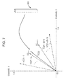
- the direction specification unit 63 calculates the direction specification information q by calculating the following Expression (26) based on the direction information u and the element [Q] :,p of the channel matrix Q.
- the vertical axis and the horizontal axis represent the components of the channel 1 and the channel 2 .
- channel 1 is the left channel and channel 2 is the right channel.
- the vector VC 21 - 1 to the vector VC 21 -(P ⁇ 1) represented by arrows represent the vector [Q] c,0 to the vector [Q] c,P-1
- the vector VC 22 represented by the arrow represents a vector represented by the direction information u.
- the vectors VC 21 when there is no particular reason to distinguish between the vector VC 21 - 1 and the vector VC 21 -(P ⁇ 1), they will simply be referred to as the vectors VC 21 .
- the direction information u represented by the arrow R 41 is supplied to the direction specification unit 63 , the direction information u is projected onto space, in which each channel direction is the axial direction, and is set as the vector VC 22 . Furthermore, the distance between each vector VC 21 and the vector VC 22 is compared and the direction specification information q is obtained.
- the distance from the vector VC 22 is minimum when the vector VC 21 - q .
- the direction specification information q obtained in this manner is supplied from the direction specification unit 63 to the sound source amplification unit 64 .
- the distance of each element [Q] :,p of the channel matrix Q and the direction information u is not limited to the square distance and may also be another distance.
- the direction specification information q may also be calculated by obtaining the degree of approximation with the direction information u using an approximation degree calculation.
- the sound source amplification unit 64 amplification of the positive of the signal of the designated direction and the adjacent directions thereof, and amplification of the negative of the signal of other directions is performed based on the channel matrix Q, the frequency matrix W, and the time matrix H supplied from the sound source factorization unit 62 , the direction specification information q supplied from the direction specification unit 63 , and the input complex spectrogram X supplied from the time-frequency transform unit 61 .
- the sound source amplification unit 64 obtains an output complex spectrogram Y in which the output time-frequency spectrum Y(c, k, l) is expressed as a three-dimensional tensor by performing the calculation of the following expression (27).
- the output complex spectrogram Y is obtained by concatenating the output time-frequency spectrum Y(c, k, l) into the channel direction, the time frame direction, and the frequency direction.
- the input complex spectrogram X is also obtained by expressing the input complex spectrum X(c, k, l) as a three-dimensional tensor.
- the symbol “ ⁇ ” represents multiplication of the elements with one another.
- the element A p is a tensor formed from elements relating to the base index p of a four-dimensional amplification factor tensor A of C ⁇ K ⁇ L ⁇ P.
- the value of a tensor formed from elements relating to the time frame index l and the base index p of the amplification factor tensor A will also be referred to as the value of the amplification factor tensor [A] :,:,l,p .
- each input complex spectrum X(c, k, l) is amplified according to the base index p.
- the base index p is a direction dissimilar to the direction specification information q, in other words, when the difference between the base index p and the direction specification information q is great, the value of the amplification factor tensor [A] :,:,l,p becomes smaller according to the passage of time.
- the value of the amplification factor tensor [A] :,:,0,q is +0 dB and the amplification factor tensor [A] :,:,l,q , may be supplemented such that the value of the amplification factor tensor [A] :,:,l,q is +4 dB, and may also be another value.
- the value of the amplification factor tensor [A] :,:,l,p may linearly decrease 1 dB at a time as the base index p becomes less similar to the direction specification information q, and may also be another value.
- only the desired sound source may be extracted by setting all of the elements of the amplification factor tensor [A] :,:,:,p which corresponds to the base index p thereof to 0.
- the sound source amplification unit 64 as shown in the following Expression (28), when the dispersion of the matrix element [H] :,p of the time matrix H is thre_H or less, the noise is assumed to be stationary and all of the elements of the amplification factor tensor [A] :,:,:,p are set to 0.
- set to thre_H 100.
- the sound source amplification unit 64 distinguishes sound sources present in the same direction using the statistical characteristics of the frequency matrix W or the time matrix H, and appropriately determines (changes) the values of the elements of the amplification factor tensor [A] :,:,:,p . Accordingly, only the audio of the desired sound source may be extracted from among sound sources in the same direction.
- the sound source amplification unit 64 amplifies the audio from a sound source in the designated direction in addition to attenuating the audio from sound sources in other directions, and supplies the output complex spectrogram Y obtained as a result, in other words, the output time-frequency spectrum Y(c, k, l) to the frequency-time transform unit 65 .
- the frequency-time transform unit 65 the frequency-time transformation of the output time-frequency spectrum Y(c, k, l) supplied from the sound source amplification unit 64 is performed, and the multichannel output signal y(c, t) output to the earphone 23 is generated.
- the frequency-time transform unit 65 calculates the multichannel output frame signal y′(c, n, l) by calculating the following Expression (29) and Expression (30) based on the output time-frequency spectrum Y(c, k, l).
- the frequency-time transform unit 65 performs the frame synthesis by multiplying the window function w syn (n) shown in the following Expression (31) by the obtained multichannel output frame signal y′(c, n, l), and performing the Overlap-Add shown in Expression (32).
- y curr ⁇ ( c , n + l ⁇ N ) y ′ ⁇ ( c , n , l ) ⁇ W syn ⁇ ( n ) + y prev ⁇ ( c , n + l ⁇ N ) ( 32 )
- the multichannel output frame signal y′(c, n, l) by which the window function w syn (n) is multiplied is added to the multichannel output signal y prev (c, n+l ⁇ N), which is the multichannel output signal y(c, n+l ⁇ N) before updating. Furthermore, the multichannel output signal y curr (c, n+l ⁇ N) obtained as a result is newly the multichannel output signal y(c, n+l ⁇ N) after updating. In this manner, in relation to the multichannel output signal y(c, n+l ⁇ N), the multichannel output frame signal of each frame is added, and finally, the multichannel output signal y(c, n+l ⁇ N) is obtained.
- the frequency-time transform unit 65 outputs the finally obtained multichannel output signal y(c, n+l ⁇ N) to the earphone 23 as a multichannel output signal y(c, t).
- window function w syn (n) a window function which is the same as the window function w ana (n) used in the time-frequency transform unit 61 is used, however, when the window function used in the time-frequency transform unit 61 is another window such as a Hamming window, a rectangular window may also be used as the window function w syn (n).
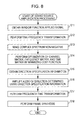
- This sound source amplification processing is initiated when the multichannel input signal is supplied to the time-frequency transform unit 61 and the direction information u is supplied to the direction specification unit 63 .
- the time-frequency transform unit 61 obtains the window function applied signal wx(c, n, l) by performing time frame division on the multichannel input signal x(c, t) supplied from the microphone 22 , and multiplying the multichannel frame signal obtained as a result by the window function.
- the window function applied signal wx(c, n, l) is calculated using the calculation in Expression (1).
- step S 12 the time-frequency transform unit 61 calculates the input complex spectra X(c, k, l), by performing a time-frequency transformation on the window function applied signal wx(c, n, l), and supplies the input complex spectrogram X formed from the input complex spectra X(c, k, l) to the sound source amplification unit 64 .
- the calculations of Expression (3) and Expression (4) are performed, and the input complex spectra X(c, k, l) are calculated.
- step S 13 the time-frequency transform unit 61 makes the input complex spectra X(c, k, l) non-negative, and supplies the non-negative spectrogram G formed from the obtained non-negative spectra G(c, k, l) to the sound source factorization unit 62 .
- the calculation of Expression (5) is performed, and the non-negative spectra G(c, k, l) are calculated.
- step S 14 the sound source factorization unit 62 performs optimization of the channel matrix Q, the frequency matrix W, and the time matrix H by minimizing the cost function C based on the non-negative spectrogram G supplied from the time-frequency transform unit 61 .
- the sound source factorization unit 62 obtains the channel matrix Q, the frequency matrix W, and the time matrix H using tensor factorization.
- the channel matrix Q in addition to the obtained channel matrix Q being supplied to the direction specification unit 63 , the channel matrix Q, the frequency matrix W, and the time matrix H are supplied to the sound source amplification unit 64 .
- step S 15 based on the supplied direction information u and the channel matrix Q supplied from the sound source factorization unit 62 , the direction specification unit 63 obtains the direction specification information q, and supplies the direction specification information q to the sound source amplification unit 64 .
- the calculation of Expression (26) is performed, and the direction specification information q is obtained.
- step S 16 based on the input complex spectrum X from the time-frequency transform unit 61 , the channel matrix Q, the frequency matrix W, and the time matrix H from the sound source factorization unit 62 , the sound source amplification unit 64 amplifies the audio from the direction determined according to the direction specification information q from the direction specification unit 63 .
- the sound source amplification unit 64 amplifies the audio from the designated direction in addition to attenuating the audio from directions which are different to the designated direction, and supplies the output time-frequency spectrum Y(c, k, l) obtained as a result to the frequency-time transform unit 65 .
- step S 17 the frequency-time transform unit 65 performs the frequency-time transformation on the output time-frequency spectrum Y(c, k, l) supplied from the sound source amplification unit 64 .
- the calculations of Expression (29) and Expression (30) are performed, and the multichannel output frame signal y′(c, n, l) is calculated.
- step S 18 the frequency-time transform unit 65 performs frame synthesis by multiplying the multichannel output frame signal y′(c, n, l) by the window function and performing the Overlap-Add, outputs the multichannel output signal y(c, t) to the earphone 23 , and the sound source amplification processing finishes.
- the calculation of Expression (32) is performed, and the multichannel output signal y(c,t) is calculated.
- the direction designated audio amplifier 51 factorizes the non-negative spectrogram into the channel matrix Q, the frequency matrix W, and the time matrix H using tensor factorization. Furthermore, the direction designated audio amplifier 51 amplifies a component specified from the channel matrix Q and the direction information u as the audio from a sound source in the desired direction.
- the series of processes described above may be executed using hardware, and may also be executed using software.
- a program which configures the software is installed on the computer.
- the term computer includes, for example, a computer embedded in dedicated hardware, an ordinary personal computer in which it is possible to execute various functions by installing various programs thereon, or the like.
- FIG. 9 is a block diagram showing an example of the configuration of the hardware of a computer which executes the series of processes described above using a program.
- the CPU Central Processing Unit
- the ROM Read Only Memory
- the RAM Random Access Memory
- An input output interface 205 is further connected to the bus 204 .
- An input unit 206 , an output unit 207 , a storage unit 208 , a communication unit 209 , and a drive 210 are connected to the input output interface 205 .
- the input unit 206 is formed from a keyboard, a mouse, a microphone, an imaging device, or the like.
- the output unit 207 is formed from a display, a speaker, and the like.
- the storage unit 208 is formed from a hard disk, non-volatile memory, or the like.
- the communication unit 209 is formed from a network interface or the like.
- the drive 210 drives removable media 211 such as a magnetic disk, an optical disc, a magneto-optical disc, or solid state memory.
- the CPU 201 performs the above described series of processes by loading the program stored in the storage unit 208 into the RAM 203 via the input output interface 205 and the bus 204 and performing execution.
- the program executed by the computer may be provided stored on the removable media 211 as packaged media or the like.
- the program may be provided via a wired or wireless transmission medium such as a local area network, the Internet, or digital satellite broadcast.
- the program it is possible to install the program onto the storage unit 208 via the input output interface 205 by inserting the removable media 211 into the drive 210 .
- the program may be received by the communication unit 209 via a wired or wireless transmission medium and installed to the storage unit 208 . It is also possible to install the program to the ROM 202 or the storage unit 208 in advance.
- the program executed by the computer may be a program in which processing is performed in time series in the order described in the present specification, and may also be a program in which processing is performed in parallel, or, at a necessary timing such as when a call is performed.
- the present technology may adopt a cloud computing configuration in which one function is shared by a plurality of devices via a network, and processing is performed in collaboration.
- each step described in the above described flowchart may, in addition to being executed on one device, be shared by a plurality of devices and executed.
- the plurality of processes included in the one step may, in addition to being executed on one device, be shared by a plurality of devices and executed.
- An audio processing device including a factorization unit which factorizes frequency information obtained by performing time-frequency transformation on an audio signal from a plurality of channels into a channel matrix representing characteristics of a channel direction, a frequency matrix representing characteristics of a frequency direction, and a time matrix representing characteristics of a time direction; and an extraction unit which extracts the frequency information of audio from an arbitrary designated direction based on the channel matrix, the frequency matrix, and the time matrix.
- the audio processing device further including a direction specification unit which obtains direction specification information specifying a matrix component relating to audio from the designated direction based on direction information and the channel matrix representing the designated direction; in which the extraction unit extracts the frequency information of audio from the designated direction based on the channel matrix, the frequency matrix, as well as the time matrix and the direction specification information.
- the factorization unit assumes that the frequency information is a three-dimensional tensor where a channel, a frequency, and a time frame are respective dimensions, and factorizes the frequency information into the channel matrix, the frequency matrix, and the time matrix by performing tensor factorization.
- the audio processing device further including a frequency-time transform unit which generates an audio signal from a plurality of channels by performing frequency-time transformation on the frequency information of audio from the designated direction obtained by the extraction unit.
Landscapes
- Physics & Mathematics (AREA)
- Engineering & Computer Science (AREA)
- Acoustics & Sound (AREA)
- Signal Processing (AREA)
- Stereophonic System (AREA)
- Circuit For Audible Band Transducer (AREA)
Abstract
Description
wx(c,n,l)=W ana(n)×x′(c,n,l) (1)
G(c,k,l)=(X(c,k,l)×conj(X(c,k,l)))γ (5)
S(W)=0 (20)
T(H)=|B·(H T H) (21)
∇W S(W)=0 (22)
∇H T(H)=2BH T (23)
Claims (8)
Applications Claiming Priority (3)
| Application Number | Priority Date | Filing Date | Title |
|---|---|---|---|
| EP12306403.2 | 2012-11-13 | ||
| EP12306403.2A EP2731359B1 (en) | 2012-11-13 | 2012-11-13 | Audio processing device, method and program |
| EP12306403 | 2012-11-13 |
Publications (2)
| Publication Number | Publication Date |
|---|---|
| US20140133674A1 US20140133674A1 (en) | 2014-05-15 |
| US9426564B2 true US9426564B2 (en) | 2016-08-23 |
Family
ID=47594444
Family Applications (1)
| Application Number | Title | Priority Date | Filing Date |
|---|---|---|---|
| US14/072,050 Expired - Fee Related US9426564B2 (en) | 2012-11-13 | 2013-11-05 | Audio processing device, method and program |
Country Status (3)
| Country | Link |
|---|---|
| US (1) | US9426564B2 (en) |
| EP (1) | EP2731359B1 (en) |
| CN (1) | CN103811023B (en) |
Cited By (1)
| Publication number | Priority date | Publication date | Assignee | Title |
|---|---|---|---|---|
| US20160074752A1 (en) * | 2014-09-12 | 2016-03-17 | Voyetra Turtle Beach, Inc. | Gaming headset with enhanced off-screen awareness |
Families Citing this family (11)
| Publication number | Priority date | Publication date | Assignee | Title |
|---|---|---|---|---|
| US9460732B2 (en) | 2013-02-13 | 2016-10-04 | Analog Devices, Inc. | Signal source separation |
| JP2014215461A (en) * | 2013-04-25 | 2014-11-17 | ソニー株式会社 | Speech processing device, method, and program |
| US9420368B2 (en) * | 2013-09-24 | 2016-08-16 | Analog Devices, Inc. | Time-frequency directional processing of audio signals |
| US9351060B2 (en) | 2014-02-14 | 2016-05-24 | Sonic Blocks, Inc. | Modular quick-connect A/V system and methods thereof |
| US20160071526A1 (en) * | 2014-09-09 | 2016-03-10 | Analog Devices, Inc. | Acoustic source tracking and selection |
| KR20160102815A (en) * | 2015-02-23 | 2016-08-31 | 한국전자통신연구원 | Robust audio signal processing apparatus and method for noise |
| US9668066B1 (en) * | 2015-04-03 | 2017-05-30 | Cedar Audio Ltd. | Blind source separation systems |
| CN110164470A (en) * | 2019-06-12 | 2019-08-23 | 成都嗨翻屋科技有限公司 | Voice separation method, device, user terminal and storage medium |
| CN110400575B (en) | 2019-07-24 | 2024-03-29 | 腾讯科技(深圳)有限公司 | Inter-channel feature extraction method, audio separation method and device, computing device |
| CN111583916B (en) * | 2020-05-19 | 2023-07-25 | 科大讯飞股份有限公司 | Voice recognition method, device, equipment and storage medium |
| CN111862989B (en) * | 2020-06-01 | 2024-03-08 | 北京捷通华声科技股份有限公司 | Acoustic feature processing method and device |
Citations (6)
| Publication number | Priority date | Publication date | Assignee | Title |
|---|---|---|---|---|
| US20050222840A1 (en) * | 2004-03-12 | 2005-10-06 | Paris Smaragdis | Method and system for separating multiple sound sources from monophonic input with non-negative matrix factor deconvolution |
| US20070112818A1 (en) * | 2005-11-17 | 2007-05-17 | Nishanth Sastry | Method and system for nested categorization using factorization |
| US20080298597A1 (en) | 2007-05-30 | 2008-12-04 | Nokia Corporation | Spatial Sound Zooming |
| US20100138010A1 (en) * | 2008-11-28 | 2010-06-03 | Audionamix | Automatic gathering strategy for unsupervised source separation algorithms |
| US20110054848A1 (en) | 2009-08-28 | 2011-03-03 | Electronics And Telecommunications Research Institute | Method and system for separating musical sound source |
| US20110081024A1 (en) | 2009-10-05 | 2011-04-07 | Harman International Industries, Incorporated | System for spatial extraction of audio signals |
Family Cites Families (3)
| Publication number | Priority date | Publication date | Assignee | Title |
|---|---|---|---|---|
| JP4462617B2 (en) | 2004-11-29 | 2010-05-12 | 株式会社神戸製鋼所 | Sound source separation device, sound source separation program, and sound source separation method |
| JP5195652B2 (en) * | 2008-06-11 | 2013-05-08 | ソニー株式会社 | Signal processing apparatus, signal processing method, and program |
| JP2012163918A (en) * | 2011-02-09 | 2012-08-30 | Sony Corp | Voice signal processing apparatus, voice signal processing method, and program |
-
2012
- 2012-11-13 EP EP12306403.2A patent/EP2731359B1/en not_active Not-in-force
-
2013
- 2013-11-05 US US14/072,050 patent/US9426564B2/en not_active Expired - Fee Related
- 2013-11-05 CN CN201310540742.9A patent/CN103811023B/en not_active Expired - Fee Related
Patent Citations (6)
| Publication number | Priority date | Publication date | Assignee | Title |
|---|---|---|---|---|
| US20050222840A1 (en) * | 2004-03-12 | 2005-10-06 | Paris Smaragdis | Method and system for separating multiple sound sources from monophonic input with non-negative matrix factor deconvolution |
| US20070112818A1 (en) * | 2005-11-17 | 2007-05-17 | Nishanth Sastry | Method and system for nested categorization using factorization |
| US20080298597A1 (en) | 2007-05-30 | 2008-12-04 | Nokia Corporation | Spatial Sound Zooming |
| US20100138010A1 (en) * | 2008-11-28 | 2010-06-03 | Audionamix | Automatic gathering strategy for unsupervised source separation algorithms |
| US20110054848A1 (en) | 2009-08-28 | 2011-03-03 | Electronics And Telecommunications Research Institute | Method and system for separating musical sound source |
| US20110081024A1 (en) | 2009-10-05 | 2011-04-07 | Harman International Industries, Incorporated | System for spatial extraction of audio signals |
Non-Patent Citations (9)
| Title |
|---|
| A, et al., "Nonnegative Matrix and Tensor Factorizations-Applications to Exploratory Multi-way Data Analysis and Blind Source Separation", http://www.bsp.brain.riken.jp/~cia/recent.html (retrieved Mar. 14, 2013), Sep. 1, 2009, 2 pages. |
| A, et al., "Nonnegative Matrix and Tensor Factorizations-Applications to Exploratory Multi-way Data Analysis and Blind Source Separation", http://www.bsp.brain.riken.jp/˜cia/recent.html (retrieved Mar. 14, 2013), Sep. 1, 2009, 2 pages. |
| Alexey Ozerov, et al., "Multichannel Nonnegative Tensor Factorization With Structured Constraints for User-Guided Audio Source Separation", 2011 IEEE International Conference on Acoustics, Speech and Signal Processing (ICASSP), May 22, 2011, 4 pages. |
| European Search Report issued Mar. 22, 2013, in European Application No. 12306403.2 filed Nov. 13, 2012. |
| Fevotte et al, Notes on nonnegative tensor factorization of the spectrogram for audio separation statistical insight and towards self clusteing of the spatial cues, 2011. * |
| Fitzgerald et al, Non negative tensor factorization for sound source separation, ISSC 2005. * |
| J. Nikunen, et al., "Multichannel Audio Upmixing Based on Non-Negative Tensor Factorization Representation", 2011 IEEE Workshop on Applications of Signal Processing to Audio and Acoustics (WASPAA), Oct. 16-19, 2011, 4 pages. |
| Lee et al, Beamspace Domain multichannel nonnegative matrix factorization for audio sources separation, IEEE Jan. 2012. * |
| Sawada et al, Multichannel extensions of nonnegative matrix factorization with complex valued data, IEEE. * |
Cited By (11)
| Publication number | Priority date | Publication date | Assignee | Title |
|---|---|---|---|---|
| US20160074752A1 (en) * | 2014-09-12 | 2016-03-17 | Voyetra Turtle Beach, Inc. | Gaming headset with enhanced off-screen awareness |
| US9782672B2 (en) * | 2014-09-12 | 2017-10-10 | Voyetra Turtle Beach, Inc. | Gaming headset with enhanced off-screen awareness |
| US10232256B2 (en) | 2014-09-12 | 2019-03-19 | Voyetra Turtle Beach, Inc. | Gaming headset with enhanced off-screen awareness |
| US10709974B2 (en) | 2014-09-12 | 2020-07-14 | Voyetra Turtle Beach, Inc. | Gaming headset with enhanced off-screen awareness |
| US11484786B2 (en) | 2014-09-12 | 2022-11-01 | Voyetra Turtle Beach, Inc. | Gaming headset with enhanced off-screen awareness |
| US11938397B2 (en) | 2014-09-12 | 2024-03-26 | Voyetra Turtle Beach, Inc. | Hearing device with enhanced awareness |
| US11944899B2 (en) | 2014-09-12 | 2024-04-02 | Voyetra Turtle Beach, Inc. | Wireless device with enhanced awareness |
| US11944898B2 (en) | 2014-09-12 | 2024-04-02 | Voyetra Turtle Beach, Inc. | Computing device with enhanced awareness |
| US12330052B2 (en) | 2014-09-12 | 2025-06-17 | Voyetra Turtle Beach, Inc. | Wireless device with enhanced awareness |
| US12330053B2 (en) | 2014-09-12 | 2025-06-17 | Voyetra Turtle Beach, Inc. | Computing device with enhanced awareness |
| US12343617B2 (en) | 2014-09-12 | 2025-07-01 | Voyetra Turtle Beach, Inc. | Hearing device with enhanced awareness |
Also Published As
| Publication number | Publication date |
|---|---|
| EP2731359B1 (en) | 2015-10-14 |
| CN103811023A (en) | 2014-05-21 |
| CN103811023B (en) | 2018-11-16 |
| US20140133674A1 (en) | 2014-05-15 |
| EP2731359A1 (en) | 2014-05-14 |
Similar Documents
| Publication | Publication Date | Title |
|---|---|---|
| US9426564B2 (en) | Audio processing device, method and program | |
| EP3259755B1 (en) | Separating audio sources | |
| CN104123948B (en) | Sound processing apparatus, sound processing method and storage medium | |
| EP3257044B1 (en) | Audio source separation | |
| US11943604B2 (en) | Spatial audio processing | |
| KR20200115731A (en) | Method and apparatus for recognition of sound events based on convolutional neural network | |
| US8364483B2 (en) | Method for separating source signals and apparatus thereof | |
| EP3133833B1 (en) | Sound field reproduction apparatus, method and program | |
| EP2355097B1 (en) | Signal separation system and method | |
| CN114203163A (en) | Audio signal processing method and device | |
| HK1244104A1 (en) | Audio source separation | |
| US9966081B2 (en) | Method and apparatus for synthesizing separated sound source | |
| US9704505B2 (en) | Audio signal processing apparatus and method | |
| US10410641B2 (en) | Audio source separation | |
| KR102590887B1 (en) | Sound source separation method using spatial position of the sound source and non-negative matrix factorization and apparatus performing the method | |
| Grais et al. | Discriminative enhancement for single channel audio source separation using deep neural networks | |
| Sheeja et al. | Speech dereverberation and source separation using DNN-WPE and LWPR-PCA | |
| Koteswararao et al. | Multichannel KHMF for speech separation with enthalpy based DOA and score based CNN (SCNN) | |
| WO2023192046A1 (en) | Context aware audio capture and rendering | |
| Fontaine et al. | Multichannel audio modeling with elliptically stable tensor decomposition | |
| Corey et al. | Relative transfer function estimation from speech keywords | |
| Narvor et al. | Audiovisual speech separation based on independent vector analysis using a visual voice activity detector | |
| CN120612902A (en) | Method, apparatus, device, medium, and program product for mixing audio | |
| Cabras | Advanced component analysis techniques for signal decomposition and their applications to audio restoration and volcanic seismology. | |
| Koldovský et al. | Improving Relative Transfer Function Estimates Using Second-Order Cone Programming |
Legal Events
| Date | Code | Title | Description |
|---|---|---|---|
| AS | Assignment |
Owner name: INSTITUT DE RECHERCHE ET COORDINATION ACOUSTIQUE/M Free format text: ASSIGNMENT OF ASSIGNORS INTEREST;ASSIGNORS:MITSUFUJI, YUHKI;ROEBEL, AXEL;SIGNING DATES FROM 20130902 TO 20131020;REEL/FRAME:031581/0771 Owner name: SONY CORPORATION, JAPAN Free format text: ASSIGNMENT OF ASSIGNORS INTEREST;ASSIGNORS:MITSUFUJI, YUHKI;ROEBEL, AXEL;SIGNING DATES FROM 20130902 TO 20131020;REEL/FRAME:031581/0771 |
|
| FEPP | Fee payment procedure |
Free format text: PAYOR NUMBER ASSIGNED (ORIGINAL EVENT CODE: ASPN); ENTITY STATUS OF PATENT OWNER: LARGE ENTITY |
|
| ZAAA | Notice of allowance and fees due |
Free format text: ORIGINAL CODE: NOA |
|
| ZAAB | Notice of allowance mailed |
Free format text: ORIGINAL CODE: MN/=. |
|
| STCF | Information on status: patent grant |
Free format text: PATENTED CASE |
|
| MAFP | Maintenance fee payment |
Free format text: PAYMENT OF MAINTENANCE FEE, 4TH YEAR, LARGE ENTITY (ORIGINAL EVENT CODE: M1551); ENTITY STATUS OF PATENT OWNER: LARGE ENTITY Year of fee payment: 4 |
|
| FEPP | Fee payment procedure |
Free format text: MAINTENANCE FEE REMINDER MAILED (ORIGINAL EVENT CODE: REM.); ENTITY STATUS OF PATENT OWNER: LARGE ENTITY |
|
| LAPS | Lapse for failure to pay maintenance fees |
Free format text: PATENT EXPIRED FOR FAILURE TO PAY MAINTENANCE FEES (ORIGINAL EVENT CODE: EXP.); ENTITY STATUS OF PATENT OWNER: LARGE ENTITY |
|
| STCH | Information on status: patent discontinuation |
Free format text: PATENT EXPIRED DUE TO NONPAYMENT OF MAINTENANCE FEES UNDER 37 CFR 1.362 |
|
| FP | Lapsed due to failure to pay maintenance fee |
Effective date: 20240823 |