US941663A - Hydraulic separator. - Google Patents
Hydraulic separator. Download PDFInfo
- Publication number
- US941663A US941663A US25000705A US1905250007A US941663A US 941663 A US941663 A US 941663A US 25000705 A US25000705 A US 25000705A US 1905250007 A US1905250007 A US 1905250007A US 941663 A US941663 A US 941663A
- Authority
- US
- United States
- Prior art keywords
- sluice
- box
- agitators
- gate
- hydraulic separator
- Prior art date
- Legal status (The legal status is an assumption and is not a legal conclusion. Google has not performed a legal analysis and makes no representation as to the accuracy of the status listed.)
- Expired - Lifetime
Links
- 239000000463 material Substances 0.000 description 11
- 238000004140 cleaning Methods 0.000 description 4
- XLYOFNOQVPJJNP-UHFFFAOYSA-N water Substances O XLYOFNOQVPJJNP-UHFFFAOYSA-N 0.000 description 4
- 239000012141 concentrate Substances 0.000 description 2
- 238000010276 construction Methods 0.000 description 2
- 230000004048 modification Effects 0.000 description 2
- 238000012986 modification Methods 0.000 description 2
- 239000007787 solid Substances 0.000 description 2
- 101100434906 Mus musculus Angptl8 gene Proteins 0.000 description 1
- 230000003292 diminished effect Effects 0.000 description 1
- 230000005484 gravity Effects 0.000 description 1
- 230000002452 interceptive effect Effects 0.000 description 1
- 239000004576 sand Substances 0.000 description 1
Images
Classifications
-
- B—PERFORMING OPERATIONS; TRANSPORTING
- B03—SEPARATION OF SOLID MATERIALS USING LIQUIDS OR USING PNEUMATIC TABLES OR JIGS; MAGNETIC OR ELECTROSTATIC SEPARATION OF SOLID MATERIALS FROM SOLID MATERIALS OR FLUIDS; SEPARATION BY HIGH-VOLTAGE ELECTRIC FIELDS
- B03B—SEPARATING SOLID MATERIALS USING LIQUIDS OR USING PNEUMATIC TABLES OR JIGS
- B03B5/00—Washing granular, powdered or lumpy materials; Wet separating
- B03B5/48—Washing granular, powdered or lumpy materials; Wet separating by mechanical classifiers
Definitions
- Objects of the present invention are to prevent worthless material of high specific gravity, such. as magnetic sand and the like, from lodging in a comparatively solid mass and occupying the spaces between the rifiies where it would prevent the contained values from finding a place for lodgment; to provide an apparatus which may be subjected to the operation known as cleaning up without suspending the performance ofits ordinary functions; to provide portable apparatus adapted to improve the operation and capable of application in various localities; and to facilitate the performance of the cleaning up operation.
- high specific gravity such. as magnetic sand and the like
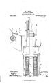
- Figure 1 is a top or plan view of apparatus embodying features of the invention.
- Fig. 2 is a view partly in section and partly in elevation of the same.
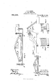
- Fig. 3 is a View principally in section illustrating a modification of the invention.
- Fig. 4 is a sectional view illustrating a portion of the apparatus shown in Figs. 1 and 2
- Figs. 5 and 6 are perspective views illustrating details of one type of construction of movable ritlle and agitator.
- FIG. 1 may be designated as the head of sluice box or boxes provided with a suitable hopper 6, a rotary screen 3, and a water supply 4.
- the material to be treated is moved from the bank or deposit by means of the elevator 2, and delivered into the hopper 6, from which it passes into the revolving screen 3, the coarse material escaping from the end opening of the revolvlng screen and the fine material, including the values and considerable water, escaping through the perforations in the re- 1Solving screen into the head of the sluice
- This description is of one type of apparatus which, of course, may be replaced by a variety of types of apparatus designed to operate so as to deliver the comparatively fine material which contains the value to be recovered to the systems of agitators and movable ritlles, to be presently described.
- each flume or slice-box there is a system of movable rifiles and agitators.
- This element is shown to consist of endless belts or sprocket chains 10 and their appropriate wheels 11, 12 and 13.
- These belts or sprocket chains are provided with agitators and movable riflies of suitable construction and adapted to be moved in the direction of the head of the sluice boxes. Examples of riflies and agitators are shown in Figs. 5 and 6, in which a is the agitator part and b, the riflie part, but the parts are capable of various embodiments.
- the wheels 11, 12 and 13 may be mounted upon axles permanently connected with the flume or sluice box as shown in Fig. 3, or they may be arranged upon a frame 16, as shown in Fig. 2, consisting of two arms and which frame can be detachably connected with the sluice-boxes so that it can be moved from one to another.
- the frame may be pivoted to the sluice-box as at 17, so that it can be turned up out of the sluicebox in order to facilitate the operation of cleaning-up
- Each sluice-box is provided at its discharge end with a gate 18 which permits of adjustment of the depth of material and water in the sluice-box.
- 21, 22, 23 and 24 indicate belts or sprocket chains and their connections, which receive poWer as from the belt or sprocket chain 25 and transmit it .to the various movable parts which have been described.
- Normally gate 19 is open and gate 18 properly adjusted, and water and material are flowing.
- the rifiies and agitators are moving in the direction of the source of supply and they serve to move the contained values toward the head of the box, keeping the material meanwhile agitated, so that suspended matter passes out of the box over the gate 18 and retaining in the box at or near its head the heavy concentrates containing the values; while at the same time the movement of the riflies and agitators prevents undesirable lodgment of heavy material.
- the gate 19 is closed and the moving riffies and agitators draw the concentrates toward the gate 20 through which they pass and are collected.
Landscapes
- Separation Of Solids By Using Liquids Or Pneumatic Power (AREA)
Description
W. F. SMI TH. HYDRAULIC SEPARATOR. APPLICATION FILED MAR.14, 190a.
Patented Nov. 30, 1909.
2 SHEETS-SHEET 1.
WW M
Muww
Aumzw. I. GMMII no. mommmmmms wnsvunumn. n a
W. F. SMITH. HYDRAULIC SEPARATOR. APPLICATION FILED MAR. 14, 1905.
2 SHEETS-SHEET 2.
Cf Q m.
1 mas M e I qQWW wi 39X0MW U- 7 2 I ANDREW a. GRAHAM cm. PRDTO-U'DIQGRAPNERS. wnsumm'ngl. n. c.
siren srArEs reins.
HYDRAULIC SEPARATOR.
Specification of Letters Patent.
Patented Nov. 36, 1969.
Application filed March 14, 1905. Serial No. 250,007.
To all whom it may concern:
Be it known that I, -WALTER F. SMITH, a citizen of the United States, residing at Philadelphia, in the county of Philadelphia and State of Pennsylvania, have invented certain new and useful Improvements in Hydraulic Separators, of which the following is a specification.
Objects of the present invention are to prevent worthless material of high specific gravity, such. as magnetic sand and the like, from lodging in a comparatively solid mass and occupying the spaces between the rifiies where it would prevent the contained values from finding a place for lodgment; to provide an apparatus which may be subjected to the operation known as cleaning up without suspending the performance ofits ordinary functions; to provide portable apparatus adapted to improve the operation and capable of application in various localities; and to facilitate the performance of the cleaning up operation.
To these and other ends hereinafter set forth the invention comprises the improvements to be presently described and finally claimed.
The nature, characteristic features and scope of the invention will be more fully understood from the following description taken in connection with the accompanying drawings forming part hereof and in which Figure 1, is a top or plan view of apparatus embodying features of the invention. Fig. 2, is a view partly in section and partly in elevation of the same. Fig. 3, is a View principally in section illustrating a modification of the invention. Fig. 4, is a sectional view illustrating a portion of the apparatus shown in Figs. 1 and 2, and Figs. 5 and 6, are perspective views illustrating details of one type of construction of movable ritlle and agitator.
In the drawings 1, may be designated as the head of sluice box or boxes provided with a suitable hopper 6, a rotary screen 3, and a water supply 4. The material to be treated is moved from the bank or deposit by means of the elevator 2, and delivered into the hopper 6, from which it passes into the revolving screen 3, the coarse material escaping from the end opening of the revolvlng screen and the fine material, including the values and considerable water, escaping through the perforations in the re- 1Solving screen into the head of the sluice This description is of one type of apparatus which, of course, may be replaced by a variety of types of apparatus designed to operate so as to deliver the comparatively fine material which contains the value to be recovered to the systems of agitators and movable ritlles, to be presently described.
7, is a reservoir which receives the fine material and it is arranged so as to communicate with and be common to the sluice boxes or fiumes, of which two, 8 and 9, are shown, although the number may be increased or diminished.
In each flume or slice-box there is a system of movable rifiles and agitators. This element is shown to consist of endless belts or sprocket chains 10 and their appropriate wheels 11, 12 and 13. These belts or sprocket chains are provided with agitators and movable riflies of suitable construction and adapted to be moved in the direction of the head of the sluice boxes. Examples of riflies and agitators are shown in Figs. 5 and 6, in which a is the agitator part and b, the riflie part, but the parts are capable of various embodiments. As shown they are suspended from the belts 10 and provided with lugs or stops in such a way that they are rigid when in operative position and turn down onto the belts when in inoperative position. The wheels 11, 12 and 13 may be mounted upon axles permanently connected with the flume or sluice box as shown in Fig. 3, or they may be arranged upon a frame 16, as shown in Fig. 2, consisting of two arms and which frame can be detachably connected with the sluice-boxes so that it can be moved from one to another. If desired, the frame may be pivoted to the sluice-box as at 17, so that it can be turned up out of the sluicebox in order to facilitate the operation of cleaning-up Each sluice-box is provided at its discharge end with a gate 18 which permits of adjustment of the depth of material and water in the sluice-box. There is a gate 19 at the head end of each sluice-box and the gate 19 that appertains to any sluice-box may be closed while it is being cleaned up, without interfering with the normal operaof the material which is to be saved durin tion of the other sluice-boxes, Whose gates 19 are open.
20, are gates Which facilitate the removal g the cleaning up operation.
21, 22, 23 and 24 indicate belts or sprocket chains and their connections, which receive poWer as from the belt or sprocket chain 25 and transmit it .to the various movable parts which have been described.
Normally gate 19 is open and gate 18 properly adjusted, and water and material are flowing. The rifiies and agitators are moving in the direction of the source of supply and they serve to move the contained values toward the head of the box, keeping the material meanwhile agitated, so that suspended matter passes out of the box over the gate 18 and retaining in the box at or near its head the heavy concentrates containing the values; while at the same time the movement of the riflies and agitators prevents undesirable lodgment of heavy material. In cleaning up the sluice-box the gate 19 is closed and the moving riffies and agitators draw the concentrates toward the gate 20 through which they pass and are collected.
It will be obvious to those skilled in the art to which the invention relates that modifications may be made in details without dcparting from the spirit thereof, hence the invention is not limited further than the prior state of the art may require, but
Having thus described the nature and objects of my invention what I claim as new and desire to secure by Letters Patent is In a hydraulic separator, the combination of a flume or sluice box and a series of movable rifl'les and agitators of which each extends entirely across the width of the box and comprises a solid lower part which operates as a rifiie and a grate-like upper part which acts as an agitator, substantially as described.
In testimony whereof I have hereunto signed my name.
IVALTER F. SMITH.
lVitnesses W. J. JAcKsoN, K. M. GILLIGAN.
Priority Applications (1)
| Application Number | Priority Date | Filing Date | Title |
|---|---|---|---|
| US25000705A US941663A (en) | 1905-03-14 | 1905-03-14 | Hydraulic separator. |
Applications Claiming Priority (1)
| Application Number | Priority Date | Filing Date | Title |
|---|---|---|---|
| US25000705A US941663A (en) | 1905-03-14 | 1905-03-14 | Hydraulic separator. |
Publications (1)
| Publication Number | Publication Date |
|---|---|
| US941663A true US941663A (en) | 1909-11-30 |
Family
ID=3010085
Family Applications (1)
| Application Number | Title | Priority Date | Filing Date |
|---|---|---|---|
| US25000705A Expired - Lifetime US941663A (en) | 1905-03-14 | 1905-03-14 | Hydraulic separator. |
Country Status (1)
| Country | Link |
|---|---|
| US (1) | US941663A (en) |
-
1905
- 1905-03-14 US US25000705A patent/US941663A/en not_active Expired - Lifetime
Similar Documents
| Publication | Publication Date | Title |
|---|---|---|
| US941663A (en) | Hydraulic separator. | |
| US1135754A (en) | Fine-ore separator. | |
| US565151A (en) | Territory | |
| US206115A (en) | Improvement in ore-separators | |
| US828963A (en) | Concentrator. | |
| US269563A (en) | Ore concentrator and amalgamator | |
| US1039206A (en) | Classifying or grading apparatus. | |
| US1030499A (en) | Gold-saving machine. | |
| US775948A (en) | Ore-washer. | |
| US967745A (en) | Gold-saving riffle. | |
| US1207452A (en) | Tabular ore washer or concentrator. | |
| US758565A (en) | Ore-concentrator. | |
| US344720A (en) | Machine for concentrating ores | |
| US394654A (en) | Concentrator | |
| US2164364A (en) | Placer gold concentrator and amalgamator | |
| US812474A (en) | Gold-saving apparatus. | |
| US2170069A (en) | Apparatus for mineral separation | |
| US300479A (en) | Teeeitoet | |
| US1049257A (en) | Separator. | |
| US1368901A (en) | Ore-separator | |
| US1190306A (en) | Ore-concentrator. | |
| US671116A (en) | Concentrator. | |
| US618006A (en) | Apparatus for concentrating and amalgamating preciqu | |
| US252569A (en) | Ore washer | |
| US703084A (en) | Ore-separator. |