US9413357B2 - Hierarchical statistically multiplexed counters and a method thereof - Google Patents
Hierarchical statistically multiplexed counters and a method thereof Download PDFInfo
- Publication number
- US9413357B2 US9413357B2 US14/302,351 US201414302351A US9413357B2 US 9413357 B2 US9413357 B2 US 9413357B2 US 201414302351 A US201414302351 A US 201414302351A US 9413357 B2 US9413357 B2 US 9413357B2
- Authority
- US
- United States
- Prior art keywords
- counter
- counters
- level
- levels
- overflow
- Prior art date
- Legal status (The legal status is an assumption and is not a legal conclusion. Google has not performed a legal analysis and makes no representation as to the accuracy of the status listed.)
- Active, expires
Links
- 238000000034 method Methods 0.000 title description 29
- 238000013507 mapping Methods 0.000 claims description 28
- 230000015654 memory Effects 0.000 description 16
- 239000011449 brick Substances 0.000 description 15
- 238000010586 diagram Methods 0.000 description 8
- 230000008569 process Effects 0.000 description 6
- 230000006870 function Effects 0.000 description 4
- 230000008878 coupling Effects 0.000 description 1
- 238000010168 coupling process Methods 0.000 description 1
- 238000005859 coupling reaction Methods 0.000 description 1
- 238000012517 data analytics Methods 0.000 description 1
- 230000000694 effects Effects 0.000 description 1
- 230000007246 mechanism Effects 0.000 description 1
- 230000003068 static effect Effects 0.000 description 1
Images


Classifications
-
- H—ELECTRICITY
- H03—ELECTRONIC CIRCUITRY
- H03K—PULSE TECHNIQUE
- H03K21/00—Details of pulse counters or frequency dividers
- H03K21/02—Input circuits
- H03K21/026—Input circuits comprising logic circuits
-
- H—ELECTRICITY
- H03—ELECTRONIC CIRCUITRY
- H03K—PULSE TECHNIQUE
- H03K23/00—Pulse counters comprising counting chains; Frequency dividers comprising counting chains
- H03K23/64—Pulse counters comprising counting chains; Frequency dividers comprising counting chains with a base or radix other than a power of two
-
- H—ELECTRICITY
- H04—ELECTRIC COMMUNICATION TECHNIQUE
- H04L—TRANSMISSION OF DIGITAL INFORMATION, e.g. TELEGRAPHIC COMMUNICATION
- H04L47/00—Traffic control in data switching networks
- H04L47/50—Queue scheduling
- H04L47/62—Queue scheduling characterised by scheduling criteria
-
- H—ELECTRICITY
- H04—ELECTRIC COMMUNICATION TECHNIQUE
- H04L—TRANSMISSION OF DIGITAL INFORMATION, e.g. TELEGRAPHIC COMMUNICATION
- H04L49/00—Packet switching elements
- H04L49/90—Buffering arrangements
- H04L49/9084—Reactions to storage capacity overflow
-
- H—ELECTRICITY
- H03—ELECTRONIC CIRCUITRY
- H03K—PULSE TECHNIQUE
- H03K21/00—Details of pulse counters or frequency dividers
-
- H—ELECTRICITY
- H03—ELECTRONIC CIRCUITRY
- H03K—PULSE TECHNIQUE
- H03K23/00—Pulse counters comprising counting chains; Frequency dividers comprising counting chains
-
- H—ELECTRICITY
- H03—ELECTRONIC CIRCUITRY
- H03K—PULSE TECHNIQUE
- H03K23/00—Pulse counters comprising counting chains; Frequency dividers comprising counting chains
- H03K23/004—Counters counting in a non-natural counting order, e.g. random counters
-
- H—ELECTRICITY
- H03—ELECTRONIC CIRCUITRY
- H03K—PULSE TECHNIQUE
- H03K23/00—Pulse counters comprising counting chains; Frequency dividers comprising counting chains
- H03K23/004—Counters counting in a non-natural counting order, e.g. random counters
- H03K23/005—Counters counting in a non-natural counting order, e.g. random counters using minimum change code, e.g. Gray Code
Definitions
- the present invention relates to counters in a high speed network switch. More particularly, the present invention relates to hierarchical statistically multiplexed counters and a method thereof.
- Statistics counters are used to perform data analytics in a high speed network device. To be useful, an architecture needs to store a large number of counters. Although off-chip DRAM (dynamic random access memory) can be used, it cannot accommodate high speed counter updates. On-chip SRAM (static random access memory) allows for greater speed but is very expensive. Since the memory is one of the most expensive resources in an SOC (system on chip), it is critical to efficiently and flexibly utilize the memory. When dealing with storing multiple counters, there exists a tradeoff between fewer larger counters or more smaller counters. Ideally, each counter is long enough to avoid integer overflow, the wrapping around of the counter. However, in standard practice, this leads to overprovisioning, assigning the worst case number of bits for all counters.
- DRAM dynamic random access memory
- SRAM static random access memory
- Embodiments of the present invention relate to an architecture that uses hierarchical statistically multiplexed counters to extend counter life by orders of magnitude.
- Each level includes statistically multiplexed counters.
- the statistically multiplexed counters includes P base counters and S subcounters, wherein the S subcounters are dynamically concatenated with the P base counters.
- S subcounters are dynamically concatenated with the P base counters.
- a counter architecture is provided.
- the counter architecture is implemented in a network device, such as a network switch.
- the counter architecture includes a plurality of levels of statistically multiplexed counters.
- Each of the levels of statistically multiplexed counters includes N counters.
- the N counters are wrap-around.
- the N counters are arranged in N/P rows.
- Each of the N/P rows includes P base counters and S subcounters, wherein any of the P base counters can be dynamically concatenated with one or more of the S subcounters to flexibly extend the counting capacity.
- each of the P base counters initially uses one of the S subcounters.
- P is typically chosen as a power of two for optimal implementation
- the plurality of levels includes at least two levels. In some embodiments, the plurality of levels includes at least three levels.
- each of the N/P rows also includes an overhead, wherein the overhead is an S-bit mapping of the S subcounters to the P base counters. The mapping is updated upon counter expansion and upon counter shrinkage.
- counters in the same row in a first level of the plurality of levels are shuffled into different rows in a second level of the plurality of levels.
- a randomization of the shuffle is a bit reverse of a counter identifier of a counter, a hash function or a bit arrangement in another order.
- the counter architecture implements a mirrored shift logic, wherein the mirror shift logic includes a lower shift logic and an upper shift logic that is the mirror of the lower shift logic.
- a subcounter that has a rank ⁇ P/2 is associated with the lower shift logic, wherein the lower shift logic shifts the subcounter up.
- a subcounter that has a rank P/2 is associated with the upper shift logic, wherein the upper shift logic shifts the subcounter down.
- the rank of a subcounter is related to the assigned positions of previous subcounters to base counters.
- the counter architecture also includes an overflow FIFO used and shared by the N counters in the highest level in the plurality of levels, wherein the overflow FIFO stores associated counter identifiers of all counters that are overflowing along with overflow widths.
- the counter architecture also includes at least one interrupt sent to a CPU to read data in the overflow FIFO and to read and clear data in a counter from each of the plurality of levels.
- a counter architecture is provided.
- the counter architecture is implemented in a network device.
- the counter architecture includes a hierarchy of levels of statistically multiplexed counters, wherein each of the hierarchy of levels includes a plurality of rows of bits, wherein each row includes a first set of consecutive bits, a second set of consecutive bits and a third set of consecutive bits.
- the first set of consecutive bits is evenly shared by S subcounters
- the second set of consecutive bits is evenly shared by P base counters
- the third set of consecutive bits represents a mapping of the S subcounters to the P base counters.
- a counter is expanded by concatenating one or more of the S subcounters to one of the P base counters.
- a counter is shrunk by removing one or more of the S subcounters from one of the P base counters.
- counters in a next level above are used to extend counter life. In some embodiments, counters in the one level of the hierarchy are shuffled into different rows in the next level above of the hierarchy.
- the counter architecture also includes an overflow FIFO used and shared by all counters in the highest level in the hierarchy of levels, wherein the overflow FIFO stores associated counter identifiers of any of the counters that are overflowing in the highest level in the hierarchy of levels.
- a method of updating a counter in a counter architecture includes a hierarchy of levels of statistically multiplexed counters.
- the method includes determining whether a corresponding row of the counter in a current level of the hierarchy of levels overflows.
- the current level is the lowest level in the hierarchy of levels.
- the method includes, based on the determination that the corresponding row in the current level does not overflow, processing each level below the current level by using a first routine and processing the current level by using a second routine.
- the first routine includes incrementing the counter in the corresponding level and shrinking the counter in the corresponding level.
- the second routine includes incrementing the counter in the corresponding level, wherein a size of the counter in the corresponding level is expanded if necessary.
- the method includes, based on the determination that the corresponding row in the current level does overflow, determining whether a corresponding row of the counter in a next level above overflows.
- the method includes, based on the determination that the corresponding row of the counter in the next level above does not overflow, processing each level below the next level above by using the first routine and processing the next level above by using the second routine.
- the first routine includes incrementing the counter in the corresponding level and shrinking the counter in the corresponding level; and, the second routine includes incrementing the counter in the corresponding level, wherein a size of the counter in the corresponding level is expanded if necessary.
- the method includes, based on the determination that the corresponding row of the counter in the next level above does overflow, when the next level above is not the highest level in the hierarchy of levels, returning to the step of determining whether a corresponding row of the counter in a next level above overflow; otherwise, when the next level above is the highest level in the hierarchy of levels, processing the next level above and each level below the next level above by using the first routine and updating an overflow queue.
- the first routine includes incrementing the counter in the corresponding level and shrinking the counter in the corresponding level.
- the overflow queue updated by pushing a counter identifier of the counter and an overflow width into the overflow queue.
- the method also includes processing data in the overflow queue, identifying a wrap-around counter by the data in the overflow queue, reading a value stored of the identified counter in each level, and clearing the identified counter in each level.
- a method of updating a counter in a counter architecture includes a hierarchy of levels of statistically multiplexed counters.
- the method includes, upon occurrence of a first event, continuously processing each level below the highest level of the hierarchy by using a first routine and processing the highest level of the hierarchy by using a second routine.
- the method also includes, upon occurrence of a second event, continuously processing each level including and below the highest level of the hierarchy by the first routine and updating an overflow queue.
- the first event is there is a row overflow in each level below the highest level of the hierarchy but no row overflow in the highest level of the hierarchy.
- the second event is there is a row overflow in each level including and below the highest level of the hierarchy.
- the first routine includes incrementing the counter in the corresponding level and shrinking the counter in the corresponding level.
- the second routine includes incrementing the counter in the corresponding level.
- the incrementing the counter includes expanding a size of the counter in the corresponding level.
- updating the overflow queue includes pushing a counter identifier of the counter and an overflow width into the overflow queue.
- a network device in yet another aspect, includes a common memory pool, wherein memories from the common memory pool are separated into a plurality of banks.
- the network device also includes a counter architecture for extending counter life.
- the counter architecture includes a hierarchy of levels of statistically multiplexed counters. Each of the levels of statistically multiplexed counters includes N counters. In some embodiments, the N counters are stored in an on-chip SRAM memory, using the plurality of banks of memory.
- the N counters are arranged in N/P rows. Each of the N/P rows includes P base counters and S subcounters, wherein any of the P base counters can be dynamically concatenated with one or more of the S subcounters to flexibly extend the counting capacity.
- counters in the same row in one level of the hierarchy of levels are shuffled into different rows in a next level above of the hierarchy of levels.
- a randomization of the shuffle is a bit reverse of a counter identifier of a counter, a hash function or a bit arrangement in another order.
- the counter architecture further includes a mirrored shift logic to extend the P counters to a full width such that a full range of shifting is reduced.
- the counter architecture is configured to update a counter.
- the counter architecture is configured to determine whether a corresponding row of the counter in a current level of the hierarchy of levels overflows.
- the counter architecture is configured to, based on the determination that the corresponding row in the current level does not overflow, process each level below the current level by using a first routine and process the current level by using a second routine.
- the first routine includes incrementing the counter in the corresponding level and shrinking the counter in the corresponding level.
- the second routine includes incrementing the counter in the corresponding level, wherein a size of the counter in the corresponding level is expanded if necessary.
- the counter architecture is configured to, based on the determination that the corresponding row in the current level does overflow, determine whether a corresponding row of the counter in a next level above overflows.
- the counter architecture is configured to, based on the determination that the corresponding row of the counter in the next level above does not overflow, process each level below the next level above by using the first routine and process the next level above by using the second routine.
- the first routine includes incrementing the counter in the corresponding level and shrinking the counter in the corresponding level; and, the second routine includes incrementing the counter in the corresponding level, wherein a size of the counter in the corresponding level is expanded if necessary.
- the counter architecture is configured to, based on the determination that the corresponding row of the counter in the next level above does overflow, when the next level above is not the highest level in the hierarchy of levels, return to the step of determining whether a corresponding row of the counter in a next level above overflow; otherwise, when the next level above is the highest level in the hierarchy of levels, process the next level above and each level below the next level above by using the first routine and update an overflow queue.
- the first routine includes incrementing the counter in the corresponding level and shrinking the counter in the corresponding level.
- the overflow queue updated by pushing a counter identifier of the counter and an overflow width into the overflow queue.
- the overflow queue is shared by the N counters in the highest level in the hierarchy of levels.
- FIG. 1 illustrates a block diagram of statistically multiplexed counters in accordance with some embodiments of the present invention.
- FIG. 2A illustrates a block diagram of hierarchical statistically multiplexed counters in accordance with some embodiments of the present invention.
- FIG. 2B illustrates a block diagram of hierarchical statistically multiplexed counters with an overflow FIFO in accordance with some embodiments of the present invention.
- FIGS. 3A-3B illustrate flow diagrams of updating a counter in accordance with some embodiments of the present invention.
- FIG. 4 illustrates a counter update example in accordance with some embodiments of the present invention.
- FIG. 5 illustrates an example of mapping subcounters to base counters in accordance with some embodiments of the present invention.
- FIG. 6 illustrates a method of updating a counter in a counter architecture in accordance with some embodiments of the present invention.
- FIG. 7 illustrates another method of updating the counter in the counter architecture in accordance with some embodiments of the present invention.
- Embodiments of the present invention relate to an architecture that uses hierarchical statistically multiplexed counters to extend counter life by orders of magnitude.
- Each level includes statistically multiplexed counters.
- the statistically multiplexed counters includes P base counters and S subcounters, wherein the S subcounters are dynamically concatenated with the P base counters.
- S subcounters are dynamically concatenated with the P base counters.
- FIG. 1 illustrates a block diagram of statistically multiplexed counters 100 in accordance with some embodiments of the present invention.
- the counters are arranged in N/P rows, where N is a number of total counters and P is a number of base counters in each row.
- base counters are identified as ctr_n.
- each of the N counters is associated with a unique counter identifier.
- P is typically chosen as a power of two for optimal implementation.
- Each row includes P base counters 105 , S subcounters (or bricks) 110 and an overhead 115 .
- the overhead is an S-bit mapping 115 of the S subcounters to the P base counters.
- the S-bit mapping 115 is updated when counters are expanded or shrunk. Counter expansion and shrinkage are discussed below.
- the terms subcounters and bricks are used interchangeably herein.
- the P base counters 105 in each row share a set of memory bits, which is evenly shared among the P base counters 105 . Each of those P base counters 105 is of a fixed size.
- the S subcounters 110 in each row share a set of memory bits, which is evenly shared among the S subcounters 110 . Each of those S subcounters 110 is of a fixed size.
- Each base counters is concatenated with at least one subcounter. As needed, any of the P base counters 105 can be dynamically concatenated with one or more of the corresponding S subcounters 110 to flexibly extend the counting capacity. For example, a two-bit counter can count four values.
- the counter By adding an additional bit to the counter, the counter, now being a three-bit counter, can count eight values, doubling the counting capacity.
- a counter can thus be expanded by concatenating one or more subcounters to a base counter. And, briefly, a counter can be shrunken by removing one or more subcounters.
- each of the P base counters 105 initially uses one subcounter 110 . There are thus four bricks 110 that are initially free or unallocated in each row. As the P base counters 105 grow, the four remaining free bricks 110 are dynamically allocated to any of the P base counters 105 that needs to expand its counting capacity.
- a row overflow occurs when one of the P counters in a row is incremented, requiring bricks to expand to avoid counter overflow, but there are no longer any available bricks to expand with.
- EPS log 2
- T timing interval
- EPS*T the expected total events count during T
- EPS*T/N the average loading per counter.
- EPS packets per second.
- EPS is bytes per second.
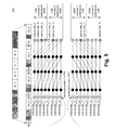
- FIG. 2A illustrates a block diagram of hierarchical statistically multiplexed counters 200 in accordance with some embodiments of the present invention.
- the hierarchical statistically multiplexed counters 200 includes a plurality of levels of statistically multiplexed counters 205 a , 205 b (collectively, 205 ). Each of the plurality of levels of statistically multiplexed counters 205 is similarly configured as the above-described statistically multiplexed counters 100 .
- the hierarchical statistically multiplexed counters 200 includes two levels: level 1 counters 205 a and level 2 counter 205 b .
- the hierarchical statistically multiplexed counters 200 can include more than two levels, but each level adds to the overhead of the mapping bits.
- each level 205 There can be the same or different number of counters on each level 205 .
- the width of each subcounter is the same and the width of each base counter is the same.
- widths of subcounters across levels 205 can be the same or different.
- widths of base counters across levels 205 can be same or different.
- each level 1 base counter is r 1 bits wide
- each level 1 subcounter is k 1 bits wide
- each level 2 base counter is r 2 bits wide
- each level 2 subcounter is k 2 bits wide.
- level 1 When a row overflow occurs in level 1 , counters in level 2 are used. For example, an event comes in to the level 1 counter C. Assume the level 1 counter C overflows unless another brick is assigned to the level 1 counter C. However, if there are no available bricks left in the corresponding row, then the level 1 counter C will wrap around and a count is added to the level 2 counter C.
- the counters in the same row in level 1 are shuffled into different rows in level 2 , as shown in FIG. 2A .
- P 1 *P 2 counters are statistically multiplexed.
- a randomization of the shuffle can be a bit reverse of the counter identifier of a counter.
- a randomization of the shuffle can be based on a hash function.
- a randomization of the shuffle is a bit arrangement in another order.
- the total count for counter C is level_ 2 _ctr* 2 (r1+k1) +level_ 1 _ctr, wherein level_ 1 _ctr and level_ 2 _ctr are the values of the level 1 counter C and the level 2 counter C, respectively.
- the hierarchical statistically multiplexed counters 200 can be used with an overflow FIFO 210 , as illustrated in FIG. 2B .
- An exemplary overflow FIFO is discussed in U.S. patent application Ser. No. 14/302,343, entitled “Counter with Overflow FIFO and a Method Thereof,” filed Jun. 11, 2014, which is hereby incorporated by reference in its entirety.
- the overflow FIFO 210 is used.
- the overflow FIFO 210 can be stored in SRAM. Alternatively, the overflow FIFO 210 is fixed function hardware.
- the overflow FIFO 210 is typically shared and used by all N counters in the highest level.
- the overflow FIFO 210 When rows start to overflow in the highest level (e.g., level 2 in FIG. 2B ), the overflow FIFO 210 will store the associated counter identifiers of all counters that are overflowing. Typically, as soon as any of the level 2 counters 205 b starts overflowing, the associated counter identification of an overflowed counter and an overflow width are pushed into the overflow FIFO 210 . An interrupt is sent to a CPU to read the overflow FIFO 210 and to read and to reset or clear the overflowed counter (e.g., counter C in FIG. 2B ) in each level.
- the overflow FIFO 210 will store the associated counter identifiers of all counters that are overflowing.
- the associated counter identification of an overflowed counter and an overflow width are pushed into the overflow FIFO 210 .
- An interrupt is sent to a CPU to read the overflow FIFO 210 and to read and to reset or clear the overflowed counter
- FIG. 3A illustrates a flow diagram 300 of updating a counter in accordance with some embodiments of the present invention.
- the hierarchical statistically multiplexed counters includes two levels.
- counter C includes a current value of init_value and is to be updated with a value of B, which can result in no overflows, a level 1 overflow, or both a level 1 overflow and a level 2 overflow.
- Counter C is to be incremented with value B (step 305 ). It is determined whether there is a level 1 row overflow of the row that counter C is in (step 310 ). If it is determined that there is no level 1 row overflow at the step 310 , then the level 1 counter C is incremented (step 315 ). The level 1 counter C is expanded by concatenating with another available subcounter if necessary. And, the counter update process is done. After updating, the level 1 counter value is level_ 1 _init_value+B.
- the level 1 counter C is incremented with a wrap around and is shrunk if it is initially using more than one subcounter (step 320 ).
- a counter is shrunk, one or more subcounters are freed up for reallocation. The shrinkage enables other counters in the same row to extend themselves or that counter to adapt itself.
- step 325 it is determined if there is a level 2 row overflow of the row that counter C is in (step 325 ). If it is determined that there is no level 2 row overflow at the step 325 , then the level 2 counter C is incremented (step 330 ). The level 2 counter C is expanded by concatenating with another available subcounter if necessary.
- the level 2 counter C is incremented with a wrap around and is shrunk by removing one or more subcounters (step 335 ).
- the counter identifier of counter C and the overflow width are pushed into the overflow FIFO (step 340 ).
- the level 1 counter value is (level_ 1 _init_value+B) %2 (r1+k1) . If there is no level 2 overflow, then the level 2 counter value is level_ 2 _init_value+(level_ 1 _init_value+B)>>(r 1 +k 1 ). If there is a level 2 overflow, then the level 2 counter value is (level_ 2 _init_value+(level_ 1 _init_value+B)>>(r 1 +k 1 ))%2 (r2+k2) , while the counter identifier of the overflowed counter and the overflow width are pushed into the overflow FIFO.
- FIG. 3B illustrates a flow diagram 350 of updating a counter in a hierarchy of J levels.
- FIG. 4 illustrates a counter update example 400 in accordance with some embodiments of the present invention.
- the level 1 counter C wraps around and shrinks to one brick, leaving 8′h00.
- the level 2 counter C wraps around and shrinks to one brick, leaving 8′h0F, while the counter identifier of counter C and the overflow width of 12 bits is pushed to the overflow FIFO.
- the final counter value can be reconstructed as: overflow FIFO value+level 2 value+level 1 value.
- the overflow FIFO value is sum[2 (r1+k1+overflow _ width) ] for all occurrences of the counter identification in the overflow FIFO.
- the level 2 value is level_ 2 _ctr*2 (r1+k1) , where level_ 2 _ctr is the value of the level 2 counter.
- the level 1 value is level_ 1 _ctr, which is the value of the level 1 counter.
- the overhead in each row includes a S-bit mapping of subcounters to base counters.
- a 8-bit mapping is used. Assume the S-bit mapping is 8′b10010101, where a “1” in the mapping delimits counter boundary.
- the 8′b10010101 mapping indicates that the base counter ctr_0 is associated with subcounter 0 (based on 0 th bit in the mapping), the base counter ctr_1 is associated with subcounter 1 and subcounter 2 (based on 1 st and 2 nd bits in the mapping), the base counter ctr_2 is associated with subcounter 3 and subcounter 4 (based on 3 rd and 4 th bits in the mapping), and the base counter ctr_3 is associated with subcounter 5 , subcounter 6 and subcounter 7 (based on 5 th , 6 th and 7 th bits in the mapping).
- the 8′b10010101 mapping indicates the amount shifting of each subcounter. Based on this shifting, the 7 th bit (or 75 th subcounter) can potentially be shifted a lot, which is hardware intensive. In some embodiments, to minimize the amount of shifting, a shifting and twisting technique is used.
- FIG. 5 illustrates an example 500 of mapping subcounters to base counters in accordance with some embodiments of the present invention.
- a restriction is placed on how the subcounters are mapped to the base counters.
- the restriction is that each base counter is assigned at least one subcounter but no more than a predetermined number of subcounters.
- each base counter is assigned q subcounters, where 1 ⁇ q ⁇ 4. As such, a second mechanism of row overflow is introduced, when a counter needs to be expanded beyond the maximum allowed number of subcounters.
- a shift network includes a lower shift network and an upper shift network.
- the base counters are divided between the lower shift network and the upper shift network.
- the lower base counters are associated with the lower shift network to shift the subcounters up.
- the upper base counters are associated with the upper shift network to shift the subcounters down.
- a subcounter is typically shifted up if its rank is less than P/2, and a subcounter is typically shifted down if its rank is greater than or equal to P/2.
- the S-bit mapping is rather 8′0010_1101, as shown in FIG. 5 .
- the S-bit mapping is read from the right for lower P/2 base counters and is read from the left for the upper P/2 base counters.
- “ 1 ” in the mapping delimits counter boundary.
- the 0 th bit in this mapping indicates that subcounter 0 is mapped to base counter ctr_ 0 .
- the 2 nd bit in this mapping indicates that subcounters 1 and 2 are mapped to base counter ctr_ 1 . Since there are already two counters, for the other (upper) two counters, the reading is from the left.
- the 3 rd bit in this mapping indicates that subcounter 3 and subcounter 4 are mapped to base counter ctr_ 2 .
- the 5 th bit in this mapping indicates that subcounters 5 , 6 and 7 are mapped to base counter ctr_ 3 .
- the counters are extended to full width such that the full range of shifting is reduced. In example 500 , an entire layer of shifting is eliminated by mirroring the shift logic.
- a subcounter is associated with the lower shift network if its rank is less than P/2, and a subcounter is associated with the upper shift network if its rank is ⁇ P/2.
- the lower shift network shifts lower subcounter i up by 4*rank(i)+dist(i) ⁇ i, where rank(i) is the number of 1 's, starting from the least significant bit, in the lower bits, and dist(i) is the number of 0 's since the last bit of 1 from the lower bits.
- the upper shift network shifts upper subcounter i down by a slightly different equation, namely 4*reverse_rank(i)+reverse_dist(i) ⁇ (S ⁇ 1 ⁇ i), wherein reverse_rank(i) is the number of 1 's, starting from the most significant bit, in the upper bits, and reverse_dist(i) is the number of 0 's since the last bit of 1 from the upper bits.
- the upper shift network mirrors significance of subscounters versus the lower shift network.
- subcounter_ 7 is applied to least significant position of all counter 3 extensions and subcounter_ 5 is applied to most significant position of all counter 3 extensions.
- the hardware is more complex. With twisting, shifting is reduced by half. In some embodiments, at least one layer of shifting is eliminated. Hardware shifting is improved by aligning at both ends and expanding towards the center. Further, as illustrated in FIG. 5 , the dotted lines are always inactive and can be further optimized, thereby reducing hardware implementation cost.
- EPS is 654.8 MPPS
- the CPU read interval is ⁇ 2.32 seconds.
- the CPU read interval is on the order of one minute.
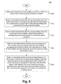
- FIG. 6 illustrates a method of updating a counter in a counter architecture 600 in accordance with some embodiments of the present invention.
- the counter architecture includes a hierarchy of levels of statistically multiplexed counters.
- the current level is the lowest level in the hierarchy of levels.
- each level below the current level is processed by using a first routine and the current level is processed by using a second routine.
- the first routine includes incrementing the counter in the corresponding level and shrinking the counter in the corresponding level.
- the second routine includes incrementing the counter in the corresponding level, wherein a size of the counter in the corresponding level is expanded if necessary.
- a step 615 based on the determination that the corresponding row in the current level does overflow, it is determined whether a corresponding row of the counter in a next level above overflows.
- each level below the next level above is processed by using the first routine and the next level above is processed by using the second routine.
- the first routine includes incrementing the counter in the corresponding level and shrinking the counter in the corresponding level; and, the second routine includes incrementing the counter in the corresponding level, wherein a size of the counter in the corresponding level is expanded if necessary.
- steps, starting from the step 615 are repeated; otherwise, when the next level above is the highest level in the hierarchy of levels, the next level above and each level below the next level above is processed by using the first routine and an overflow queue is updated.
- the first routine includes incrementing the counter in the corresponding level and shrinking the counter in the corresponding level.
- the overflow queue updated by pushing a counter identifier of the counter and an overflow width into the overflow queue.
- An interrupt is sent to the CPU to read data at in the overflow queue for processing.
- a wrap-around counter is identified by the data in the overflow queue.
- a value stored of the identified counter in each level is read and cleared. Based on these values, a final counter value can be calculated.
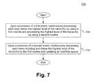
- FIG. 7 illustrates another method of updating the counter in the counter architecture 700 in accordance with some embodiments of the present invention.
- a step 705 upon occurrence of a first event, each level below the highest level of the hierarchy is continuously processed by using a first routine and the highest level of the hierarchy is processed by using a second routine.
- the first event is a row overflow in each level below the highest level of the hierarchy but no row overflow in the highest level of the hierarchy.
- the first routine includes incrementing the counter in the corresponding level and shrinking the counter in the corresponding level.
- the second routine includes incrementing the counter in the corresponding level.
- the incrementing the counter includes expanding a size of the counter in the corresponding level.
- each level including and below the highest level of the hierarchy is continuously processed by the first routine and an overflow queue is updated.
- the second event is a row overflow in each level including and below the highest level of the hierarchy.
- the first routine includes incrementing the counter in the corresponding level and shrinking the counter in the corresponding level.
- the overflow queue is updated by pushing a counter identifier of the counter and an overflow width into the overflow queue.
- the counter architecture which includes hierarchical statistically multiplexed counters and an overflow FIFO, is typically implemented in a high speed network device, such as a network switch.
- the counters are stored in an on-chip SRAM memory, using two banks of memory. Exemplary counters and memory banks are discussed in U.S. patent application Ser. No. 14/289,533, entitled “Method and Apparatus for Flexible and Efficient Analytics in a Network Switch,” filed May 28, 2014, which is hereby incorporated by reference in its entirety.
- This counter architecture is able to advantageously extend counter life by orders of magnitude, as illustrated in the above comparisons.
Abstract
Description
Claims (14)
Priority Applications (9)
| Application Number | Priority Date | Filing Date | Title |
|---|---|---|---|
| US14/302,351 US9413357B2 (en) | 2014-06-11 | 2014-06-11 | Hierarchical statistically multiplexed counters and a method thereof |
| TW104112176A TWI656476B (en) | 2014-06-11 | 2015-04-16 | Hierarchical statistical multiplex counter and its architecture, method, and network device including the counter architecture |
| CN201510320187.8A CN105320493B (en) | 2014-06-11 | 2015-06-11 | Counting device |
| US15/202,428 US10038448B2 (en) | 2014-06-11 | 2016-07-05 | Hierarchical statisically multiplexed counters and a method thereof |
| HK16108891.5A HK1220787A1 (en) | 2014-06-11 | 2016-07-26 | Hierarchical statistically multiplexed counters and a method thereof |
| US16/019,780 US10840912B2 (en) | 2014-06-11 | 2018-06-27 | Hierarchical statistically multiplexed counters and a method thereof |
| US17/070,771 US11277138B2 (en) | 2014-06-11 | 2020-10-14 | Hierarchical statistically multiplexed counters and a method thereof |
| US17/591,546 US11843378B2 (en) | 2014-06-11 | 2022-02-02 | Hierarchical statistically multiplexed counters and a method thereof |
| US18/500,091 US20240063800A1 (en) | 2014-06-11 | 2023-11-01 | Hierarchical statisically multiplexed counters and a method thereof |
Applications Claiming Priority (1)
| Application Number | Priority Date | Filing Date | Title |
|---|---|---|---|
| US14/302,351 US9413357B2 (en) | 2014-06-11 | 2014-06-11 | Hierarchical statistically multiplexed counters and a method thereof |
Related Child Applications (1)
| Application Number | Title | Priority Date | Filing Date |
|---|---|---|---|
| US15/202,428 Division US10038448B2 (en) | 2014-06-11 | 2016-07-05 | Hierarchical statisically multiplexed counters and a method thereof |
Publications (2)
| Publication Number | Publication Date |
|---|---|
| US20150365355A1 US20150365355A1 (en) | 2015-12-17 |
| US9413357B2 true US9413357B2 (en) | 2016-08-09 |
Family
ID=54837141
Family Applications (6)
| Application Number | Title | Priority Date | Filing Date |
|---|---|---|---|
| US14/302,351 Active 2035-03-10 US9413357B2 (en) | 2014-06-11 | 2014-06-11 | Hierarchical statistically multiplexed counters and a method thereof |
| US15/202,428 Active 2035-01-08 US10038448B2 (en) | 2014-06-11 | 2016-07-05 | Hierarchical statisically multiplexed counters and a method thereof |
| US16/019,780 Active 2034-07-27 US10840912B2 (en) | 2014-06-11 | 2018-06-27 | Hierarchical statistically multiplexed counters and a method thereof |
| US17/070,771 Active US11277138B2 (en) | 2014-06-11 | 2020-10-14 | Hierarchical statistically multiplexed counters and a method thereof |
| US17/591,546 Active US11843378B2 (en) | 2014-06-11 | 2022-02-02 | Hierarchical statistically multiplexed counters and a method thereof |
| US18/500,091 Pending US20240063800A1 (en) | 2014-06-11 | 2023-11-01 | Hierarchical statisically multiplexed counters and a method thereof |
Family Applications After (5)
| Application Number | Title | Priority Date | Filing Date |
|---|---|---|---|
| US15/202,428 Active 2035-01-08 US10038448B2 (en) | 2014-06-11 | 2016-07-05 | Hierarchical statisically multiplexed counters and a method thereof |
| US16/019,780 Active 2034-07-27 US10840912B2 (en) | 2014-06-11 | 2018-06-27 | Hierarchical statistically multiplexed counters and a method thereof |
| US17/070,771 Active US11277138B2 (en) | 2014-06-11 | 2020-10-14 | Hierarchical statistically multiplexed counters and a method thereof |
| US17/591,546 Active US11843378B2 (en) | 2014-06-11 | 2022-02-02 | Hierarchical statistically multiplexed counters and a method thereof |
| US18/500,091 Pending US20240063800A1 (en) | 2014-06-11 | 2023-11-01 | Hierarchical statisically multiplexed counters and a method thereof |
Country Status (4)
| Country | Link |
|---|---|
| US (6) | US9413357B2 (en) |
| CN (1) | CN105320493B (en) |
| HK (1) | HK1220787A1 (en) |
| TW (1) | TWI656476B (en) |
Families Citing this family (3)
| Publication number | Priority date | Publication date | Assignee | Title |
|---|---|---|---|---|
| US9798900B2 (en) * | 2015-03-26 | 2017-10-24 | Intel Corporation | Flexible counter system for memory protection |
| US10228852B1 (en) * | 2016-03-25 | 2019-03-12 | Amazon Technologies, Inc. | Multi-stage counters |
| US10528485B2 (en) | 2016-09-30 | 2020-01-07 | Intel Corporation | Method and apparatus for sharing security metadata memory space |
Citations (11)
| Publication number | Priority date | Publication date | Assignee | Title |
|---|---|---|---|---|
| US5809174A (en) | 1993-04-13 | 1998-09-15 | C-Cube Microsystems | Decompression processor for video applications |
| US6687325B1 (en) * | 1999-06-23 | 2004-02-03 | Intel Corporation | Counter with non-uniform digit base |
| US6895070B2 (en) * | 2001-12-28 | 2005-05-17 | Sharp Kabushiki Kaisha | Counter circuit |
| US6944256B2 (en) * | 2003-04-25 | 2005-09-13 | Alcatel Ip Networks, Inc. | Optimizing use of statistics counters |
| US7085229B1 (en) | 2001-10-24 | 2006-08-01 | Cisco Technology, Inc. | Scheduling assist for data networking packet dequeuing in a parallel 1-D systolic array system |
| US7627870B1 (en) | 2001-04-28 | 2009-12-01 | Cisco Technology, Inc. | Method and apparatus for a data structure comprising a hierarchy of queues or linked list data structures |
| US20110103504A1 (en) * | 2009-10-30 | 2011-05-05 | Futurewei Technologies, Inc. | System and Method for User Specific Antenna Down Tilt in Wireless Cellular Networks |
| US8064567B2 (en) * | 2006-10-26 | 2011-11-22 | Rohde & Schwarz Gmbh & Co. Kg | Method and device for the incremention of counter statuses stored in memory cells of a memory |
| US8189732B1 (en) * | 2010-11-17 | 2012-05-29 | Atmel Corporation | Non-volatile memory counter |
| US8345816B1 (en) * | 2011-12-06 | 2013-01-01 | International Business Machines Corporation | RAM-based event counters using transposition |
| US8761332B2 (en) * | 2012-09-24 | 2014-06-24 | Texas Instruments Incorporated | Dynamic prescaling counters |
Family Cites Families (24)
| Publication number | Priority date | Publication date | Assignee | Title |
|---|---|---|---|---|
| US3064567A (en) | 1961-04-17 | 1962-11-20 | Mcbee Company Ltd | Postage meter base |
| US6157695A (en) * | 1998-10-26 | 2000-12-05 | Microchip Technology, Inc. | Counter for performing multiple counts and method thereof |
| US6831917B1 (en) | 2000-05-10 | 2004-12-14 | Cisco Technology, Inc. | Network address translation for multicast virtual sourcing |
| US6922456B2 (en) * | 2002-03-25 | 2005-07-26 | Hewlett-Packard Development Company, L.P. | Counter system and method |
| US7685436B2 (en) | 2003-10-02 | 2010-03-23 | Itt Manufacturing Enterprises, Inc. | System and method for a secure I/O interface |
| US7085907B2 (en) | 2004-02-17 | 2006-08-01 | International Business Machines Corporation | Dynamic reconfiguration of memory in a multi-cluster storage control unit |
| US7716460B2 (en) * | 2006-09-29 | 2010-05-11 | Qualcomm Incorporated | Effective use of a BHT in processor having variable length instruction set execution modes |
| US8054744B1 (en) | 2007-10-25 | 2011-11-08 | Marvell International Ltd. | Methods and apparatus for flow classification and flow measurement |
| US20110103540A1 (en) * | 2009-10-29 | 2011-05-05 | Wassermann Gary M | Multiple base counter representation |
| US20120331088A1 (en) | 2011-06-01 | 2012-12-27 | Security First Corp. | Systems and methods for secure distributed storage |
| US9021206B2 (en) * | 2011-08-25 | 2015-04-28 | International Business Machines Corporation | Use of cache statistics to ration cache hierarchy access |
| US8711860B2 (en) | 2011-12-22 | 2014-04-29 | Telefonaktiebolaget L M Ericsson (Publ) | Controller for flexible and extensible flow processing in software-defined networks |
| US9225635B2 (en) | 2012-04-10 | 2015-12-29 | International Business Machines Corporation | Switch routing table utilizing software defined network (SDN) controller programmed route segregation and prioritization |
| US9258277B1 (en) | 2012-06-27 | 2016-02-09 | Juniper Networks, Inc. | Decentralized packet dispatch in network devices |
| US20140153443A1 (en) | 2012-11-30 | 2014-06-05 | International Business Machines Corporation | Per-Address Spanning Tree Networks |
| US9417910B2 (en) * | 2012-12-20 | 2016-08-16 | Oracle International Corporation | System and method for implementing shared probabilistic counters storing update probability values |
| US9183048B2 (en) * | 2012-12-20 | 2015-11-10 | Oracle International Corporation | System and method for implementing scalable contention-adaptive statistics counters |
| US20140369363A1 (en) | 2013-06-18 | 2014-12-18 | Xpliant, Inc. | Apparatus and Method for Uniquely Enumerating Paths in a Parse Tree |
| CN103347013B (en) | 2013-06-21 | 2016-02-10 | 北京邮电大学 | A kind of OpenFlow network system and method strengthening programmability |
| US9590914B2 (en) | 2013-11-05 | 2017-03-07 | Cisco Technology, Inc. | Randomized per-packet port channel load balancing |
| US9363178B2 (en) | 2013-12-18 | 2016-06-07 | Telefonaktiebolaget L M Ericsson (Publ) | Method, apparatus, and system for supporting flexible lookup keys in software-defined networks |
| US9620213B2 (en) | 2013-12-27 | 2017-04-11 | Cavium, Inc. | Method and system for reconfigurable parallel lookups using multiple shared memories |
| US9379963B2 (en) | 2013-12-30 | 2016-06-28 | Cavium, Inc. | Apparatus and method of generating lookups and making decisions for packet modifying and forwarding in a software-defined network engine |
| CN104010049B (en) | 2014-04-30 | 2017-10-03 | 易云捷讯科技(北京)股份有限公司 | Ethernet ip message encapsulating method and Network Isolation and DHCP implementation methods based on SDN |
-
2014
- 2014-06-11 US US14/302,351 patent/US9413357B2/en active Active
-
2015
- 2015-04-16 TW TW104112176A patent/TWI656476B/en active
- 2015-06-11 CN CN201510320187.8A patent/CN105320493B/en active Active
-
2016
- 2016-07-05 US US15/202,428 patent/US10038448B2/en active Active
- 2016-07-26 HK HK16108891.5A patent/HK1220787A1/en unknown
-
2018
- 2018-06-27 US US16/019,780 patent/US10840912B2/en active Active
-
2020
- 2020-10-14 US US17/070,771 patent/US11277138B2/en active Active
-
2022
- 2022-02-02 US US17/591,546 patent/US11843378B2/en active Active
-
2023
- 2023-11-01 US US18/500,091 patent/US20240063800A1/en active Pending
Patent Citations (11)
| Publication number | Priority date | Publication date | Assignee | Title |
|---|---|---|---|---|
| US5809174A (en) | 1993-04-13 | 1998-09-15 | C-Cube Microsystems | Decompression processor for video applications |
| US6687325B1 (en) * | 1999-06-23 | 2004-02-03 | Intel Corporation | Counter with non-uniform digit base |
| US7627870B1 (en) | 2001-04-28 | 2009-12-01 | Cisco Technology, Inc. | Method and apparatus for a data structure comprising a hierarchy of queues or linked list data structures |
| US7085229B1 (en) | 2001-10-24 | 2006-08-01 | Cisco Technology, Inc. | Scheduling assist for data networking packet dequeuing in a parallel 1-D systolic array system |
| US6895070B2 (en) * | 2001-12-28 | 2005-05-17 | Sharp Kabushiki Kaisha | Counter circuit |
| US6944256B2 (en) * | 2003-04-25 | 2005-09-13 | Alcatel Ip Networks, Inc. | Optimizing use of statistics counters |
| US8064567B2 (en) * | 2006-10-26 | 2011-11-22 | Rohde & Schwarz Gmbh & Co. Kg | Method and device for the incremention of counter statuses stored in memory cells of a memory |
| US20110103504A1 (en) * | 2009-10-30 | 2011-05-05 | Futurewei Technologies, Inc. | System and Method for User Specific Antenna Down Tilt in Wireless Cellular Networks |
| US8189732B1 (en) * | 2010-11-17 | 2012-05-29 | Atmel Corporation | Non-volatile memory counter |
| US8345816B1 (en) * | 2011-12-06 | 2013-01-01 | International Business Machines Corporation | RAM-based event counters using transposition |
| US8761332B2 (en) * | 2012-09-24 | 2014-06-24 | Texas Instruments Incorporated | Dynamic prescaling counters |
Also Published As
| Publication number | Publication date |
|---|---|
| US11843378B2 (en) | 2023-12-12 |
| US20180323789A1 (en) | 2018-11-08 |
| HK1220787A1 (en) | 2017-05-12 |
| US20160315622A1 (en) | 2016-10-27 |
| CN105320493A (en) | 2016-02-10 |
| US20210058087A1 (en) | 2021-02-25 |
| CN105320493B (en) | 2019-12-17 |
| TWI656476B (en) | 2019-04-11 |
| US10038448B2 (en) | 2018-07-31 |
| US11277138B2 (en) | 2022-03-15 |
| US20220158641A1 (en) | 2022-05-19 |
| TW201606642A (en) | 2016-02-16 |
| US20150365355A1 (en) | 2015-12-17 |
| US10840912B2 (en) | 2020-11-17 |
| US20240063800A1 (en) | 2024-02-22 |
Similar Documents
| Publication | Publication Date | Title |
|---|---|---|
| US11843378B2 (en) | Hierarchical statistically multiplexed counters and a method thereof | |
| JP6373336B2 (en) | Sanitize recognition DRAM controller | |
| Cannon et al. | Implementation and analysis of the Todd-Coxeter algorithm | |
| US10620861B2 (en) | Retrieve data block from determined devices | |
| US7536488B2 (en) | Buffer controller and management method thereof | |
| JP2004194319A (en) | Apparatus and method for using completely configurable memory multi-stage pipeline logic and embedded type processor to realize multi-bit trie algorithm network search engine | |
| US9055011B2 (en) | Methods and apparatus for linked-list circular buffer management | |
| US20090106500A1 (en) | Method and Apparatus for Managing Buffers in a Data Processing System | |
| JP2005198285A (en) | Apparatus and method using hashing for efficiently implementing ip lookup solution in hardware | |
| US10007615B1 (en) | Methods and apparatus for performing fast caching | |
| CN105446897B (en) | Cache logic, memory system and method for generating cache address | |
| US10254988B2 (en) | Memory device write based on mapping | |
| US20030121030A1 (en) | Method for implementing dual link list structure to enable fast link-list pointer updates | |
| US20030167383A1 (en) | System and method for memory interleaving using cell map with entry grouping for higher-way interleaving | |
| US11361811B2 (en) | Method and circuit for protecting a DRAM memory device from the row hammer effect | |
| US9852074B2 (en) | Cache-optimized hash table data structure | |
| US10261694B2 (en) | Data storage method and system | |
| CN113419973A (en) | Message forwarding method and device | |
| CN107861819B (en) | Cache group load balancing method and device and computer readable storage medium | |
| US6687786B1 (en) | Automated free entry management for content-addressable memory using virtual page pre-fetch | |
| CN107341113B (en) | Cache compression method and device | |
| CN108647289B (en) | Hash table building method based on valley Hash and bloom filter | |
| US20100122039A1 (en) | Memory Systems and Accessing Methods | |
| US20150365339A1 (en) | Counter with overflow fifo and a method thereof | |
| CN110334251B (en) | Element sequence generation method for effectively solving rehash conflict |
Legal Events
| Date | Code | Title | Description |
|---|---|---|---|
| AS | Assignment |
Owner name: XPLIANT, INC., CALIFORNIA Free format text: ASSIGNMENT OF ASSIGNORS INTEREST;ASSIGNORS:WANG, WEIHUANG;SCHMIDT, GERALD;ATLURI, SRINATH;AND OTHERS;REEL/FRAME:033286/0915 Effective date: 20140707 |
|
| AS | Assignment |
Owner name: CAVIUM, INC., CALIFORNIA Free format text: ASSIGNMENT OF ASSIGNORS INTEREST;ASSIGNOR:CAVIUM NETWORKS LLC;REEL/FRAME:038040/0251 Effective date: 20160308 Owner name: CAVIUM NETWORKS LLC, CALIFORNIA Free format text: MERGER;ASSIGNOR:XPLIANT, INC.;REEL/FRAME:038039/0328 Effective date: 20150429 |
|
| STCF | Information on status: patent grant |
Free format text: PATENTED CASE |
|
| AS | Assignment |
Owner name: JPMORGAN CHASE BANK, N.A., AS COLLATERAL AGENT, ILLINOIS Free format text: SECURITY AGREEMENT;ASSIGNORS:CAVIUM, INC.;CAVIUM NETWORKS LLC;REEL/FRAME:039715/0449 Effective date: 20160816 Owner name: JPMORGAN CHASE BANK, N.A., AS COLLATERAL AGENT, IL Free format text: SECURITY AGREEMENT;ASSIGNORS:CAVIUM, INC.;CAVIUM NETWORKS LLC;REEL/FRAME:039715/0449 Effective date: 20160816 |
|
| AS | Assignment |
Owner name: CAVIUM, INC, CALIFORNIA Free format text: RELEASE BY SECURED PARTY;ASSIGNOR:JP MORGAN CHASE BANK, N.A., AS COLLATERAL AGENT;REEL/FRAME:046496/0001 Effective date: 20180706 Owner name: QLOGIC CORPORATION, CALIFORNIA Free format text: RELEASE BY SECURED PARTY;ASSIGNOR:JP MORGAN CHASE BANK, N.A., AS COLLATERAL AGENT;REEL/FRAME:046496/0001 Effective date: 20180706 Owner name: CAVIUM NETWORKS LLC, CALIFORNIA Free format text: RELEASE BY SECURED PARTY;ASSIGNOR:JP MORGAN CHASE BANK, N.A., AS COLLATERAL AGENT;REEL/FRAME:046496/0001 Effective date: 20180706 |
|
| AS | Assignment |
Owner name: CAVIUM, LLC, CALIFORNIA Free format text: CHANGE OF NAME;ASSIGNOR:CAVIUM, INC.;REEL/FRAME:047577/0653 Effective date: 20180924 |
|
| MAFP | Maintenance fee payment |
Free format text: PAYMENT OF MAINTENANCE FEE, 4TH YEAR, LARGE ENTITY (ORIGINAL EVENT CODE: M1551); ENTITY STATUS OF PATENT OWNER: LARGE ENTITY Year of fee payment: 4 |
|
| AS | Assignment |
Owner name: CAVIUM INTERNATIONAL, CAYMAN ISLANDS Free format text: ASSIGNMENT OF ASSIGNORS INTEREST;ASSIGNOR:CAVIUM, LLC;REEL/FRAME:051948/0807 Effective date: 20191231 |
|
| AS | Assignment |
Owner name: MARVELL ASIA PTE, LTD., SINGAPORE Free format text: ASSIGNMENT OF ASSIGNORS INTEREST;ASSIGNOR:CAVIUM INTERNATIONAL;REEL/FRAME:053179/0320 Effective date: 20191231 |
|
| MAFP | Maintenance fee payment |
Free format text: PAYMENT OF MAINTENANCE FEE, 8TH YEAR, LARGE ENTITY (ORIGINAL EVENT CODE: M1552); ENTITY STATUS OF PATENT OWNER: LARGE ENTITY Year of fee payment: 8 |