US9410755B2 - Locking front sight for a firearm and firearm with locking front sight - Google Patents
Locking front sight for a firearm and firearm with locking front sight Download PDFInfo
- Publication number
- US9410755B2 US9410755B2 US13/524,591 US201213524591A US9410755B2 US 9410755 B2 US9410755 B2 US 9410755B2 US 201213524591 A US201213524591 A US 201213524591A US 9410755 B2 US9410755 B2 US 9410755B2
- Authority
- US
- United States
- Prior art keywords
- tower
- mounting block
- front sight
- spring biased
- locking mechanism
- Prior art date
- Legal status (The legal status is an assumption and is not a legal conclusion. Google has not performed a legal analysis and makes no representation as to the accuracy of the status listed.)
- Active
Links
- 230000007246 mechanism Effects 0.000 claims abstract description 29
- 230000004044 response Effects 0.000 claims abstract description 5
- 238000004891 communication Methods 0.000 claims description 9
- 239000012530 fluid Substances 0.000 claims description 9
- 230000001351 cycling effect Effects 0.000 description 10
- 230000008878 coupling Effects 0.000 description 5
- 238000010168 coupling process Methods 0.000 description 5
- 238000005859 coupling reaction Methods 0.000 description 5
- 230000008901 benefit Effects 0.000 description 2
- 230000000295 complement effect Effects 0.000 description 2
- 210000003811 finger Anatomy 0.000 description 2
- 238000000034 method Methods 0.000 description 2
- 210000003813 thumb Anatomy 0.000 description 2
- OKTJSMMVPCPJKN-UHFFFAOYSA-N Carbon Chemical compound [C] OKTJSMMVPCPJKN-UHFFFAOYSA-N 0.000 description 1
- 229910052799 carbon Inorganic materials 0.000 description 1
- 210000005069 ears Anatomy 0.000 description 1
- 239000000463 material Substances 0.000 description 1
- 238000012986 modification Methods 0.000 description 1
- 230000004048 modification Effects 0.000 description 1
- 230000003287 optical effect Effects 0.000 description 1
- 230000001105 regulatory effect Effects 0.000 description 1
- 230000007704 transition Effects 0.000 description 1
Images


Classifications
-
- F—MECHANICAL ENGINEERING; LIGHTING; HEATING; WEAPONS; BLASTING
- F41—WEAPONS
- F41A—FUNCTIONAL FEATURES OR DETAILS COMMON TO BOTH SMALLARMS AND ORDNANCE, e.g. CANNONS; MOUNTINGS FOR SMALLARMS OR ORDNANCE
- F41A5/00—Mechanisms or systems operated by propellant charge energy for automatically opening the lock
- F41A5/18—Mechanisms or systems operated by propellant charge energy for automatically opening the lock gas-operated
- F41A5/26—Arrangements or systems for bleeding the gas from the barrel
- F41A5/28—Adjustable systems
-
- F—MECHANICAL ENGINEERING; LIGHTING; HEATING; WEAPONS; BLASTING
- F41—WEAPONS
- F41A—FUNCTIONAL FEATURES OR DETAILS COMMON TO BOTH SMALLARMS AND ORDNANCE, e.g. CANNONS; MOUNTINGS FOR SMALLARMS OR ORDNANCE
- F41A5/00—Mechanisms or systems operated by propellant charge energy for automatically opening the lock
- F41A5/18—Mechanisms or systems operated by propellant charge energy for automatically opening the lock gas-operated
-
- F—MECHANICAL ENGINEERING; LIGHTING; HEATING; WEAPONS; BLASTING
- F41—WEAPONS
- F41G—WEAPON SIGHTS; AIMING
- F41G1/00—Sighting devices
-
- F—MECHANICAL ENGINEERING; LIGHTING; HEATING; WEAPONS; BLASTING
- F41—WEAPONS
- F41G—WEAPON SIGHTS; AIMING
- F41G1/00—Sighting devices
- F41G1/02—Foresights
-
- F—MECHANICAL ENGINEERING; LIGHTING; HEATING; WEAPONS; BLASTING
- F41—WEAPONS
- F41G—WEAPON SIGHTS; AIMING
- F41G1/00—Sighting devices
- F41G1/02—Foresights
- F41G1/033—Foresights adjustable
Definitions
- Various embodiments of the present invention relate generally to a rifle or firearm and in particular, a gas regulator for a firearm. Still other embodiments relate generally to a rifle or firearm and in particular, a locking sight for a firearm.
- Folding or collapsible sights are desirable for weapons in that the same allows the sight to transition from a first folded or stowed position to a second extended or deployed position.
- the first folded or stowed position allows the sight to be configured or located in a position that does not interfere with an optical sighting system or accessory that is mounted to a rail of the weapon.
- folding or collapsible sights may be inadvertently moved from the deployed position. Accordingly, it is desirable to provide a folding or collapsible sight with a locking mechanism that prevents inadvertent movement of the sight
- a flash suppressor and/or a sound suppressor used with a firearm or rifle will increase the rate of fire or cycling of the firearm. This increase in cycling may also increase the wear rate of components of the firearm.
- variations in the types of ammunition used with rifle will also vary the cycling rate of the rifle and a rifle configured for use with one type of ammunition may cycle too fast when fired with another type of ammunition thus causing the aforementioned excessive wear to the components of the rifle.
- Non-limiting examples of different types of ammunition are 5.56 mm NATO ammunition and 223 Remington ammunition each of which may provide different cycling rates when fired from a rifle having the same gas port configuration in a gas impingement system. Still further there are reliability issues associated with higher cycling rates when ammunition is changed for example, round feeding may not occur or may occur improperly.
- a front sight for a weapon having: a mounting block; a tower pivotally mounted to the mounting block for movement between a first position and a second position; a first locking mechanism comprising a plurality of spring biased members for retaining the tower in the first position and the second position, the plurality of spring biased members being configured to allow movement of the tower between the first position and the second position in response to a force applied to the tower; and a second locking mechanism configured to lock the tower in the second position, wherein the second locking mechanism must be manually released before the tower can be moved from the second position to the first position.
- a rifle having: a mounting block configured to be coupled to a barrel of the rifle; a tower pivotally mounted to the mounting block for movement between a first position and a second position; a first locking mechanism comprising a plurality of spring biased members for retaining the tower in the first position and the second position, the plurality of spring biased members being configured to allow movement of the tower between the first position and the second position in response to a force applied to the tower; and a second locking mechanism configured to lock the tower in the second position, wherein the second locking mechanism must be manually released before the tower can be moved from the second position to the first position.
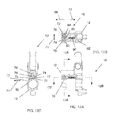
- FIG. 1 is an exploded perspective view of a locking front sight in accordance with an exemplary embodiment of the present invention
- FIG. 2 is a perspective view of a locking front sight in a first position in accordance with an exemplary embodiment of the present invention
- FIG. 2A is a left side view of the locking front sight in the first position
- FIG. 2B is a front view of the locking front sight in the first position
- FIG. 3 is a view along lines 3 - 3 of FIG. 2B ;
- FIG. 3A is a view along lines 3 A- 3 A of FIG. 2A ;
- FIG. 4 is a perspective view of a locking front sight in a second position in accordance with an exemplary embodiment of the present invention
- FIG. 4A is a left side view of the locking front sight in the second position
- FIG. 4B is a front view of the locking front sight in the second position
- FIG. 5 is a view along lines 5 - 5 of FIG. 4B ;
- FIG. 5A is a view along lines 5 A- 5 A of FIG. 4A ;
- FIGS. 6-9C are views of a locking front sight in accordance with an alternative exemplary embodiment of the present invention.
- FIGS. 10A and 10B illustrate the locking front sight of various embodiments of the present invention secured to an upper receiver of a firearm
- FIGS. 11-14D illustrate yet another alternative embodiment of the present invention.
- FIG. 15 illustrates a firearm according to various embodiments of the present invention.
- Disclosed herein is an apparatus, method and system for providing a locking sight for a rifle or firearm to provide various sight positions.
- the locking sight is a front sight of a firearm.
- the locking front sight 10 has a mounting block or gas block 12 that is mounted to an upper receiver of the firearm or weapon.
- a sight tower 14 is pivotally mounted to the mounting block or gas block 12 for movement between a first position FIGS. 1-3 and a second position FIGS. 4-5 .
- the sight tower 14 has a pair of tabs or ears 16 .
- a lower portion of the sight tower 14 is received within a pair of wall members 18 of the mounting block 12 .
- a pin or shaft 20 secures the lower portion of the sight tower 14 to the pair of wall members 18 .
- Pin or shaft 20 passes through openings in wall members 18 and the lower portion of the sight tower such that the sight tower can be moved between the first and second positions.
- a first locking mechanism 22 is provided.
- the first locking mechanism 22 is a plurality of spring biased members 24 that are received within complimentary openings 26 of the wall members 18 .
- the lower portion of the sight tower has a plurality of recessed features 28 on an exterior surface of the sight tower such that when the sight tower is in either the first or second position the plurality of spring biased members 24 extend outwardly away from wall member 18 such that a portion of each of the spring biased members is partially received within openings 26 and recessed features 28 such that the sight tower is locked in either the first position or the second position.
- the spring biased members 24 are a plurality of balls each being biased in a first direction 27 by a spring 29 .
- the spring biased members 24 are only located in one wall member 18 .
- the spring biased members 24 are located in both wall members 18 and are configured to engage complimentary openings or recessed features 28 on a surface of the sight tower.
- the openings or recessed features 28 are offset 90 degrees from each other to define the first position and the second position of the sight tower. Of course other orientations and configurations are contemplated.
- a force is applied to the sight tower such that the spring biased features are pushed back into the openings 24 of the wall member or members 18 and the tower can be repositioned from either the first or second position.
- the first lock mechanism 22 releasably retains the sight tower in either the first or second position.
- an applied force to the tower may be sufficient to overcome the biasing force applied to the spring biased members 24 and cause the tower to move between the first position and the second position, whether this is intentional or unintentional (e.g., sight tower inadvertently contacts a surface as opposed to a deliberate user applied force).
- a second locking mechanism 30 is provided.
- the second locking mechanism is configured to lock the tower in the second position, wherein the second locking mechanism must be manually released or disengaged before the tower can be moved from the second position to the first position.
- the second locking mechanism is a spring biased catch or member 32 having a tab portion or feature 34 that is configured to engage a slot or opening 36 of the mounting block when the sight tower is in the first position.
- the catch or member 32 is slidably mounted to the sight tower for movement in the direction of arrows 38 and 40 with respect to the sight tower 14 .
- the catch or member 32 is biased in the direction of arrow 38 by a spring 42 such that as the sight tower is rotated into the second position, tab or feature 34 of the catch or member 32 is received within the slot or opening 36 and the sight tower 14 is locked in the second position. Accordingly, the sight tower 14 cannot be moved from the second position to the first position unless catch or member 32 is moved upwardly in the direction of arrow 40 against the biasing force of the spring 42 .
- the catch or member is slidably mounted to the front end of the sight tower 14 and has a surface 46 that is configured to frictionally engage a user's finger or thumb in order to move the catch or member 32 in the direction of arrow 40 wherein the sight tower can be pivoted or rotated from the second or locked position towards the first position.
- the tab member or catch 32 is removed from the slot or opening 36 such that the tab member or catch 32 is no longer received within slot or opening 36 and the sight tower can be pivoted from the second position towards the first position when the tab member or catch is moved out of slot or opening 36 .
- the mounting block or gas block 12 is configured to be in fluid communication with a bore of a barrel 48 via an opening 50 that is fluidly coupled to a complementary opening of the barrel such that locking front sight can be used in with a gas operating system for a firearm.
- Non-limiting examples of such systems are described in the following U.S. Pat. Nos. 5,726,377; 5,945,626; 7,610,844; 7,934,447; and 7,938,055 the contents each of which are incorporated herein by reference thereto. Still further reference is made to the following pending U.S. patent application Ser. No. 12/559,047 filed Sep. 14, 2009, the contents of which is incorporated herein by reference thereto. In addition the following PCT application WO 2010/030987 is also incorporated herein by reference thereto.
- an opening or bore 52 is provided to receive a sleeve (not shown) that fluidly couples opening 50 to the gas operating system.
- the sleeve is configured to be received in bore 52 in at least two orientations (e.g., 180 degrees off set from each other of course other orientations are contemplated) wherein one of two different sized orifices or openings is fluidly coupled to opening 50 and the other is not.
- a user is able to remove, rotate and replace the sleeve in at least two orientations that vary the gas pressure of the gas operating system by varying the size of the orifice coupling the bore to the gas operating system.
- the sleeve is also configured to engage at least one of a pair of cam surfaces 54 located on a forward end of the gas block or mounting block 12 of the locking front sight 10 .
- the cam surfaces 54 are located on opposite sides of the bore 52 and are configured to engage a complementary feature of the sleeve such that rotation of the sleeve in bore 52 in one direction will cause the sleeve to move out of the forward end on the gas block or mounting block 12 .
- the pair of cam surfaces 54 are provided to allow for the sleeve to be in the aforementioned at least two orientations such that different sized openings can be selectively placed in fluid communication with the opening 50 to vary gas pressures and accordingly the cycling rate of the gas operating system.
- only one of the cam surfaces 54 will engage the feature of the sleeve as it is rotated therein and the other one of the cam surfaces will engage the feature of the sleeve when the sleeve is inserted into the bore in an opposite orientation.
- one of the cam surfaces is on one side of bore 52 and is inclined upwardly in a first direction while the other one of the cam surfaces is on an opposite side of the bore and is inclined downward in a second direction, which is in essence opposite to the first direction.
- numerous other configurations and orientations are contemplated and exemplary embodiments of the present invention contemplate variations of the configurations illustrated in the attached drawings. It is understood that the sleeve of the embodiment of FIGS. 1-5A can be used alone or in combination with the locking front sight 10 . In other words, gas block 12 may be configured with or without locking front sight 10 .
- the mounting block or gas block 12 is configured to slidably receive a gas regulator 70 in an opening 72 of the mounting block or gas block 12 .
- the gas regulator 70 is capable of movement in the direction of arrows 71 within opening 72 .
- Gas regulator 70 provides a means for fluidly coupling opening 50 to a gas operating system of the firearm in a manner such that an orifice or opening coupling the bore of the barrel to the gas operating system can be varied such that the cycling rate of the firearm can be varied.
- the gas regulator 70 has two openings 74 and 76 each of which has a different size or diameter thus varying the gas pressures or fluid communication between the barrel and the gas operating system if the firearm.
- FIGS. 8A-8C illustrate the gas regulator 70 in a first position wherein the first opening 74 is fluidly coupled to opening 50 and another opening 78 that is coupled to the gas operating system (not shown) while FIGS. 9A-9C illustrate the gas regulator 70 in second position wherein the second opening 76 is fluidly coupled to opening 50 and opening 78 . Accordingly, the cycling rate of the gas operating system and accordingly the firearm can be varied by varying the position of the gas regulator 70 .
- a spring biased detent 80 is provided to engage complimentary openings 82 and 84 of the gas regulator 70 .
- the spring biased detent 80 is configured for movement in the direction of arrows 86 and 88 and is biased in the direction of arrow 86 by a spring 90 .
- spring 90 contacts detent 80 at one end and a retaining pin 92 at the other end.
- gas regulator 70 of the embodiment of FIGS. 6-9C can be used alone or in combination with the locking front sight 10 .
- gas block 12 may be configured with or without locking front sight 10 .
- the locking front sight 10 and/or gas block 12 of various embodiments of the present invention is illustrated as being used with an upper receiver 100 of a firearm.
- the upper receiver 100 is a modular upper receiver such as the modular upper receiver described in U.S. Provisional Patent Application Ser. No. 61/481,697, filed May 2, 2011 and U.S. Non-Provisional patent application Ser. No. 13/462,346, filed May 2, 2012, the each contents of which are incorporated herein by reference thereto.
- the mounting block or gas block 12 is configured to slidably receive a gas regulator 70 in an opening 72 of the mounting block or gas block 12 .
- the gas regulator 70 is capable of movement in the direction of arrows 71 within opening 72 .
- the gas regulator 70 is configured to have an elongated body portion comprising openings 72 and 74 wherein an enlarged head portion 73 is located at one end of the elongated body portion.
- opening 72 has recessed area or counter sink portion 75 configured to receive head portion 73 therein when the gas regulator is in a first position.
- Gas regulator 70 provides a means for fluidly coupling opening 50 to a gas operating system of the firearm in a manner such that an orifice or opening coupling the bore of the barrel to the gas operating system can be varied such that the cycling rate of the firearm can be varied.
- the gas regulator 70 has two openings 74 and 76 each of which has a different size or diameter thus varying the gas pressures or fluid communication between the barrel and the gas operating system if the firearm.
- FIGS. 12A-12C illustrate the gas regulator 70 in a first position wherein the first opening 74 is fluidly coupled to opening 50 and another opening 78 that is coupled to the gas operating system (not shown) while FIGS. 13A-13C illustrate the gas regulator 70 in second position wherein the second opening 76 is fluidly coupled to opening 50 and opening 78 . Accordingly, the cycling rate of the gas operating system and accordingly the firearm can be varied by varying the position of the gas regulator 70 as the sizes of openings 74 and 76 vary.
- the head portion 73 of the gas regulator 70 is received within recessed area or counter sink portion 75 such that head portion 73 is flush with a surface of the gas block 12 .
- the head portion 73 of the gas regulator 70 is not received within recessed area or counter sink portion 75 such that head portion 73 protrudes from the surface of the gas block 12 . Accordingly, an operator of the rifle will be able to discern the operational position of the gas regulator 70 (e.g., a first position and/or second position) by simply positioning one of their fingers or thumb proximate to the gas block 12 . Therefore, this embodiment provides a tactile means for determining the operational position of the gas regulator 70 .
- the protruding head portion 73 provides a surface for applying a user applied force to move the gas regulator from the second position to the first position.
- the opposite end of the gas regulator 70 has a recess 77 that allows an operator to insert an object such as a round of ammunition into opening 72 via an opposite side of the gas block 12 and reposition the gas regulator from the first position into the second position.
- a spring biased detent 80 is provided to engage complimentary openings 82 and 84 of the gas regulator 70 .
- the spring biased detent 80 is configured for movement in the direction of arrows 86 and 88 and is biased in the direction of arrow 86 by a spring 90 .
- spring 90 contacts detent 80 at one end and a retaining pin 92 at the other end.
- openings 82 and 84 are located within a recessed area 85 located on gas regulator 70 . This recessed area or undercut area 85 prevents carbon buildup within opening 72 from impeding the movement of gas regulator 70 within opening 72 .
- FIGS. 14A-14D are various views of the gas regulator 70 according to one embodiment.
- each end of the openings 74 and 76 that are in direct fluid communication with opening 50 are located within a recessed area or counter sink portion 79 and 81 , respectively.
- FIG. 15 illustrates a non-limiting firearm 120 according to various embodiments of the present invention.
- the firearm may be anyone of gas operated, piston or hybrid, automatic or semi-automatic, non-limiting examples include the M-4 or M-16 type or similar commercial variants thereof as well as other types of firearms described in above mentioned patents as well as U.S. Pat. No. 5,726,377, the contents of which are also incorporated herein by reference thereto.
Abstract
Description
Claims (20)
Priority Applications (3)
| Application Number | Priority Date | Filing Date | Title |
|---|---|---|---|
| US13/524,591 US9410755B2 (en) | 2011-06-17 | 2012-06-15 | Locking front sight for a firearm and firearm with locking front sight |
| US15/063,016 US10345061B2 (en) | 2011-06-17 | 2016-03-07 | Gas regulator and locking front sight for a firearm and firearm with gas regulator and locking front sight |
| US15/230,994 US10288368B2 (en) | 2011-06-17 | 2016-08-08 | Gas regulator and locking front sight for a firearm and firearm with gas regulator and locking front sight |
Applications Claiming Priority (3)
| Application Number | Priority Date | Filing Date | Title |
|---|---|---|---|
| US201161498226P | 2011-06-17 | 2011-06-17 | |
| US201261594075P | 2012-02-02 | 2012-02-02 | |
| US13/524,591 US9410755B2 (en) | 2011-06-17 | 2012-06-15 | Locking front sight for a firearm and firearm with locking front sight |
Related Parent Applications (1)
| Application Number | Title | Priority Date | Filing Date |
|---|---|---|---|
| US13/524,591 Continuation US9410755B2 (en) | 2011-06-17 | 2012-06-15 | Locking front sight for a firearm and firearm with locking front sight |
Related Child Applications (3)
| Application Number | Title | Priority Date | Filing Date |
|---|---|---|---|
| US13/524,591 Continuation US9410755B2 (en) | 2011-06-17 | 2012-06-15 | Locking front sight for a firearm and firearm with locking front sight |
| US13/524,577 Continuation US9389034B2 (en) | 2011-06-17 | 2012-06-15 | Gas regulator for a firearm and firearm with gas regulator |
| US15/063,016 Continuation US10345061B2 (en) | 2011-06-17 | 2016-03-07 | Gas regulator and locking front sight for a firearm and firearm with gas regulator and locking front sight |
Publications (2)
| Publication Number | Publication Date |
|---|---|
| US20120317860A1 US20120317860A1 (en) | 2012-12-20 |
| US9410755B2 true US9410755B2 (en) | 2016-08-09 |
Family
ID=47352558
Family Applications (4)
| Application Number | Title | Priority Date | Filing Date |
|---|---|---|---|
| US13/524,577 Active 2032-08-31 US9389034B2 (en) | 2011-06-17 | 2012-06-15 | Gas regulator for a firearm and firearm with gas regulator |
| US13/524,591 Active US9410755B2 (en) | 2011-06-17 | 2012-06-15 | Locking front sight for a firearm and firearm with locking front sight |
| US15/063,016 Active US10345061B2 (en) | 2011-06-17 | 2016-03-07 | Gas regulator and locking front sight for a firearm and firearm with gas regulator and locking front sight |
| US15/230,994 Active US10288368B2 (en) | 2011-06-17 | 2016-08-08 | Gas regulator and locking front sight for a firearm and firearm with gas regulator and locking front sight |
Family Applications Before (1)
| Application Number | Title | Priority Date | Filing Date |
|---|---|---|---|
| US13/524,577 Active 2032-08-31 US9389034B2 (en) | 2011-06-17 | 2012-06-15 | Gas regulator for a firearm and firearm with gas regulator |
Family Applications After (2)
| Application Number | Title | Priority Date | Filing Date |
|---|---|---|---|
| US15/063,016 Active US10345061B2 (en) | 2011-06-17 | 2016-03-07 | Gas regulator and locking front sight for a firearm and firearm with gas regulator and locking front sight |
| US15/230,994 Active US10288368B2 (en) | 2011-06-17 | 2016-08-08 | Gas regulator and locking front sight for a firearm and firearm with gas regulator and locking front sight |
Country Status (4)
| Country | Link |
|---|---|
| US (4) | US9389034B2 (en) |
| EP (2) | EP2721364B1 (en) |
| KR (2) | KR20140071319A (en) |
| WO (2) | WO2013066420A2 (en) |
Cited By (2)
| Publication number | Priority date | Publication date | Assignee | Title |
|---|---|---|---|---|
| US10288368B2 (en) | 2011-06-17 | 2019-05-14 | Colt's Manufacturing Ip Holding Company Llc | Gas regulator and locking front sight for a firearm and firearm with gas regulator and locking front sight |
| US10859344B1 (en) | 2019-10-23 | 2020-12-08 | Microtech Knives, Inc. | Alignment aid for a suppressor |
Families Citing this family (41)
| Publication number | Priority date | Publication date | Assignee | Title |
|---|---|---|---|---|
| US9261314B1 (en) | 2010-07-19 | 2016-02-16 | Jason Stewart Jackson | Sleeve piston for actuating a firearm bolt carrier |
| US8813632B2 (en) * | 2011-07-19 | 2014-08-26 | Jason Mark Adams | Adjustable firearm gas block |
| US8701543B2 (en) * | 2011-09-06 | 2014-04-22 | Armalite, Inc. | Adjustable gas system for firearms |
| US8935875B2 (en) * | 2011-10-20 | 2015-01-20 | OptiFlow, Inc. | Articulating mount for weapon accessory |
| US9383164B2 (en) | 2012-01-13 | 2016-07-05 | Colt's Manufacturing Ip Holding Company Llc | Modular upper receiver and firearm with modular upper receiver |
| USD751661S1 (en) * | 2013-01-26 | 2016-03-15 | Kevin W. Gibbens | Weapon handguard |
| USD716404S1 (en) | 2013-03-15 | 2014-10-28 | John Capps | Firearm trigger |
| US9766026B2 (en) | 2013-10-21 | 2017-09-19 | Sig Sauer, Inc. | Gas operating system for an automatic pistol-caliber firearm |
| US9429375B2 (en) | 2013-10-29 | 2016-08-30 | Patriot Ordnance Factory, Inc. | Systems and methods for improved firearm function |
| US9322615B2 (en) * | 2014-01-13 | 2016-04-26 | Sig Sauer, Inc. | Low profile folding front and rear firearm sights |
| US9500423B2 (en) * | 2014-01-24 | 2016-11-22 | Ra Brands, L.L.C. | Method and mechanism for automatic regulation of gas flow when mounting a suppressor to a firearm |
| US10145631B2 (en) * | 2014-08-11 | 2018-12-04 | Ronnie Barrett | Firearm system |
| WO2016025471A1 (en) | 2014-08-11 | 2016-02-18 | Barrett Ronnie | Firearm system |
| US9335106B1 (en) | 2014-12-23 | 2016-05-10 | Smith & Wesson Corp. | Adjustable gas block |
| US10197348B2 (en) * | 2015-01-20 | 2019-02-05 | Patriot Ordnance Factory, Inc. | Adjustable gas block system |
| US10012462B2 (en) | 2015-01-20 | 2018-07-03 | Patriot Ordnance Factory, Inc. | Bolt carrier support system |
| US9541339B2 (en) | 2015-03-26 | 2017-01-10 | American Defense Manufacturing, Llc | Ambidextrously operable firearm receiver assembly |
| US10578379B2 (en) | 2015-11-04 | 2020-03-03 | Patriot Ordinance Factory, Inc. | Firearm bolt carrier assembly kit |
| USD787005S1 (en) | 2016-01-18 | 2017-05-16 | Patriot Ordnance Factory, Inc. | Firearm upper receiver |
| US10132587B2 (en) | 2016-01-19 | 2018-11-20 | Patriot Ordnance Factory, Inc. | Reduced weight firearm |
| US20190078851A1 (en) * | 2017-08-16 | 2019-03-14 | Alan Aldophsen | Weapon system modification directed to short stroke piston assembly |
| KR200488102Y1 (en) * | 2017-09-28 | 2018-12-13 | 이형주 | aim device holder for shotgun |
| USD863490S1 (en) | 2018-01-15 | 2019-10-15 | Leapers, Inc. | Firearm front sight |
| USD863489S1 (en) | 2018-01-15 | 2019-10-15 | Leapers, Inc. | Firearm rear sight |
| USD852920S1 (en) | 2018-01-15 | 2019-07-02 | Leapers, Inc. | Firearm rear sight |
| US10119784B1 (en) * | 2018-01-15 | 2018-11-06 | Leapers, Inc. | Single axis lock and pivot for a selectively configurable firearm sight |
| US10030935B1 (en) * | 2018-01-15 | 2018-07-24 | Leapers, Inc. | Selectively configurable firearm sight |
| USD851203S1 (en) | 2018-01-15 | 2019-06-11 | Leapers, Inc. | Firearm front sight |
| US11041687B2 (en) * | 2018-12-10 | 2021-06-22 | Maxim Defense Industries, LLC | Gas block and barrel assembly and method of fabricating same |
| US10663253B1 (en) * | 2019-01-10 | 2020-05-26 | WHG Properties, LLC | Foldable iron sight assembly for a firearm |
| US10627191B1 (en) | 2019-01-18 | 2020-04-21 | American Defense Manufacturing, Llc | Pivoting mount for attaching an accessory to a weapon |
| US10634456B1 (en) * | 2019-01-18 | 2020-04-28 | American Defense Manufacturing, Llc | Mount for attaching an accessory to a weapon |
| US10627192B1 (en) | 2019-01-18 | 2020-04-21 | American Defense Manufacturing, Llc | Detented pivoting mount for attaching an accessory to a weapon |
| USD939658S1 (en) * | 2019-10-07 | 2021-12-28 | Midwest Industries, Inc. | Firearm sight |
| USD1010057S1 (en) * | 2020-08-25 | 2024-01-02 | Magpul Industries Corp. | Gun sight |
| US11680762B2 (en) | 2020-12-21 | 2023-06-20 | Caracal International, Llc | Firearm with adjustable gas block regulator |
| USD995697S1 (en) | 2021-07-07 | 2023-08-15 | Midwest Industries, Inc. | Firearm front sight |
| US20230272997A1 (en) * | 2022-01-28 | 2023-08-31 | Scalarworks, LLC | Firearm sight with adjustable peep |
| USD986370S1 (en) | 2022-10-18 | 2023-05-16 | Leapers, Inc. | Firearm sight |
| USD994071S1 (en) | 2022-10-18 | 2023-08-01 | Leapers, Inc. | Firearm sight |
| USD1001951S1 (en) | 2022-10-18 | 2023-10-17 | Leapers, Inc. | Firearm sight |
Citations (31)
| Publication number | Priority date | Publication date | Assignee | Title |
|---|---|---|---|---|
| US795468A (en) * | 1905-03-27 | 1905-07-25 | Lyman Gun Sight Corp | Sight for firearms. |
| US1431059A (en) | 1921-03-25 | 1922-10-03 | Sutter Charles | Gas-controlling attachment for gas-operated guns |
| US2032648A (en) * | 1935-04-22 | 1936-03-03 | Frank E Bliss | Gun-sighting device |
| US4021954A (en) * | 1976-01-26 | 1977-05-10 | Crawford Howard E | Telescopic sight mount |
| US4102243A (en) | 1976-07-30 | 1978-07-25 | Weatherby, Inc. | Gas regulator for gas operated firearms |
| US4244273A (en) * | 1978-12-04 | 1981-01-13 | Langendorfer Plastics Corporation | Rifle modification |
| KR900010507Y1 (en) | 1987-12-28 | 1990-11-19 | 대우정밀공업 주식회사 | Sighting device |
| WO1995007444A1 (en) | 1993-09-09 | 1995-03-16 | Aimpoint Ab | An optical sight arrangement for a firearm |
| US5726377A (en) | 1996-06-19 | 1998-03-10 | Colt's Manufacturing Company, Inc. | Gas operated firearm |
| US5945626A (en) | 1997-09-09 | 1999-08-31 | Colt's Manufacturing Company Inc. | Gas operated firearm with clamp on gas block |
| US6327807B1 (en) * | 2000-01-14 | 2001-12-11 | John W. Bergacker | Firearm sight mount |
| US6779290B1 (en) * | 2002-08-26 | 2004-08-24 | The United States Of America As Represented By The Secretary Of The Army | Semi permanent backup iron sight |
| US20040226213A1 (en) * | 2003-02-03 | 2004-11-18 | Martin Woodbury | Dual-zero sight for a firearm |
| US20050188602A1 (en) * | 2003-10-16 | 2005-09-01 | Swan Richard E. | Low profile flip up site |
| US20060065112A1 (en) | 2004-09-17 | 2006-03-30 | Grzegorz Kuczynko | Firearm having an indirect gas operating system |
| US7131228B2 (en) | 2004-06-16 | 2006-11-07 | Colt Defense Llc | Modular firearm |
| DE102005043653A1 (en) | 2005-09-13 | 2007-03-15 | Heckler & Koch Gmbh | Gas cylinder component and handgun |
| US20070199435A1 (en) | 2006-02-09 | 2007-08-30 | Paul Hochstrate | Law enforcement carbine with one piece receiver |
| WO2008014986A1 (en) | 2006-08-03 | 2008-02-07 | Heckler & Koch Gmbh | Hinge assembly for a weapon, a visor assembly, and weapon |
| US7367152B2 (en) * | 2005-01-27 | 2008-05-06 | Samson Scott W | Pivoting mount for a firearm accessory |
| US20100000400A1 (en) * | 2008-07-01 | 2010-01-07 | Adcor Industries, Inc. | Firearm having an indirect gas impingement system |
| WO2010030987A1 (en) | 2008-09-12 | 2010-03-18 | Colt Defense Llc | Firearm having a hybrid indirect gas operating system |
| JP2010249339A (en) | 2009-04-13 | 2010-11-04 | Tokyo Scope:Kk | Sighting device |
| US20100275770A1 (en) | 2008-01-31 | 2010-11-04 | John Noveske | Switchblock |
| US20100319528A1 (en) | 2009-06-22 | 2010-12-23 | Kenney Daniel E | Gas plug retention and removal device |
| US20110023699A1 (en) | 2007-06-06 | 2011-02-03 | Christopher Gene Barrett | Firearm with gas system accessory latch |
| US7946074B2 (en) * | 2007-08-10 | 2011-05-24 | William Joseph Nemec | Machine gun sighting system |
| US20120180368A1 (en) * | 2009-12-14 | 2012-07-19 | Magpul Industries Corp. | Forward Mounted Gun Sight with Illumination Apparatus |
| US20120297970A1 (en) | 2011-05-02 | 2012-11-29 | Kevin Richard Langevin | Modular rail system and firearm with modular rail system |
| US20130174721A1 (en) * | 2011-06-17 | 2013-07-11 | Kevin Richard Langevin | Gas regulator for a firearm and firearm with gas regulator |
| US8596185B1 (en) | 2011-12-13 | 2013-12-03 | MicroMOA, LLC | Adjustable gas block method, system and device for a gas operation firearm |
Family Cites Families (3)
| Publication number | Priority date | Publication date | Assignee | Title |
|---|---|---|---|---|
| US6792711B2 (en) | 2002-06-17 | 2004-09-21 | Colt's Manufacturing Company, Inc. | Firearm adapter rail system |
| US8960069B1 (en) * | 2011-12-13 | 2015-02-24 | MicroMOA, LLC | Adjustable gas block method, system and device for a gas operation firearm |
| US10330409B2 (en) * | 2017-01-17 | 2019-06-25 | Ernest R. Bray | Worm drive gas regulator |
-
2012
- 2012-06-15 EP EP12800751.5A patent/EP2721364B1/en active Active
- 2012-06-15 KR KR1020147001017A patent/KR20140071319A/en not_active Application Discontinuation
- 2012-06-15 US US13/524,577 patent/US9389034B2/en active Active
- 2012-06-15 US US13/524,591 patent/US9410755B2/en active Active
- 2012-06-15 WO PCT/US2012/042711 patent/WO2013066420A2/en unknown
- 2012-06-15 WO PCT/US2012/042709 patent/WO2012174403A2/en unknown
- 2012-06-15 EP EP12846721.4A patent/EP2721362A4/en not_active Withdrawn
- 2012-06-15 KR KR1020147001015A patent/KR20140034911A/en not_active Application Discontinuation
-
2016
- 2016-03-07 US US15/063,016 patent/US10345061B2/en active Active
- 2016-08-08 US US15/230,994 patent/US10288368B2/en active Active
Patent Citations (40)
| Publication number | Priority date | Publication date | Assignee | Title |
|---|---|---|---|---|
| US795468A (en) * | 1905-03-27 | 1905-07-25 | Lyman Gun Sight Corp | Sight for firearms. |
| US1431059A (en) | 1921-03-25 | 1922-10-03 | Sutter Charles | Gas-controlling attachment for gas-operated guns |
| US2032648A (en) * | 1935-04-22 | 1936-03-03 | Frank E Bliss | Gun-sighting device |
| US4021954A (en) * | 1976-01-26 | 1977-05-10 | Crawford Howard E | Telescopic sight mount |
| US4102243A (en) | 1976-07-30 | 1978-07-25 | Weatherby, Inc. | Gas regulator for gas operated firearms |
| US4244273A (en) * | 1978-12-04 | 1981-01-13 | Langendorfer Plastics Corporation | Rifle modification |
| KR900010507Y1 (en) | 1987-12-28 | 1990-11-19 | 대우정밀공업 주식회사 | Sighting device |
| WO1995007444A1 (en) | 1993-09-09 | 1995-03-16 | Aimpoint Ab | An optical sight arrangement for a firearm |
| US5577326A (en) | 1993-09-09 | 1996-11-26 | Aimpoint Ab | Optical sight arrangement for a firearm |
| US5726377A (en) | 1996-06-19 | 1998-03-10 | Colt's Manufacturing Company, Inc. | Gas operated firearm |
| US5945626A (en) | 1997-09-09 | 1999-08-31 | Colt's Manufacturing Company Inc. | Gas operated firearm with clamp on gas block |
| US6327807B1 (en) * | 2000-01-14 | 2001-12-11 | John W. Bergacker | Firearm sight mount |
| US6779290B1 (en) * | 2002-08-26 | 2004-08-24 | The United States Of America As Represented By The Secretary Of The Army | Semi permanent backup iron sight |
| US20040226213A1 (en) * | 2003-02-03 | 2004-11-18 | Martin Woodbury | Dual-zero sight for a firearm |
| US20050188602A1 (en) * | 2003-10-16 | 2005-09-01 | Swan Richard E. | Low profile flip up site |
| US7131228B2 (en) | 2004-06-16 | 2006-11-07 | Colt Defense Llc | Modular firearm |
| US20060065112A1 (en) | 2004-09-17 | 2006-03-30 | Grzegorz Kuczynko | Firearm having an indirect gas operating system |
| US7934447B2 (en) | 2004-09-17 | 2011-05-03 | Colt Defense Llc | Firearm having an indirect gas operating system |
| US20100095834A1 (en) | 2004-09-17 | 2010-04-22 | Colt Defense, Llc | Firearm having an indirect gas operating system |
| US7610844B2 (en) | 2004-09-17 | 2009-11-03 | Colt Defense Llc | Firearm having an indirect gas operating system |
| US7367152B2 (en) * | 2005-01-27 | 2008-05-06 | Samson Scott W | Pivoting mount for a firearm accessory |
| DE102005043653A1 (en) | 2005-09-13 | 2007-03-15 | Heckler & Koch Gmbh | Gas cylinder component and handgun |
| US20090007478A1 (en) | 2005-09-13 | 2009-01-08 | Norbert Fluhr | Gas cylinder components for use with firearms |
| US7938055B2 (en) | 2006-02-09 | 2011-05-10 | Colt Defense Llc | Law enforcement carbine with one piece receiver |
| US20070199435A1 (en) | 2006-02-09 | 2007-08-30 | Paul Hochstrate | Law enforcement carbine with one piece receiver |
| US7775150B2 (en) | 2006-02-09 | 2010-08-17 | Colt Defense Llc | Law enforcement carbine with one piece receiver |
| US20090241400A1 (en) * | 2006-08-03 | 2009-10-01 | Alexander Stumpp | Sight apparatus for use with firearms |
| WO2008014986A1 (en) | 2006-08-03 | 2008-02-07 | Heckler & Koch Gmbh | Hinge assembly for a weapon, a visor assembly, and weapon |
| US20110023699A1 (en) | 2007-06-06 | 2011-02-03 | Christopher Gene Barrett | Firearm with gas system accessory latch |
| US7946074B2 (en) * | 2007-08-10 | 2011-05-24 | William Joseph Nemec | Machine gun sighting system |
| US20100275770A1 (en) | 2008-01-31 | 2010-11-04 | John Noveske | Switchblock |
| US20100000400A1 (en) * | 2008-07-01 | 2010-01-07 | Adcor Industries, Inc. | Firearm having an indirect gas impingement system |
| WO2010030987A1 (en) | 2008-09-12 | 2010-03-18 | Colt Defense Llc | Firearm having a hybrid indirect gas operating system |
| US20120152104A1 (en) | 2008-09-12 | 2012-06-21 | Colt Defense Llc | Firearm having a hybrid indirect gas operating system |
| JP2010249339A (en) | 2009-04-13 | 2010-11-04 | Tokyo Scope:Kk | Sighting device |
| US20100319528A1 (en) | 2009-06-22 | 2010-12-23 | Kenney Daniel E | Gas plug retention and removal device |
| US20120180368A1 (en) * | 2009-12-14 | 2012-07-19 | Magpul Industries Corp. | Forward Mounted Gun Sight with Illumination Apparatus |
| US20120297970A1 (en) | 2011-05-02 | 2012-11-29 | Kevin Richard Langevin | Modular rail system and firearm with modular rail system |
| US20130174721A1 (en) * | 2011-06-17 | 2013-07-11 | Kevin Richard Langevin | Gas regulator for a firearm and firearm with gas regulator |
| US8596185B1 (en) | 2011-12-13 | 2013-12-03 | MicroMOA, LLC | Adjustable gas block method, system and device for a gas operation firearm |
Non-Patent Citations (8)
| Title |
|---|
| English Abstract JP 2010249339 (A) Nov. 4, 2011. |
| English Translation for Abstract DE102005043653. |
| International Search Report dated Jan. 31, 2013 for International Application No. PCT/US2012/042709. |
| International Search Report for International Application No. PCT/US2012/042711; International Filing Date: Jun. 15, 2012; Date of Mailing: May 29, 2013. |
| Supplementary European Search Report dated Sep. 30, 2014 for Application No. PCT/US2012042709. |
| Supplementary European Search Report dated Sep. 30, 2014 for Application No. PCT/US2012042711. |
| Written Opinion dated Jan. 31, 2013 for International Application No. PCT/US2012/042709. |
| Written Opinion for International Application No. PCT/US2012/042711; International Filing Date: Jun. 15, 2012; Date of Mailing: May 29, 2013. |
Cited By (3)
| Publication number | Priority date | Publication date | Assignee | Title |
|---|---|---|---|---|
| US10288368B2 (en) | 2011-06-17 | 2019-05-14 | Colt's Manufacturing Ip Holding Company Llc | Gas regulator and locking front sight for a firearm and firearm with gas regulator and locking front sight |
| US10345061B2 (en) | 2011-06-17 | 2019-07-09 | Colt's Manufacturing Ip Holding Company Llc | Gas regulator and locking front sight for a firearm and firearm with gas regulator and locking front sight |
| US10859344B1 (en) | 2019-10-23 | 2020-12-08 | Microtech Knives, Inc. | Alignment aid for a suppressor |
Also Published As
| Publication number | Publication date |
|---|---|
| WO2013066420A2 (en) | 2013-05-10 |
| US9389034B2 (en) | 2016-07-12 |
| US10288368B2 (en) | 2019-05-14 |
| US20120317860A1 (en) | 2012-12-20 |
| WO2013066420A8 (en) | 2014-04-24 |
| WO2013066420A3 (en) | 2013-07-25 |
| WO2012174403A2 (en) | 2012-12-20 |
| EP2721364A4 (en) | 2014-10-29 |
| US20160341502A1 (en) | 2016-11-24 |
| EP2721362A4 (en) | 2014-10-29 |
| US20160341503A1 (en) | 2016-11-24 |
| EP2721364A2 (en) | 2014-04-23 |
| US10345061B2 (en) | 2019-07-09 |
| EP2721362A2 (en) | 2014-04-23 |
| US20130174721A1 (en) | 2013-07-11 |
| KR20140034911A (en) | 2014-03-20 |
| KR20140071319A (en) | 2014-06-11 |
| WO2012174403A3 (en) | 2013-04-11 |
| EP2721364B1 (en) | 2020-03-04 |
Similar Documents
| Publication | Publication Date | Title |
|---|---|---|
| US10288368B2 (en) | Gas regulator and locking front sight for a firearm and firearm with gas regulator and locking front sight | |
| US9784518B2 (en) | Trigger mechanism with momentary automatic safety | |
| US9810493B2 (en) | Bolt releases and firearms including such bolt releases | |
| US9057580B2 (en) | Quick draw gun holster with interactive accessory device | |
| US9057579B2 (en) | Quick draw gun holster | |
| US20180135929A1 (en) | Trigger mechanism for a firearm | |
| US10126079B2 (en) | Folding pocket pistol | |
| US8333028B1 (en) | Firearm mode selection mechanism | |
| US10488132B2 (en) | Folding pistol | |
| US10794648B2 (en) | Magazine release and holding apparatus for use with firearms | |
| US20180224240A1 (en) | Locking holster for handguns with non-traditional form factors | |
| EP2976591B1 (en) | Barrel opening mechanism of grenade launcher | |
| US20170321977A1 (en) | Slide Assister System for a Firearm | |
| WO2021040638A1 (en) | Folding stock assembly for firearms | |
| US20190033027A1 (en) | Folding pocket pistol | |
| US20200132405A1 (en) | Trigger Mechanism For A Firearm | |
| CA2841762C (en) | Methods and devices relating to firearms |
Legal Events
| Date | Code | Title | Description |
|---|---|---|---|
| AS | Assignment |
Owner name: COLT DEFENSE, LLC., CONNECTICUT Free format text: ASSIGNMENT OF ASSIGNORS INTEREST;ASSIGNORS:LANGEVIN, KEVIN RICHARD;JOSEY, MICHAEL ANDREW;REEL/FRAME:028891/0434 Effective date: 20120831 |
|
| AS | Assignment |
Owner name: CORTLAND CAPITAL MARKET SERVICES LLC, AS AGENT, IL Free format text: PATENT SECURITY AGREEMENT;ASSIGNORS:COLT DEFENSE LLC;NEW COLT HOLDING CORP.;COLT'S MANUFACTURING COMPANY LLC;AND OTHERS;REEL/FRAME:030783/0537 Effective date: 20130712 |
|
| AS | Assignment |
Owner name: WELLS FARGO CAPITAL FINANCE, LLC, MASSACHUSETTS Free format text: SECURITY INTEREST;ASSIGNOR:COLT DEFENSE LLC;REEL/FRAME:030864/0456 Effective date: 20130712 |
|
| AS | Assignment |
Owner name: COLT'S MANUFACTURING COMPANY LLC, CONNECTICUT Free format text: ASSIGNMENT OF ASSIGNORS INTEREST;ASSIGNOR:COLT DEFENSE LLC;REEL/FRAME:033016/0693 Effective date: 20140529 |
|
| AS | Assignment |
Owner name: WILMINGTON SAVINGS FUND SOCIETY, FSB, DELAWARE Free format text: SECURITY INTEREST;ASSIGNORS:COLT'S MANUFACTURING COMPANY LLC;NEW COLT HOLDING CORP.;COLT CANADA CORP.;REEL/FRAME:034298/0807 Effective date: 20141117 Owner name: COLT?S MANUFACTURING COMPANY LLC, A DELAWARE LIMIT Free format text: RELEASE OF PATENT SECURITY INTEREST (REEL: 30783/ FRAME: 0537);ASSIGNOR:CORTLAND CAPITAL MARKET SERVICES LLC, AS AGENT;REEL/FRAME:034369/0596 Effective date: 20141117 Owner name: NEW COLT HOLDING CORPORATION, A DELAWARE CORPORATI Free format text: RELEASE OF PATENT SECURITY INTEREST (REEL: 30783/ FRAME: 0537);ASSIGNOR:CORTLAND CAPITAL MARKET SERVICES LLC, AS AGENT;REEL/FRAME:034369/0596 Effective date: 20141117 Owner name: COLT DEFENSE LLC, AS GRANTOR, CONNECTICUT Free format text: RELEASE OF PATENT SECURITY INTEREST (REEL: 30783/ FRAME: 0537);ASSIGNOR:CORTLAND CAPITAL MARKET SERVICES LLC, AS AGENT;REEL/FRAME:034369/0596 Effective date: 20141117 Owner name: COLT CANADA CORPORATION, A CANADIAN CORPORATION, A Free format text: RELEASE OF PATENT SECURITY INTEREST (REEL: 30783/ FRAME: 0537);ASSIGNOR:CORTLAND CAPITAL MARKET SERVICES LLC, AS AGENT;REEL/FRAME:034369/0596 Effective date: 20141117 |
|
| AS | Assignment |
Owner name: COLT'S MANUFACTURING COMPANY LLC, CONNECTICUT Free format text: RELEASE BY SECURED PARTY;ASSIGNOR:WELLS FARGO CAPITAL FINANCE, LLC;REEL/FRAME:034993/0428 Effective date: 20150209 Owner name: CORTLAND CAPITAL MARKET SERVICES LLC, ILLINOIS Free format text: SECURITY INTEREST;ASSIGNORS:COLT'S MANUFACTURING COMPANY LLC;COLT CANADA CORPORATION;COLT DEFENSE LLC;REEL/FRAME:034994/0480 Effective date: 20150209 Owner name: COLT DEFENSE LLC, CONNECTICUT Free format text: RELEASE BY SECURED PARTY;ASSIGNOR:WELLS FARGO CAPITAL FINANCE, LLC;REEL/FRAME:034993/0428 Effective date: 20150209 Owner name: NEW COLT HOLDING CORP., CONNECTICUT Free format text: RELEASE BY SECURED PARTY;ASSIGNOR:WELLS FARGO CAPITAL FINANCE, LLC;REEL/FRAME:034993/0428 Effective date: 20150209 |
|
| AS | Assignment |
Owner name: WILMINGTON SAVINGS FUND SOCIETY, FSB, DELAWARE Free format text: PATENT SECURITY AGREEMENT;ASSIGNORS:COLT'S MANUFACTURING COMPANY LLC;NEW COLT HOLDING CORP.;COLT CANADA CORPORATION;AND OTHERS;REEL/FRAME:037508/0909 Effective date: 20160113 Owner name: COLT'S MANUFACTURING COMPANY LLC, CONNECTICUT Free format text: RELEASE BY SECURED PARTY;ASSIGNOR:WILMINGTON SAVINGS FUND SOCIETY, FSB;REEL/FRAME:037512/0774 Effective date: 20160112 Owner name: COLT'S MANUFACTURING IP HOLDING COMPANY LLC, CONNE Free format text: ASSIGNMENT OF ASSIGNORS INTEREST;ASSIGNORS:COLT'S MANUFACTURING COMPANY LLC;COLT DEFENSE LLC;COLT DEFENSE TECHNICAL SERVICES LLC;AND OTHERS;REEL/FRAME:037513/0282 Effective date: 20160113 Owner name: COLT 'S MANUFACTURING COMPANY LLC, CONNECTICUT Free format text: RELEASE BY SECURED PARTY;ASSIGNOR:CORTLAND CAPITAL MARKET SERVICES LLC;REEL/FRAME:037513/0572 Effective date: 20160111 Owner name: CANTOR FITZGERALD SECURITIES, NEW YORK Free format text: SECURITY INTEREST;ASSIGNORS:COLT 'S MANUFACTURING COMPANY LLC;COLT CANADA CORPORATION;NEW COLT HOLDING CORP.;AND OTHERS;REEL/FRAME:037513/0625 Effective date: 20160113 Owner name: COLT CANADA CORPORATION, CANADA Free format text: RELEASE BY SECURED PARTY;ASSIGNOR:WILMINGTON SAVINGS FUND SOCIETY, FSB;REEL/FRAME:037512/0774 Effective date: 20160112 Owner name: NEW COLT HOLDING CORP., CONNECTICUT Free format text: RELEASE BY SECURED PARTY;ASSIGNOR:WILMINGTON SAVINGS FUND SOCIETY, FSB;REEL/FRAME:037512/0774 Effective date: 20160112 Owner name: COLT DEFENSE LLC, CONNECTICUT Free format text: RELEASE BY SECURED PARTY;ASSIGNOR:CORTLAND CAPITAL MARKET SERVICES LLC;REEL/FRAME:037513/0572 Effective date: 20160111 Owner name: COLT CANADA CORPORATION, CANADA Free format text: RELEASE BY SECURED PARTY;ASSIGNOR:CORTLAND CAPITAL MARKET SERVICES LLC;REEL/FRAME:037513/0572 Effective date: 20160111 |
|
| AS | Assignment |
Owner name: CANTOR FITZGERALD SECURITIES, NEW YORK Free format text: SECURITY INTEREST;ASSIGNORS:COLT'S MANUFACTURING COMPANY LLC;NEW COLT HOLDING CORP.;COLT CANADA CORPORATION;AND OTHERS;REEL/FRAME:037528/0656 Effective date: 20160113 Owner name: WILMINGTON TRUST, NATIONAL ASSOCIATION, MINNESOTA Free format text: SECURITY INTEREST;ASSIGNORS:COLT'S MANUFACTURING COMPANY LLC;NEW COLT HOLDING CORP.;COLT CANADA CORPORATION;AND OTHERS;REEL/FRAME:037529/0811 Effective date: 20160113 |
|
| STCF | Information on status: patent grant |
Free format text: PATENTED CASE |
|
| MAFP | Maintenance fee payment |
Free format text: PAYMENT OF MAINTENANCE FEE, 4TH YEAR, LARGE ENTITY (ORIGINAL EVENT CODE: M1551); ENTITY STATUS OF PATENT OWNER: LARGE ENTITY Year of fee payment: 4 |
|
| AS | Assignment |
Owner name: COLT'S MANUFACTURING COMPANY LLC, CONNECTICUT Free format text: RELEASE BY SECURED PARTY;ASSIGNOR:WILMINGTON TRUST, NATIONAL ASSOCIATION;REEL/FRAME:056324/0810 Effective date: 20210521 Owner name: NEW COLT HOLDING CORP., CONNECTICUT Free format text: RELEASE BY SECURED PARTY;ASSIGNOR:WILMINGTON TRUST, NATIONAL ASSOCIATION;REEL/FRAME:056324/0810 Effective date: 20210521 Owner name: COLT CANADA CORPORATION, CANADA Free format text: RELEASE BY SECURED PARTY;ASSIGNOR:WILMINGTON TRUST, NATIONAL ASSOCIATION;REEL/FRAME:056324/0810 Effective date: 20210521 Owner name: COLT'S MANUFACTURING IP HOLDING COMPANY LLC, CONNECTICUT Free format text: RELEASE BY SECURED PARTY;ASSIGNOR:WILMINGTON TRUST, NATIONAL ASSOCIATION;REEL/FRAME:056324/0810 Effective date: 20210521 Owner name: COLT CANADA IP HOLDING PARTNERSHIP, CANADA Free format text: RELEASE BY SECURED PARTY;ASSIGNOR:WILMINGTON TRUST, NATIONAL ASSOCIATION;REEL/FRAME:056324/0810 Effective date: 20210521 Owner name: COLT'S MANUFACTURING COMPANY LLC, CONNECTICUT Free format text: RELEASE BY SECURED PARTY;ASSIGNOR:CANTOR FITZGERALD SECURITIES;REEL/FRAME:056324/0923 Effective date: 20210521 Owner name: NEW COLT HOLDING CORP., CONNECTICUT Free format text: RELEASE BY SECURED PARTY;ASSIGNOR:CANTOR FITZGERALD SECURITIES;REEL/FRAME:056324/0923 Effective date: 20210521 Owner name: COLT CANADA CORPORATION, CANADA Free format text: RELEASE BY SECURED PARTY;ASSIGNOR:CANTOR FITZGERALD SECURITIES;REEL/FRAME:056324/0923 Effective date: 20210521 Owner name: COLT'S MANUFACTURING IP HOLDING COMPANY LLC, CONNECTICUT Free format text: RELEASE BY SECURED PARTY;ASSIGNOR:CANTOR FITZGERALD SECURITIES;REEL/FRAME:056324/0923 Effective date: 20210521 Owner name: COLT CANADA IP HOLDING PARTNERSHIP, CANADA Free format text: RELEASE BY SECURED PARTY;ASSIGNOR:CANTOR FITZGERALD SECURITIES;REEL/FRAME:056324/0923 Effective date: 20210521 Owner name: COLT'S MANUFACTURING COMPANY LLC, CONNECTICUT Free format text: RELEASE BY SECURED PARTY;ASSIGNOR:WILMINGTON SAVINGS FUND SOCIETY, FSB;REEL/FRAME:056325/0001 Effective date: 20210521 Owner name: NEW COLT HOLDING CORP., CONNECTICUT Free format text: RELEASE BY SECURED PARTY;ASSIGNOR:WILMINGTON SAVINGS FUND SOCIETY, FSB;REEL/FRAME:056325/0001 Effective date: 20210521 Owner name: COLT CANADA CORPORATION, CANADA Free format text: RELEASE BY SECURED PARTY;ASSIGNOR:WILMINGTON SAVINGS FUND SOCIETY, FSB;REEL/FRAME:056325/0001 Effective date: 20210521 Owner name: COLT'S MANUFACTURING IP HOLDING COMPANY LLC, CONNECTICUT Free format text: RELEASE BY SECURED PARTY;ASSIGNOR:WILMINGTON SAVINGS FUND SOCIETY, FSB;REEL/FRAME:056325/0001 Effective date: 20210521 Owner name: COLT CANADA IP HOLDING PARTNERSHIP, CANADA Free format text: RELEASE BY SECURED PARTY;ASSIGNOR:WILMINGTON SAVINGS FUND SOCIETY, FSB;REEL/FRAME:056325/0001 Effective date: 20210521 Owner name: COLT'S MANUFACTURING COMPANY LLC, CONNECTICUT Free format text: RELEASE BY SECURED PARTY;ASSIGNOR:CANTOR FITZGERALD SECURITIES;REEL/FRAME:056325/0040 Effective date: 20210521 Owner name: NEW COLT HOLDING CORP., CONNECTICUT Free format text: RELEASE BY SECURED PARTY;ASSIGNOR:CANTOR FITZGERALD SECURITIES;REEL/FRAME:056325/0040 Effective date: 20210521 Owner name: COLT CANADA CORPORATION, CANADA Free format text: RELEASE BY SECURED PARTY;ASSIGNOR:CANTOR FITZGERALD SECURITIES;REEL/FRAME:056325/0040 Effective date: 20210521 Owner name: COLT'S MANUFACTURING IP HOLDING COMPANY LLC, CONNECTICUT Free format text: RELEASE BY SECURED PARTY;ASSIGNOR:CANTOR FITZGERALD SECURITIES;REEL/FRAME:056325/0040 Effective date: 20210521 Owner name: COLT CANADA IP HOLDING PARTNERSHIP, CANADA Free format text: RELEASE BY SECURED PARTY;ASSIGNOR:CANTOR FITZGERALD SECURITIES;REEL/FRAME:056325/0040 Effective date: 20210521 |
|
| MAFP | Maintenance fee payment |
Free format text: PAYMENT OF MAINTENANCE FEE, 8TH YEAR, LARGE ENTITY (ORIGINAL EVENT CODE: M1552); ENTITY STATUS OF PATENT OWNER: LARGE ENTITY Year of fee payment: 8 |