US940926A - Bottle-stopper. - Google Patents
Bottle-stopper. Download PDFInfo
- Publication number
- US940926A US940926A US49788009A US1909497880A US940926A US 940926 A US940926 A US 940926A US 49788009 A US49788009 A US 49788009A US 1909497880 A US1909497880 A US 1909497880A US 940926 A US940926 A US 940926A
- Authority
- US
- United States
- Prior art keywords
- bottle
- stopper
- channels
- mouth
- faces
- Prior art date
- Legal status (The legal status is an assumption and is not a legal conclusion. Google has not performed a legal analysis and makes no representation as to the accuracy of the status listed.)
- Expired - Lifetime
Links
- 241001411320 Eriogonum inflatum Species 0.000 title description 4
- 210000003414 extremity Anatomy 0.000 description 14
- 239000000463 material Substances 0.000 description 7
- 239000011521 glass Substances 0.000 description 4
- 238000013459 approach Methods 0.000 description 3
- 230000009471 action Effects 0.000 description 2
- 230000015572 biosynthetic process Effects 0.000 description 2
- 238000010276 construction Methods 0.000 description 2
- 210000003811 finger Anatomy 0.000 description 2
- 230000006872 improvement Effects 0.000 description 2
- 238000012856 packing Methods 0.000 description 2
- 229920000136 polysorbate Polymers 0.000 description 2
- 238000010586 diagram Methods 0.000 description 1
- 230000008520 organization Effects 0.000 description 1
- 229910052573 porcelain Inorganic materials 0.000 description 1
- 238000007789 sealing Methods 0.000 description 1
- 230000008719 thickening Effects 0.000 description 1
- 210000003813 thumb Anatomy 0.000 description 1
Images
Classifications
-
- B—PERFORMING OPERATIONS; TRANSPORTING
- B65—CONVEYING; PACKING; STORING; HANDLING THIN OR FILAMENTARY MATERIAL
- B65D—CONTAINERS FOR STORAGE OR TRANSPORT OF ARTICLES OR MATERIALS, e.g. BAGS, BARRELS, BOTTLES, BOXES, CANS, CARTONS, CRATES, DRUMS, JARS, TANKS, HOPPERS, FORWARDING CONTAINERS; ACCESSORIES, CLOSURES, OR FITTINGS THEREFOR; PACKAGING ELEMENTS; PACKAGES
- B65D55/00—Accessories for container closures not otherwise provided for
- B65D55/16—Devices preventing loss of removable closure members
Definitions
- Bottle-Stoppers Be it kno-wntha't I, VILLIAM E. GASTON, a citizen of the United States, residing in l/Vaterbury, in the county of New Haven and State of Connecticut, have invented certain new and useful Improvements in Bottle-Stoppers, of which the following is a specification.
- This invention relates to bottle stoppers and has for an object to provide an improved bottle and a stopper wherein the stopper will directly engage a portion ofthe bottle when it is clamped in its closingposition and will turn upon pivots and sockets formed in the bottle when it is moved away from the bottle mouth, the structure being such that the stopper can not become accidentally disengaged from the bottle.
- My present improvement has for one of its objects to so organize and construct the operative portions of the device as to secure a highly effective mode of operation while providing the hook retaining recesses of a curved formation, both as to the outer edges and also as to the form of the bottom of the same; and also in this connection construct and arrange the bearing points of the clamp member, not only to conform to this construction of the recesses or channels themselves, but to have the other working faces while under the clamping action disposed substantially radial to the aXis of rotation whereby the frictional engagement between the said hooks and the inclined bearings on the bottle will have a proper and normal action.
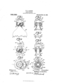
- Figure l is an elevational viewof a practicable embodiment of a form of my invention showing the stopper clamped in its bottle closing position.
- Fig. 2 is a central section of the parts shown in Fig. 1, this section being taken on a central plane through Fig. 1 substantially parallel to the plane of the paper.
- Fig. 3 is an underside view of the clamping member of the stopper.
- Fig. l is a View .showing the bottle in the position illustrated in Fig. 1, and showing the stopper as having been rotated about ninety degrees and raised to its extreme height, the dotted line position of the stopper in this view showingthe position it will assume when it is desired to have the mouth of the bottle open.
- F ig. 5 is a view looking down upon the bottle, as shown .in
- Fig. 4 is a view illustrating the stopper and bottle in the same relative positions they occupy in Fig. 4i, this view being a section taken at about the plane of line 66 of Fig. 4; the bottle and stopper in this instance are shown rotated through about an angle of ninety degrees from the position illustrated in Fig. t; and Fig. 7 is a horizontal section taken on a plane at about the line 'Z7 of Fig. 4, look ing down. This latter View is somewhat in the nature of a diagram for explaining certain of the stopper movements.
- the bottle is designated in a general way by 10.
- This bottle has at its mouth a thickened portion 11.
- the underside faces of such thickened portion constitute a pair of inclined planes 12, 12, for the engagement of the inturned ends 13 of the clamping member or bail 14:, which bail carries the stopper 15.
- On each side of the bottle at the thickened portion there is provided an upwardly directed channel 16 in which the ends 13 of the clamping device will move after the same have run down the inclined planes 1212 when the stopper is being unclamped. This will permit the stopper to be raised from the seat in the mouth of the bottle, which seat in the present instance is illustrated as carrying a sealing gasket 17.
- the channels 16 run only art way to the upper portion of themouth of the bottle and at the upper portions these both extend laterally in the same direction, so that the ends 13 and the entire stopper will when these members are traversing the channels move laterally of the bottle. After the stopper has moved to a position illustrated by the full lines in Fig.
- iit may then be turned upon the ends 13 as pivots into a position illustrated by the dotted lines '18, in such Fig. 4, and also in the position illustrated in Fig. 5, in which position the portion 19 of the stopper will engage the portion 11 of the bottle mouth. It will be noticed that the distance between the lower face of the portion 19 of the stopper and the points 13 is not sufficient to permit the stopper to passover the corner 20' of the thickened portion.
- Fig. 7 where it will be seen that the surface 22 at the bottom of the channel illustrated at the 1 upper portion of such view as this approaches the end of the lateral portion of the channel approaches somewhat more nearly toward the center than does the beginning of such lateral portion. And it will also be noticed that the bottom face 23 of the channel illustrated at the lower side of said view is moved outwardly from the center of the bottle an equal amount. To permit this and still give sufficient material at the end of said channel a mass of material, 230, is built up at this point.
- the dotted line positions 2 1 and 25 show the points 13 in the position illustrated in Figs. at and 6 where the limbs of the bail are in a vertical position and are at the extreme lateral ends of the channels.
- the positions 26 and 27 illustrate the points 13 in the lower portion of the channels l6 and just about ready to run up the inclines 12, 12, for the purpose of clamping the stopper in position.
- the clamping movement will be effected by turning the clamping member in the direction of the arrows 28, 29, and given about a quarter of a turn to the dotted line positions 30, 31, the l lines 32, 33 illustrate the path of movement 1 of the side limbs of the bail from the positions 26, 27 to the positions 30, 31. It will be seen that these paths of movement conform and approach rather closely to the outer surface or contour of the portion 11 of the bottle.
- the members could not be moved in the reverse l direction because the limb 14:, seen in the dotted line position 27, could not if it moved in a direction reversely of the arrow 29 pass the built up mass 23 of material.
- the limb 14 of the dotted line position 26 moves from such position to the position 30 it passes a similar portion of the bottle neck functionally; but the portion is not extended into the path of movement of the limb 14.
- the stopper portion 15 will be made of some suitable material, perhaps porcelain, and will be provided with a stem 3% which may pass loosely through an opening 35 in the clamping member and be held from disengagement therewith by some suitable means, as for instance a wire 36 which may be in the form of a ring, engaging a washer 37 is desired.
- the upper side portions of the clamping member extend well above the top of the bottle to the reduced diameter of the stopper, this being of considerable height vertically, substantially as shown, furnishes the finger space for effectively seizing the clamping member for turning the same forward or back while bringing'the curved cor- 11ers of the clamping member into the proper positions on the thumb and finger of the user, which is a matter of much importance, in order to render the device quick and convenient in operation.
- Fig. 5 the line 38 is drawn through the center of the bottle mouth and the line 39 is drawn through the center of the stopper, illustrating the transverse lateral movement which is given to the stopper by means of the clamp ends 13 traversing the faces 22 and 23 at the bottom of the transverse portions of the channels.
- clamp member is made sufliciently rigid it will be impossible in a structure where the parts are properly proportioned to remove the stopper from the bottle by manipulating the same.
- the fastening 36 may be removed and the stopper removed from the bail after which the bail may be removed from the bottle. This, of course, is an inversion of the mode of assembling the parts.
Landscapes
- Engineering & Computer Science (AREA)
- Mechanical Engineering (AREA)
- Closures For Containers (AREA)
Description
W. E. GASTON. BOTTLE STOPPER. APPLIOATION FILED MAY 24, 1909.
Patented NOV. 23, 1909.
ANDREW. a. Gnmm ea. mo-Lmlgnnmiins. msummor n c WILLIAM E. GASTON, OF WATERBURY, CONNECTICUT.
BOTTLE-STOPPER.
Specification of Letters Patent.
Patented Nov. 23, 1909.
Application filed May 24, 1909. Serial No. 497,880.
To all whom it may concern.
Be it kno-wntha't I, VILLIAM E. GASTON, a citizen of the United States, residing in l/Vaterbury, in the county of New Haven and State of Connecticut, have invented certain new and useful Improvements in Bottle-Stoppers, of which the following is a specification.
This invention relates to bottle stoppers and has for an object to provide an improved bottle and a stopper wherein the stopper will directly engage a portion ofthe bottle when it is clamped in its closingposition and will turn upon pivots and sockets formed in the bottle when it is moved away from the bottle mouth, the structure being such that the stopper can not become accidentally disengaged from the bottle.
My present improvement has for one of its objects to so organize and construct the operative portions of the device as to secure a highly effective mode of operation while providing the hook retaining recesses of a curved formation, both as to the outer edges and also as to the form of the bottom of the same; and also in this connection construct and arrange the bearing points of the clamp member, not only to conform to this construction of the recesses or channels themselves, but to have the other working faces while under the clamping action disposed substantially radial to the aXis of rotation whereby the frictional engagement between the said hooks and the inclined bearings on the bottle will have a proper and normal action.
In thedrawings accompanying and forming a part of th s specification, Figure l is an elevational viewof a practicable embodiment of a form of my invention showing the stopper clamped in its bottle closing position. Fig. 2 is a central section of the parts shown in Fig. 1, this section being taken on a central plane through Fig. 1 substantially parallel to the plane of the paper. Fig. 3 is an underside view of the clamping member of the stopper. Fig. l is a View .showing the bottle in the position illustrated in Fig. 1, and showing the stopper as having been rotated about ninety degrees and raised to its extreme height, the dotted line position of the stopper in this view showingthe position it will assume when it is desired to have the mouth of the bottle open. F ig. 5 is a view looking down upon the bottle, as shown .in
Fig. 4;, with the stopper in the position indicated by the dotted line. Fig. 6 is a view illustrating the stopper and bottle in the same relative positions they occupy in Fig. 4i, this view being a section taken at about the plane of line 66 of Fig. 4; the bottle and stopper in this instance are shown rotated through about an angle of ninety degrees from the position illustrated in Fig. t; and Fig. 7 is a horizontal section taken on a plane at about the line 'Z7 of Fig. 4, look ing down. This latter View is somewhat in the nature of a diagram for explaining certain of the stopper movements.
In the drawings the bottle is designated in a general way by 10. This bottle has at its mouth a thickened portion 11. The underside faces of such thickened portion constitute a pair of inclined planes 12, 12, for the engagement of the inturned ends 13 of the clamping member or bail 14:, which bail carries the stopper 15. On each side of the bottle at the thickened portion there is provided an upwardly directed channel 16 in which the ends 13 of the clamping device will move after the same have run down the inclined planes 1212 when the stopper is being unclamped. This will permit the stopper to be raised from the seat in the mouth of the bottle, which seat in the present instance is illustrated as carrying a sealing gasket 17. The channels 16 run only art way to the upper portion of themouth of the bottle and at the upper portions these both extend laterally in the same direction, so that the ends 13 and the entire stopper will when these members are traversing the channels move laterally of the bottle. After the stopper has moved to a position illustrated by the full lines in Fig.
iit may then be turned upon the ends 13 as pivots into a position illustrated by the dotted lines '18, in such Fig. 4, and also in the position illustrated in Fig. 5, in which position the portion 19 of the stopper will engage the portion 11 of the bottle mouth. It will be noticed that the distance between the lower face of the portion 19 of the stopper and the points 13 is not sufficient to permit the stopper to passover the corner 20' of the thickened portion. In practice it has been found desirable to have a seat en: gaging portion 21 on the stopper, which in the present illustration will engage the gasket 17 and also to have the portion 19 extend downwardly past such seat engaging portion so that not only will this portion 19 act as a pivot or positioning member for the stopper when the clamping portion 15 is being turned in clamping and unclamping, but will also shorten the normal distance be tween the face 21 and the points 13 in so far as the bottle neck engaging function is concerned when the bottle is in its open position.
It has been found necessary to thicken or build up the material of the portion 11 of the bottle neck at the ends of the laterally directed portions of the channels 16 so that the points 13 where these move away from the diametrically opposite sides of the bottle laterally will have suflicient material to prevent them from being moved or sprung out of their channels. It is also desirable to have the limbs of the bail or clamping member 14 as close together as possible to add rigidity to the structure. If the bottle were built up on both sides at the ends of the lateral portions of the channel the limbs would have to be a sufficient distance apartto permit one or the other of these to pass the built-up portion in the rotation of the said clamping member.
Reference may here be made to Fig. 7, where it will be seen that the surface 22 at the bottom of the channel illustrated at the 1 upper portion of such view as this approaches the end of the lateral portion of the channel approaches somewhat more nearly toward the center than does the beginning of such lateral portion. And it will also be noticed that the bottom face 23 of the channel illustrated at the lower side of said view is moved outwardly from the center of the bottle an equal amount. To permit this and still give sufficient material at the end of said channel a mass of material, 230, is built up at this point. The dotted line positions 2 1 and 25 show the points 13 in the position illustrated in Figs. at and 6 where the limbs of the bail are in a vertical position and are at the extreme lateral ends of the channels.
The positions 26 and 27 illustrate the points 13 in the lower portion of the channels l6 and just about ready to run up the inclines 12, 12, for the purpose of clamping the stopper in position. The clamping movement will be effected by turning the clamping member in the direction of the arrows 28, 29, and given about a quarter of a turn to the dotted line positions 30, 31, the l lines 32, 33 illustrate the path of movement 1 of the side limbs of the bail from the positions 26, 27 to the positions 30, 31. It will be seen that these paths of movement conform and approach rather closely to the outer surface or contour of the portion 11 of the bottle. It will also be seen that the members could not be moved in the reverse l direction because the limb 14:, seen in the dotted line position 27, could not if it moved in a direction reversely of the arrow 29 pass the built up mass 23 of material. Where the limb 14 of the dotted line position 26 moves from such position to the position 30 it passes a similar portion of the bottle neck functionally; but the portion is not extended into the path of movement of the limb 14. It will, therefore, be clear how the building up of said portion operates to secure the proper amount of interlock at all times be tween the engaging members and does this in a manner which serves to strengthen the glass by thickening the same, notwithstanding the points of the clamping device when swung over are in a line which is of a relatively considerable distance from the central line of the neck of the bottle.
By tapering the inwardly turned bearing points 13, when the clamp is turned with these points bearing under the inclined bearing faces 12 on the glass a radial disposition of the sides of said bearing points or faces causes them to turn normally and properly in contact under heavy pressure upon the glass incline and when the clamp is, being so formed, retracted and elevated until its narrowed and rounded points come into the lateral part of the curved recesses 16 and said bearing points conform with the formation of the glass down about said recesses, when the clamp is swung into its horizontal position for filling or emptying the bottle, and when lying horizontally is brought up until the upper side of said clamp member is within a short distance of the top of the bottle, which has a result not heretofore practically obtained. By means of this peculiar organization and construction, whereby the conformation is obtained between the pointed and curved bearing ends I am able to secure the restricted dimensions demanded for commercial purposes, and the quick, simple, and effective operation required in practice and at the same time secure these advantages in a bottle in which the top is recessed for receiving the packing ring and in which the points of the bearing ends of the clamp extend inwardly underneath the packing ring when this is in place.
The stopper portion 15 will be made of some suitable material, perhaps porcelain, and will be provided with a stem 3% which may pass loosely through an opening 35 in the clamping member and be held from disengagement therewith by some suitable means, as for instance a wire 36 which may be in the form of a ring, engaging a washer 37 is desired. The upper side portions of the clamping member extend well above the top of the bottle to the reduced diameter of the stopper, this being of considerable height vertically, substantially as shown, furnishes the finger space for effectively seizing the clamping member for turning the same forward or back while bringing'the curved cor- 11ers of the clamping member into the proper positions on the thumb and finger of the user, which is a matter of much importance, in order to render the device quick and convenient in operation.
In Fig. 5 the line 38 is drawn through the center of the bottle mouth and the line 39 is drawn through the center of the stopper, illustrating the transverse lateral movement which is given to the stopper by means of the clamp ends 13 traversing the faces 22 and 23 at the bottom of the transverse portions of the channels.
If the clamp member is made sufliciently rigid it will be impossible in a structure where the parts are properly proportioned to remove the stopper from the bottle by manipulating the same.
\Vhen it is desired to remove the device the fastening 36 may be removed and the stopper removed from the bail after which the bail may be removed from the bottle. This, of course, is an inversion of the mode of assembling the parts.
Having thus described my invention, I claim:
1. The combination of'a bottle having at its month an enlarged portion provided at its lower face with a pair of inclined planes, at stopper, a bail carrying the stopper and provided with inturned ends for engaging said planes for clamping the stopper to the mouth of the bottle, said enlarged portion being provided at each side with channels extending upwardly from said inclined planes, said channels at the upper portions adjacent the bottle mouth being extended laterally both in the same direction.
2. The combination of a bottle having at its mouth a thickened port-ion provided at its lower face with a pair of inclined planes, at stopper, a bail carrying the stopper and provided with engaging ends for said planes for clamping the stopper to the mouth of the bottle, said thickened portion being provided at each side with channels extending upwardly from said inclined planes, each of said channels at its upper portion being extended laterally, both said extensions being toward the same side, one of said lateral extensions approaching at its farther end more nearly toward the longitudinal axis of the bottle than at its other end, and the other of said channels being directed away from the said axis at its farther end.
3. The combination of a stopper, a bail carrying the stopper and provided with a pair of inwardly directed ends, a bottle provided at its mouth with faces for the. engageg ment of such ends and at each side with channels extending from said faces toward the mouth of the bottle and also laterally,
both toward the same side, and a mass of material disposed at the end of each of said lateral portions of the channels.
4. The combination with a bottle having faces directed away from the mouth thereof and disposed on inclined planes, and channels extending upwardly on opposite sides of the bottle from the beginning of the said inclined planes and extending laterally in the same direction, of a stopper, a member carrying the stopper and embodying a pair of side limbs and engaging devices for the said inclined faces, the relative proportion and location of the parts being such that the stopper can engage the side of the bottle between the mouth and said faces when the engaging devices are in the said lateral extensions of the channels.
5. The combination with a bottle having a pair of faces upon opposite sides directed away from the mouth opening of the bottle and disposed on inclined planes, and a channel extending upwardly at the lowest point of the inclined plane on each side, said channels both extending laterally in the same direction, of a stopper for the bottle, a bail carrying a stopper and embodying a pair of side limbs bent inwardly for engag- Lng said inclined faces and for traversing said channels, the relative proportions and locations of the parts being such that the said limbs will hold the stopper against the side of the bottle adjacent to its mouth when the said inturned ends are in the said lateral portions of the channels.
6. The combination with a bottle having a pair of fiat faces directed away from the mouth of the bottle and each disposed on an inclined plane, and a pair of channels having rounded edges and extending up wardly on the respectively opposite sides of the bottle from the beginning of the said inclined planes and both extending laterally in the same direction, of a stopper for the bottle, a bail carrying the stopper and embodying a pair of side limbs and engaging devices having fiat faces for the inclined faces and tapered ends for traversing the channels, the proportions of the bottle, the stopper and the said limbs being such that these will prevent the disengagement of the parts when the bottle is open.
7. The combination with a bottle having a recess at its mouth and having faces directed away from the mouth thereof and disposed on inclined planes, and channels extending upwardly on opposite sides of the bottle from the beginning of the said inclined planes and extending laterally in the same direction, of a gasket in said recess, a stopper having a seat face for engaging the asket and a portion for extending into the bottle mouth, a bail carrying the stopper and embodying a pair of side limbs and engaging devices for the said inclined faces,
sions of the channels.
8. The combination with a bottle having near its mouth a thickened portion provided with faces directed away from the mouth and disposed on inclined planes, and channels extending upwardly on opposite sides of the bottle from the beginning of the said 1 inclined planes and extending laterally in the same direction, of a stopper having a portion for extending into the bottle mouth, a bail carrying the stopper and embodying a pair of side limbs and engaging devices for the said inclined faces, the relative proportion and location of the parts being such that the said extending portion of the stopper can engage and be held upon the said thickened portion of the bottle when the engaging devices are in the said lateral extensions of the channels.
WILLIAM E. GASTON. Witnesses:
AUGUSTUS LYON, EDWARD L. SEERY.
Priority Applications (1)
| Application Number | Priority Date | Filing Date | Title |
|---|---|---|---|
| US49788009A US940926A (en) | 1909-05-24 | 1909-05-24 | Bottle-stopper. |
Applications Claiming Priority (1)
| Application Number | Priority Date | Filing Date | Title |
|---|---|---|---|
| US49788009A US940926A (en) | 1909-05-24 | 1909-05-24 | Bottle-stopper. |
Publications (1)
| Publication Number | Publication Date |
|---|---|
| US940926A true US940926A (en) | 1909-11-23 |
Family
ID=3009345
Family Applications (1)
| Application Number | Title | Priority Date | Filing Date |
|---|---|---|---|
| US49788009A Expired - Lifetime US940926A (en) | 1909-05-24 | 1909-05-24 | Bottle-stopper. |
Country Status (1)
| Country | Link |
|---|---|
| US (1) | US940926A (en) |
-
1909
- 1909-05-24 US US49788009A patent/US940926A/en not_active Expired - Lifetime
Similar Documents
| Publication | Publication Date | Title |
|---|---|---|
| US728981A (en) | Closure for bottles or similar receptacles. | |
| US978585A (en) | Can-top fastener and opener. | |
| US632575A (en) | Bottle-closure. | |
| US1324869A (en) | wolfermann | |
| US835366A (en) | Bottle-stopper. | |
| US1072987A (en) | Bottle. | |
| US731792A (en) | Jar-closure. | |
| US759976A (en) | Oiler or oil-can. | |
| US895907A (en) | Jar-closure. | |
| US2793786A (en) | Closure | |
| US778004A (en) | Jar or glass closure. | |
| US1300896A (en) | Jar-closure. | |
| US599269A (en) | john m | |
| US873869A (en) | Bottle-closure. | |
| US1101687A (en) | Bottle-closure. | |
| US822567A (en) | Bottle-cap fastener. | |
| US1558044A (en) | Closure for collapsible tubes and other receptacles | |
| US830903A (en) | Bottle-closure. | |
| US802195A (en) | Closing device for bottles. | |
| US1845421A (en) | Cover-all cap | |
| US940581A (en) | Fruit-jar. | |
| US436058A (en) | Bottle-stopper | |
| US640182A (en) | Cover-fastening for fruit-jars or similar vessels. | |
| US1133950A (en) | Bottle-closure. | |
| US749063A (en) | Bottle-stopper |